PMA, don't let SYN08 twist your tail. If you are bandwidth limited, then testing for max slew rate is made more challenging, but you get the same benefits of high slew rate.
Many decades ago, I specified that a trans-amp that I designed into the Symmetry xover had a slew rate of 100V/us, but it rise-time limited so it was difficult to measure.
REAL ENGINEERS know the difference between rise-time limiting and slew-rate limiting and don't mix them up.
Many decades ago, I specified that a trans-amp that I designed into the Symmetry xover had a slew rate of 100V/us, but it rise-time limited so it was difficult to measure.
REAL ENGINEERS know the difference between rise-time limiting and slew-rate limiting and don't mix them up.

john curl said:PMA, don't let SYN08 twist your tail.
Thank you John, you are doing a great job in stirring things. This comes exactly when we finally arrived to some common platform and understanding. And at the point of greatly improving this design by suggesting some alternative compensation, that would not kill the OLG to save the phase.
If you need some extra understanding of SR, rise times, noise, NFB, OLG and phase margins, etc... don't by shy, just ask, and I (and I'm sure others as well) will be happy to help you for free.
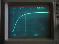
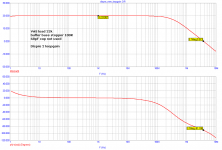
It is not 50V/us. You have to read the highest slope derivative, not the rise time. Hereby 10V step. Rise time is about 150ns, BUT slew rate is at least 4V/30ns, i.e. at least 133V/us. In fact it is 150V/us, as you can see SR above 10Vstep swing. It is 10V/65ns in the previous oscillogram.
Attachments
Here
http://www.diyaudio.com/forums/showthread.php?postid=1710699#post1710699
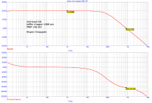
it is at least 10V/40ns, i.e. at least 250V/us. As I do not use the inter-base speed up cap, I declare only 15OV/us.
John is completely right. One cannot mix rise time and slew rate. There is no slew rate for RC lowpass, e.g. Just raise the amplitude and you get whatever SR you want, the response remains V(t) = Vo(1 - exp(t/Tau))
http://www.diyaudio.com/forums/showthread.php?postid=1710699#post1710699
it is at least 10V/40ns, i.e. at least 250V/us. As I do not use the inter-base speed up cap, I declare only 15OV/us.
John is completely right. One cannot mix rise time and slew rate. There is no slew rate for RC lowpass, e.g. Just raise the amplitude and you get whatever SR you want, the response remains V(t) = Vo(1 - exp(t/Tau))
PMA said:Here
http://www.diyaudio.com/forums/showthread.php?postid=1710699#post1710699
it is at least 10V/40ns, i.e. at least 250V/us. As I do not use the inter-base speed up cap, I declare only 15OV/us.
John is completely right. One cannot mix rise time and slew rate. There is no slew rate for RC lowpass, e.g. Just raise the amplitude and you get whatever SR you want, the response remains V(t) = Vo(1 - exp(t/Tau))
Look again on what you posted on your web site http://web.telecom.cz/macura/step_s.gif and compare with what you posted here.
And please, don't pull my leg again by tutoring me differences between SR and rise time. I may legitimately ask you why it took you six months and several hundred posts to finally put together something that finally makes sense. Not to mention several ways to do the same (performance wise) thing at half the price, size and cost.
You should have noticed I wrote measured without input RC filter , this regards the last oscillograms shown.
Input RC filter (1k, 220pF) is a part of every Dispre 2 and completely defines the step response. Then, response can be even longer depending on volume pot setting (10k pot, i.e. up to additional 2.5k).
You should save strong words like 'pulling someones leg'.
Input RC filter (1k, 220pF) is a part of every Dispre 2 and completely defines the step response. Then, response can be even longer depending on volume pot setting (10k pot, i.e. up to additional 2.5k).
You should save strong words like 'pulling someones leg'.
PMA said:
Regarding slew rate, please see measured step response with no RC input filter.
I was asked for slew rate, so I showed responses without RC filter.
syn08 said:
Re: open loop distortions, was it that loading the VAS linearized the whole open loop amp? It makes some sense, I think I've seen this before, but can you confirm?
What about the slew rate?
At these levels you need to look at each distortion component and its phase, i.e. the loading of the output and how it is reflected to the input vs. the input transfer linearity.
scott wurcer said:
At these levels you need to look at each distortion component and its phase, i.e. the loading of the output and how it is reflected to the input vs. the input transfer linearity.
Yep, and this is really something worth looking into, both theoretical and in practice. Between high loads (and therefore not much VAS gain left) and low (but nonlinear) loads there seem to be an optimum... May not be always practical for other reasons (like SR) but nonetheless interesting.
john curl said:You 'engineers' can use some pretty fancy language.
Yep.
A quick update for 'physicians' and 'lifetime IEEE members': there are several Bybee devices available on Audiogon for less than half price! Don't miss them! Example:
http://www.audiogon.com/cgi-bin/cls.pl?cablspkr&1236183203&/Jorma-no.1-w/bybees-3m-pair--w
By reading the description, you would of course notice the amazing non-coloured teflon used by the manufacturer. It is well known fact that the teflon colour deeply impacts the cables sound.
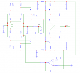
PMA said:Syn08, is there any reason why, instead of those obscure values of C (10000000000000F) and L (1000000000000000000000H) not to use this attached circuit when exploring the loopgain?
IMO it is more accurate and closer to reality.
No, it's ok here. But then you can't always rely on a servo to keep the bias in place. You can't also (for the same bias reasons) to always DC connect the input.
Connecting through very large L and C is only a more generic approach.
OTOH, this way to break the loop applies only in certain cases. Sometimes you need to use the double injection to get realistic results. Do't take it as an attempt to patronize you, but a walk through Dr. Middlebrook GFT theorem fundamentals http://ardem.com/downloads/GFT Article v.3.1.pdf and it's application to simulations http://www.spectrum-soft.com/news/spring97/loopgain.shtm could probably further help.
PMA said:The lower trace is for VAS unloaded, the upper trace is for VAS with 22k load.
PMA would you please tell me how did you measured Output Impedance in MicroCap 9?
Thanks.
Borko.
- Home
- Source & Line
- Analog Line Level
- New DISPRE preamp, successor to previous popular version