Hello all,
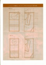
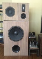
I have reached the end of a 300 hour build of a (mono) Le Cleach type front loaded horn just over 4ft in width with a mouth exit curve of 112 degrees. It has both back and front chambers, and as a prototype, I consider it a relative success - for now.
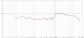
It was modelled in Hornresp around a 6.5in Visaton BG17 (full range with a whizzer) and also a 6.5in Jensen guitar speaker. Why these? Because I had them already, and they are cheap enough to thrash and trash.
At first, the Visaton seemed quite nice, but I suspect the whizzer does not perform very well inside the compression chamber. Somewhat congested, and a bit shrill. It lacks bass, and although lively, it is quite tiring on the ear. The Jensen has much better bass, mids seem nice enough, but lacks clarity in the treble. Both drivers benefit from the use of EQ, and although I love to sit and listen and sing and dance in front of this massive horn, I feel that there is a much greater potential for musical joy as yet untapped.
There does not seem all that much to choose from out there for 6 to 6.5in full range drivers. However, I have read about the 6in MarkAudio Alpair 10M Gen 3. Its physical spec suggests that it would easily fit without having to modify the existing enclosure. My question is, would this driver be suitable for a front loaded horn? And, with its long throw design, would it give a decent amount of bass without an excessive use of EQ?
For what it is worth, I am a practicing artist working with vision and sound, and although technically accomplished, I am NOT an audiophile. My taste in music is, shall we say, eclectic. So long as it engages my emotions, I will listen to anything. As for builders passion, it is horns for me - magical and beautiful.
I would truly appreciate some help with this.
Kindness tapestryofsound


