Toroidal Transformer replacement

Hi all,

I would like to replace a toroidal transformer with Pri 230v / Sec 17.5v - 0 - 17.5v and 8.5 V - 8.5V (5wires). I haven't found anything similar with the 0v center tap.
So i was thinking about to use this one:
30W / 30VA R-Core Transformer PRI 115V/230V 50/60Hz SEC 9V+ 9V / 18V + 18V | eBay

My theory is i need to connect always wire 1 from each color together to have the 0v and the second wire for each voltage as the positive.
But because both sides of the coil have the same color, i will never know which one i use as 0v and which one as positive... do you think this will matter?

Thanks,
Thomas

Help with Gemini Preamp EQ

Hi All,

I made three way speakers, then tri-amp system.
As preamplifier I'm using Gemini PA-7000. Changed transformer, capacitors, BA4558 replaced by NE5532. Found 20% difference in channels output. Temporary 8 pin B20K potentiometer (broken in central loudness dent) replaced by B33K. Still 5-10% difference. Checked first NE on main board and difference was 2-4%(Vcc-14.7/Vcc+15.2). On the second NE5532 placed on Equalizer Board found x1, x10 difference in +/- inputs on left and right channel. Output difference was 15%. With small movement of treble or mid potentiometer the situation become better. Unfortunately there is no direct switch to bypass EQ.
Could You please help me with advise How to bypass EQ.
Thanks in advance
Rauf

Attachments

  • Gemini 7000.png
    Gemini 7000.png
    318 KB · Views: 156

Testboard LME49830

Hi there,

I have built a test board for the LME49830, exactly according to the datasheet. Only conventional components were used, no SMD.
The board works. The sound is warm and clear.
If anyone can use it, I can upload the layout. I do not want it to develop. It was just for fun, the LME49830 has a friend gave me.

regards Olaf

Attachments

  • LME49830_Proto_Top.jpg
    LME49830_Proto_Top.jpg
    193 KB · Views: 1,512
  • LME49830_01.jpg
    LME49830_01.jpg
    256.3 KB · Views: 1,444
  • PCB_TopView.JPG
    PCB_TopView.JPG
    127.2 KB · Views: 1,450
  • schematic.JPG
    schematic.JPG
    110.8 KB · Views: 1,461

Capacitors

Hello,
I have a power supply tranny and two dual mono PS boards from Electrocompaniete AW50.
I would like to use it on another project. The capacitors are 4pin Roe Elna 10000mf 40V.
Any way I can test them to see if they are still good?
Or should I replace them with other capacitors since they are at least 30 yo? would be very helpful if someone recommend how to hook up normal 2 pin ones in this layout, if it is even possible.

any recommendation would be appreciated.

Attachments

  • IMG_9260.jpg
    IMG_9260.jpg
    399.6 KB · Views: 148
  • IMG_9261.jpg
    IMG_9261.jpg
    650.5 KB · Views: 136
  • IMG_9262.jpg
    IMG_9262.jpg
    688.2 KB · Views: 134

buying parts for tube circuit experiments

Greetings!

So I decided to study tube amps and along with reading I would like to perform some experiments. Could more experienced eye look on my parts list and give some insights on what is missing?
The purpose of this is to learn and gather experience along the way. Any advice and suggestions will be greatly appreciated!

Tubes
6N2P, 6J32P, 6N14P, 6N3C

Capacitors
Polypropylene: 470pF, (1, 2.2, 4.7, 10, 22, 47)nF, (0.1,0.22,0.68)uF 630V
Electrolytics: (10, 22, 33, 47, 100, 220)uF - 450V, (47, 100, 220, 470)uF - 100V


Resistors
Metal film 1W 5%: 100, 470, 1K, 4.7k, 10k, 47k, 100k, 220k, 470k, 1M

Other
1n4148, hlmp-6000 LED

Pioneer PRS-D2000SPL

Hi everyone, I have recently purchased 2 Pioneer PRS-D2000SPL amplifiers, and I'm having issues with both of them. I need to replace the driver IC on them both, but the TND505MD ICs are discontinued and I've found an old thread here saying that the guy replaced a TND505MD with an IR2110S, however a modification was done, and he worded it as connecting " the Ground and Common together on the IR2110" but I can only see a COM pin on the IR2110S, while the TND505MD has a GND pin, so I assume they are similar. However the IR2110S also has an additional pin that is in use, pin 15, and it's labeled Vss, while pin 15 on the TND505MD is simply not connected. Could someone with a little bit more knowledge be able to help me after comparing the TND505MD and the IR2110S datasheets and suggest how to modify it to work like a TND505MD. Thank you for reading.

Pass Labs Aleph P troubleshooting

I recently bought my Pass Aleph P 1.7 back from a friend that I sold it to in 2014 after my position was eliminated. This is a commercial Aleph P, not DIY, with remote and uses the IRF610/9610 FETs. My friend had told me that he was hearing some random noise from the right channel, almost sounding like a dirty pot. This was when listening and not operating the volume control or anything.

When I got it back in January, it has performed flawlessly during this time; no noises, etc. that I detected. Until this weekend, when it appeared that the right channel went out. I took it down on the bench. Examining the internals, nothing appears out of the ordinary. I checked the power supplies and everything seems fine. I do have the service manual pdf.

I then injected a 1khz sine wave into the ch 1 inputs. At the output, the right channel was there, but was 1/3 to 1/2 the amplitude of the left channel. After thinking about it a bit and realizing the attenuator was on the output, I took a look at the amp section outputs for L+ and R+ at the 100R resistors R72 (R) and R42 (L). They looked good and were identical in amplitude. I then took two DMMs and connected the + of each to R42/R72 and the - to the bottom of one of the attenuator resistors in each channel. When operating the volume control, the left channel operated as expected. The right channel however was jumping around in a non-linear fashion at certain points, leading me to believe that one or more of the attenuator relays had gone bad. At this point I think I will replace all 16 of the relays (both channels).

The original relays are Aromat DS2YE-S-DC24V, which appear to be discontinued. I haven't found a datasheet for these, but Panasonic seems to own Aromat now. Any suggested replacements?

If anyone can think of any troubleshooting steps that I may have missed, please let me know. One other thing I may replace are the gain pots, but I haven't identified what they are yet, other than I know they are 2K pots. They seem to be working fine.

Thanks for any thoughts.

Making tube Rp disappear now

I recently came up with an interesting approach to make a tube (triode or pentode) lose it's Rp. (ie, go to very high output impedance) This might seem pointless, but if you want to control an amplifier's output impedance via feedbacks, it can be usefull to remove the effect of the usual varying tube Rp. This could be especially useful for SET type amplifiers where only one tube is operating (and varying it's Rp). Class A P-P amps have some (but not perfect) built in compensation for this, since one tube picks up as the other tube lets go. Class B P-P amps have far less compensation of output Z (before global feedback applied) due to non overlap of tube conduction, and that is responsible for some of the 3rd harmonic distortion they produce.

How this works is to operate g1 in positive territory (exclusively, so only some zero bias triode tubes will be suitable, most pentodes can be configured though, via low screen V, and some conventional triodes might be configurable via low plate V if they can supply enough current), and drive it with a controlled current source drive. (instead of the usual voltage source drive) The positive grid 1 intercepts a near constant small fraction of the cathode current stream (at least until the plate V dips down low enough to approach the region of g1 voltage). Lets call 1/Beta the numerical factor for fraction of plate current captured by the grid1. (so Beta is the current gain for the tube in this mode) The current source drive will automatically adjust the g1 voltage to obtain its requested grid current (and so results in the plate current at Beta times that).

So, looking at a triode, any variation of voltage on the triode's plate will automatically be met with 1/Mu opposite voltage variation on the positive grid 1 in order to satisfy the grid current requested. A pentode will operate similarly in positive g1 current drive, just with less voltage variation on the grid, due to the effective high Mu of a pentode. When the plate voltage does not effect the tube's current, we have high impedance, the intended result.

The driver circuit could be a linearized (high gm, cathode degenerated) pentode stage, maybe differential. Or a triode stage with low Rp and some series resistance to the output tube grid.

With the output stage's Rp gone, external combined V/I global feedbacks can be used to set an output impedance. (or for a low feedback design, only a weak local V feedback would be required, since the stage is already providing controlled current. This would set up a current per output voltage mode instead.)

This all would be useful if one wanted to drive a speaker with "critical damping" impedance, say.

g2 current drive might also work, but I'm not sure how well it will hold a constant Beta, since plate V will be dipping down to that V range easily. Beta would be expected to droop some when amplitude is high.

One could even get tricky, and make the output impedance vary in a specified way with amplitude or frequency to control some speaker in a way to compensate for its characteristics. This could be accomplished by a finite output resistance in the driver stage, maybe frequency affected, or frequency controlled outer impedance control feedbacks.

Just as a note. Using V and I global feedbacks have been used historically to control amplifier output impedance. But they typically require high loop gain in the amplifier to make them effective. This current (pun) approach allows one to accomplish similar effects for low or no feedback designs. More likely appealing to the SET crowd or low feedback group.

Cheap Chinese active X-O

An externally hosted image should be here but it was not working when we last tested it.


"HIFI Electronical 2 Way Crossover PCBA ClassA Power Linkwitz-Riley filter 4-Channel Output Crossover-point 2.2K Hz Free Shipping"

I've bought two of these with X-O points at 80 and 100hz for use with sub-woofers for my single driver MTLT systems.

Having frequencies down to a measured 30hz adds a subtle but valuable fullness to some music.

I used MathAudio's free plug in for FooBar to flatten out the peaks in my systems.

Anyway... Has anybody done testing on these $30 active X-Os?
Does the design look OK? 'Seems so inexpensive... less than passive X-Oers.

Thanks, Mack

A few Items for sale - Pcb's, transistors, capacitors

As I have suddenly a LOT of free time, as everyone else! Im having a clear out. All plus shipping

All not used
Clarity Cap ESA - 10uf 250v £5
Clarity Cap ESA - 6.8uf 250v £4
Clarity Cap ESA - 2.2uf 250v £2.50

F&t 10000uf 63v x2 used to test an amplifier, probably around 10 hours use, both £5

Transistor pulls from working equipment all £3 each

Motorola 2955 x2
Motorola 3055 x2
RCA 16112 x1
RCA 38494 x2
2SA1216 x2
2SC2922 x2

Pcb's not used

Peter Daniels universal PowerSupply Pcb x2 £5 each, details here - https://www.diyaudio.com/forums/audio-sector/149672-universal-power-supply-pcb.html

PFM flea, cd clock pcb £3, details here - Ray's Audio Page

Rectifier Bridge pcb from Peranders audio shop £5 details here - RFB03 Rectifier Bridge

Amp topology question/identification

Hi there. I picked up this amp recently for next to nothing. It's a high power (approx 200W into 8) , single ended input amp. It's sounds OK, but lacking some fidelity in my opinion. I'm wondering what kind of amp uses all the same output devices? In this case MJ15024.
I'm also thinking it might be worth ditching the amplifiers and utilising the chassis and 500VA 2 x 45VAC power supply for another project. If so, any suggestions ? Cheers

Attachments

  • IMG_4931.jpg
    IMG_4931.jpg
    638.6 KB · Views: 181
  • IMG_4930.jpg
    IMG_4930.jpg
    636.7 KB · Views: 187
  • IMG_4932.jpg
    IMG_4932.jpg
    721.3 KB · Views: 170
  • IMG_4933.jpg
    IMG_4933.jpg
    629.3 KB · Views: 174

S/PDIF to I2S wiht CS8416 problem unsync SDOUT at startup

Hi,
I have this system:
bluetooth module TS8970 (SPDIF) -> (SPDIF) CS8416 (I2S) -> (I2S) ADAU1701 (ANA)

The CS8416 is in Hardware mode.

When the audio startup or change trace or skip up/down the trace, seem that CS8416 sdout data is tempranealy unsync about the Master Clock and this cause an “CLIC CLIC” on output about ADAU1701.

I have tried this configuration:
each test was done in both conditions:
[CS8416 (master) and ADAU1701 (slave)]
[CS8416 (slave) and ADAU1701 (master)]

TRY1
Master Clock is Recovered Master Clock
RMCK Pin 24 CS8416 to MCLKi ADAU1701

TRY2
Master Clock is oscillator
Oscillator to Pin 25 CS8416, OMCK
RMCK Pin 24 CS8416 to MCLKi ADAU1701

TRY3
Master Clock is oscillator
Oscillator to Pin 25 CS8416, OMCK and to MCLKi ADAU1701
(RMCK Pin 24 CS8416 not used)

It seems that every time the audio stream is interrupted the PLL must hang up again. I also tried to change “Normal /Higher Phase Detector update rate” but I did not solve the problem.
Any ideas to help me?

High Power Heatsinks (UK)

I've just built an Aleph J Class A amplifier with two heatsinks salvaged from some LED light fittings.

The photo is of my almost finished project.

On offer are two more of these light fittings that gave me these heatsinks.

They are huge and enormously heavy so collection only from B98 UK.

I'll take £20.00 each for them.

Attachments

  • 20200316_135510.jpg
    20200316_135510.jpg
    807.9 KB · Views: 237

FS: Alpha Nirvana, SLB PSU, SRR DC Protection boards

For sale are a set of PCBs for the Alpha Nirvana Class A amp, Smooth Like Butter (SLB) PSU, and a set of SRR DC Protection boards. One of the SSR boards has faston connectors soldered on, it was shipped to me this way as it was the board used for checkout from that production run.


$140 shipped in US.

Attachments

  • IMG_20200419_183815.jpg
    IMG_20200419_183815.jpg
    976.9 KB · Views: 170

Xonar Essence STX ii recording - no info above 22KHz

Asus' web specs say this card will record at multiple sample rates including 96KHz and 192KHz. When used with Adobe Audition under Win10 or Audacity under Xubuntu 16.04, the files are at a higher sample rate, but there is ZERO information above a sharp 22KHz cutoff. It's as if the card itself is operating the analog-digital conversion at a lower rate and/or stripping info. See screenshot or spectral analysis.

Can anyone say they've seen the same (or something different?)

I did not see this behavior with my older M-audio Delta 24/96.

Attachments

  • SharpCutoff.jpg
    SharpCutoff.jpg
    294.4 KB · Views: 131

125asx2 in btl ?

Hi everybody,


i bought a icepower 125asx2 from a friend .

i plan to use it in btl with asymetrical ( mono cinch) input.
i ordered a cable set from ghent, china.
but now , i am not shure how to connect the right input to get the correct btl

output !
can anybody help me, my wife fears the house is burning down, in case of wrong connection !😱


thank you for your help !
jochen ( germany )

Capacitor value suggestions please

I am working on an AMC CVT-2030 which was a low budget hybrid EL34 PP amp that I got for basically nothing. Yes, the one with the output tubes soldered in. I have put in tube sockets and used a holesaw on the heat sinks to make room. I can't find a schematic for this model but there is one for the CVT3030 which is basically the same thing with a preamp. My question is about the value of the coupling cap from the drain of the driver MOSFET to the grid of the EL34. The value in the 2030 is .1\250v film. The 3030 is a 1u\250v electrolytic. I have very limited theory and design skills, is there a formula to calculate optimum values for grid coupling caps?

Jeff Bagby's Continuum Build

I think I must have gotten the (or close to) the last kit Meniscus had because the RS28A-4 tweeter is NLA, seemingly for awhile, as I notice it's been taken off of PE's site as well.

Really strange because, I am not a bookshelf or small monitor type. I bought this kit on impulse, and a bit of novelty due to having heard one pair of LS3/5a's in the later part of the 70's. I had a shop foreman, who was from England, who had carted that pair of speakers with him quite a ways around the world by that point. We (myself, and a few of the other shop guys) all hung out together after work and on weekends. Our stereo speakers were typically louder, party type speakers, so we used to joke with him about his little monitors. I had to admit though, in the small efficiency he lived in at the time, they actually sounded quite good, especially after a few beers. Anyhow, that was the only time I have seen/heard a pair of those and had totally forgotten about them.

I have already built a pair of Jeff Bagby's Fusion-12 design from diysoundgroup, which I am quite fond of, so I have a bit of confidence with his designs. So I start reading about the design goals with the Continuum and I come across a picture of the LS3/5 speakers! That tickled me just enough to instantly click the "add to cart" option! And I need another pair of speakers like a hole in the head.

Still, they're little speakers and I didn't expect much, figuring I'll use them for desktops or something trivial. I made the cabinets out of MDF so not committing to any real money in the finish in the event that they just sound so-so. Well, when I fired these little chunks up, I was so pleasantly surprised by how nice they sounded, that they instantly became pricelessly valuable. An instant, favorite small possession.

Is this the best sounding small speaker I have ever heard? Hard to say. All I can say is that even if it isn't, I don't care. I don't, or will never need a speaker that sounds better than this one in this category for a small, 2.1, music only setup. I have it accompanied by a Dayton 12" Ultimax subwoofer.

sczXHwt.jpg

Naim Nait 5i Bypass issue

Hi everyone,

I'm currently facing an issue with my (beloved) Naim Nait 5i from 2005.
When in Bypass mode I have noises coming up on the speakers.

My setup:
  • Naim Nait 5i amp
  • Audio-GD 3.32 Dac
  • HT Preamp Emotiva UMC-200
  • Computer is connected using optical fibre to the Emotiva, and coaxial to the DAC
  • Synology NAS connected to DAC with USB
When using the Naim 5i as in integrated with the NAS or PC, no issues.
When in A/V mode through the HT pream (optical f and unity gain) I'm picking all noises from the PC, hard disks, mouse movements..

So far I've tried different things:
  • Changed the PC power supply to a gold X-650 Seasonic
  • Plug the Naim 5m away from the PC
  • Add some ferrite cores on the PC and amplifier power supply lines
What worries me is that those noises are there even with A/V inputs unplugged from the amplifier so it all comes through power lines. Unity gain is amplifying all defects from the power lines..

While looking for a solution I realized that I had quite some "Humming" in A/V mode with no inputs plugged. (Ground loop ..?)

And while checking I also noticed a strong odour around the power supply capacitors in the amp. Could they be dead? No bulging on these BHC 10000uF and 4700uF

MANY thanks for any help or insight.. !!

WTB Or Trade

Hi,

Looking for the 6DJ8s that HP used in their equipment.
These are the ECC88 or E88CC, I forget which.

I've got this annoying ARC SP10 pre amp that is very
difficult to find quiet tubes in the phone section and parts
of the preamp section. Hence the need for the extremely quiet types.

If you have some and know they are quiet, please let me know
as I need them. I can trade for the Mazda 6V6 tube or Philips 7581As

Cheers,

Threshold SL10 is this cap backwards?

Hello,
Recently acquired this gorgeous Threshold SL10 but it sounds flat and clinical in comparison to my Pass korg B1. Like very flat.

So I had a peak and someone has been here before me. No surprise on an amp this old. Caps need to get replaced so they were. High quality black gate and Panasonic caps used by the looks of it.
But I noticed one cap in an unusual orientation and dining a simple image comparison shows maybe just maybe one of these 47uf 50V caps is backwards.
Am I loosing my mind?

Context:
Both are driving Hypex ncore Nc400s with Klipsch Forte 3 at the helm.
Turntable is micro seiki DD40 with nagaoka MP-150.

I really thought the Threshold SL10 was going to hand it to the Pass Korg B1 but maybe I’m just super wrong.

Would love your thoughts.
Thanks and stay safe.
Jules

Attachments

  • FA472EC3-BB54-4FAE-B200-949964B40CB0.jpeg
    FA472EC3-BB54-4FAE-B200-949964B40CB0.jpeg
    357.5 KB · Views: 93
  • 8C69418A-B695-400D-BE3F-66B0A716A634.jpeg
    8C69418A-B695-400D-BE3F-66B0A716A634.jpeg
    329 KB · Views: 95
  • 6F6CDB6E-A6B2-4770-8779-1485D6374AB4.jpeg
    6F6CDB6E-A6B2-4770-8779-1485D6374AB4.jpeg
    354 KB · Views: 92
  • F6017449-D340-4603-B4EB-6268553994E6.jpeg
    F6017449-D340-4603-B4EB-6268553994E6.jpeg
    349.9 KB · Views: 85

FS a few of the most fun builds I have done

An externally hosted image should be here but it was not working when we last tested it.

An externally hosted image should be here but it was not working when we last tested it.

An externally hosted image should be here but it was not working when we last tested it.

An externally hosted image should be here but it was not working when we last tested it.

An externally hosted image should be here but it was not working when we last tested it.

An externally hosted image should be here but it was not working when we last tested it.

An externally hosted image should be here but it was not working when we last tested it.

An externally hosted image should be here but it was not working when we last tested it.

An externally hosted image should be here but it was not working when we last tested it.

An externally hosted image should be here but it was not working when we last tested it.


These were some of the most fun builds I have done. The AO35 hammond and the B&H speaker boxes are like a blank canvas every build. The amps can be tweaked a zillion ways and you can see how creative you can be with the cabinets. If you look at the brown one you can see the patch cord reel. How awesome is that. It was of course some dry rotted speaker cable that had to be rewound with Mogami gold. I also had to put metal bottoms on the amps for shielding. These are almost dead silent but easily over driven. The brown one is also sporting a modified Newcomb TR-16. My son has been playing and collecting for 30 years and I have done tons of work on his many amps. He auditions each of these for me and every single time he is just amazed at the performance out of these compact units. No two of these ever sound the same...component, layout, tube brand and array give each amp subtle but noticeable nuances. Like I said...these are like a blank canvas and I thoroughly enjoy these builds. I know what they cost to build and 95% of the tubes are vintage but I really don't know what to ask for them. These are one off's and you will not see any others like these. Hydro dipping was expensive and they generally take about 4 - 6 hours total build time. My sons friends have all tried them out and a retired marine friend of mine played a couple local gigs a few months ago with the stars and stripes unit. I have since been inundated with requests for custom logos and configurations for different applications. Any help on pricing these units would be greatly appreciated. BTW...this site has been an immeasurable support group for tips and tricks. Thanks to all the craftsmen...one of which I am not.

500/1 LP filter does not work

My tale of woe:


About 15 years ago I purchased this 500/1 new. Installed it, worked great. That car got totaled and the amp removed about 8 years ago, and the amp has been in a drawer ever since.

I recently decided to install this amp and the 12w6v3-D4 in another vehicle. Hooked it up, no lights of any kind. Found a recommendation to toggle the signal sense switch 5-10 times. Did that, and yay it powers up. No sound though. I turned the LP filter from 12db to Off, and now it plays, but it sounds funny. Not just full range funny, not really distorted, just...not right.

I take the amp to my local car audio place, they have a repair section. The guy acts like I'm a total idiot, has this smirk on his face. Whatever. I explain that the LP filter won't work, and thus the related dials. (Bass Boost, Q, etc) don't work.

He plugs it in to his bench test setup, and, of course, the damn thing won't power on. I leave it in his tender care, he says repair will run $150-$300 if its totally smoked. Fine.

I pick it up, he charges me $160. Apparently he didn't find any failed components but did find a bunch of bad solder joints on the preamp board, gain dial, etc. I hook it up, and guess what. THE DAMN LP FILTER IS STILL INOP.

The sub now plays full range just fine, sounds good, no distortion, as long as LP filter is set to "Off". My current headunit does not have a filter I can turn on, its a junker. I'm planning on replacing it with one that has dedicated sub outs and a built in filter, so maybe its not worth messing around with the amp anymore, but I would like the damn thing to work fully.

After doing a bunch of searching here I pulled off the back cover and lifted the preamp board and pushed it back down 10 times, based on posts here that usually fixes it. It did make a kinda scratching noise the first few times which smoothed out. I put the cover back on and reinstalled it, no change. LP filter on 12db or 24db causes all output to stop. I also rotated the frequency dial fully about 10 times.

I'm already $160 into this thing, and used ones are running $200-$250 on ebay. I'm fully willing to buy a couple and return them until I get one that works. I'm leery of putting any more money in this unit, especially at a repair shop where they didn't bench test the amp for the concern I brought it in for.


So, does anyone have any advice for fixing this myself? Should I just get the better headunit and forget about repairing the amp, as it does work? If I go that route, is it okay to run the sub full range for a while, or could that cause damage? I don't have the gain very loud at all.

I'm hoping Perry Babin might have some input.

Caps 3 PC system replaced with a Hi Quality DIY Renderer

I have been using a CA caps variant PC based music system for some years. IT has a async USB card and SSD fitted with LPS for 12v and 5v components.
A year ago I returned to vinyl, heavily rebuilding a technics 1200 and building a DCT phono pre. This excercise highlighted the shortfall with my digital system- a tiring sound with a lack of fine detail highlighted in piano and violin pieces.
At the time I was working on my vinyl a friend told me of a company in Switzerland who made digital audio boards for the OEM market and sold some with an evaluation board to the DIY market -a bit like Hypex in their early days.
Two months ago he sent me his DIY board for evaluation
I was hooked at first listen, using 24/96 files from Linn library I heard crystal clear piano violins, A bit gobsmacked this unit was producing the closest Ive heard to dear old analogue from any digital equipment ive had connected to my system.
I bought one and built it.
All the family young and old ears consider this is the best so far.
Ive now built my second unit so both my systems are on the new Renderers - CAPS SB touch etc all redundant.
I have mentioned this on the CA forum but there may be more interest here in the DIY project.
The company - engineered SA - electronic, engineering and consulting
The board, which includes the Mr-Mod module, their NMR board
Cost circa 420 Swiss Francs -total cost to me with carriage and EU duty into the UK was £ 340
IT needs an ethernet network in and outputs SPDIF ( I2S is available)
a power supply at 3.3v 450 ma-750 ma
a mini 75ohm SMG coax plug with RG179 cable between board and case outlet
a case
I run it from Jriver on my NAS a with J remote on an old ipad and ipod.
Ill try and post a photo but Ive had 3 attempts so far and all I get is locked out and have to retype this, so its my last go.
If i fail ask me for any more info on the build if needed.
The final case to match my Benchmarks
zkpYnH7.jpg

The inards, PSU on the RHS REg and NMR board on the left
jDN5UZc.jpg

FS: AES Acoustic Elegance TDH12-4 12" Subwoofers - new

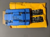
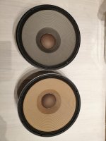
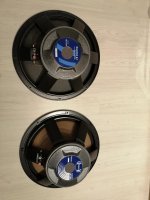
I have a pair of new, used, never hooked up TD12H -4ohm. The "H" version is the best for sub use and for smaller enclosures. Fs = 26

$245 each + shipping. Shipping for one should be around $31 and $51 for both. Free pickup for cash in Denver area.

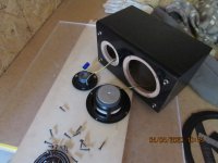
These will come in the original carton with all packaging materials.

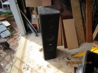
These are great-looking speakers. Would work great as subs or in a 3-way design.

Acoustic Elegance TD12H - Sealed or Vented Box Applications

The TD Series woofers are low distortion, high Xmax, wide bandwidth, bass drivers designed for sealed or vented enclosure applications. The TD12H uses a 4 layer flat wire copper coil. They have the highest BL and also highest mass. This allows them to work in smaller vented enclosures and have better low end extension. They make the best pure subwoofer drivers in the series.

TD12H Highlights:
Lambda Motor with Full Copper Faraday Sleeve (FCFS) (Apollo Option available)
Extremely low and linear inductance
Wide bandwidth and detailed midbass
High Xmax with clean suspension travel
High Efficiency upper/midbass
Designed for sealed or vented box applications
Also ideal for SQ Automotive subwoofers
The TD Series woofers are low distortion, high Xmax, wide bandwidth, bass drivers designed for sealed or vented enclosure applications. They work well in a variety of applications including subwoofers, bass/midbass drivers in 2way or 3way systems, and automotive SQ subwoofer applications. The Lambda Motor means they have very low/linear inductance with response extending cleanly to over 1000hz. The high Xmax allows them to play the lowest notes with accuracy and authority. TD woofers have been used in high end recording monitors, home theater subwoofers, and extremely high end hi-fi systems retailing for upwards of $100,000. When you want the most accurate woofer for sealed box applications, look no further than the TD Series.

So why do you have several versions? What do the different letters, M, S, X, and H mean?

The TD Series woofers come in 4 different varieties allowing for a variety of uses.
The TDM woofers are designed specifically for midbass/midrange use. They have higher efficiency and extremely clean upper end extension, playing cleanly to over 2KHz on axis. The Xmax is lower, 6mm, which is a trade off necessary to achieve the high efficiency.
The TD S, X, and H are all similar and can be used in bass/midbass applications. The core parts (cone, surround, spider, motor, and frame) are the same among all models. The only difference between the models is the wire used to wind the voice coils. All extend cleanly to over 1KHz.
The TDS use a 2 layer round wire copper coil for higher Qts. They are typically the option chosen for sealed box applications and larger vented box applications. They are often used in larger floor standing speakers.
The TDX uses a 4 layer flat wire aluminum coil. The BL is slightly higher and mass is slightly lower. They are typically used in vented enclosures where more efficiency is desired.
The TDH uses a 4 layer flat wire copper coil. They have the highest BL and also highest mass. This allows them to work in smaller vented enclosures and have better low end extension. They make the best pure subwoofer drivers in the series.

TD12H-4ohm
Fs: 26.7Hz
Qms: 3.72
Vas: 160 L
Cms: .4 mm/N
Mms: 88.6 g
Rms: 4 kg/S
Xmax: 14 mm(peak)
Xmech: 18 mm(peak)
Sd: 530 sqcm
Vd: 1.48L (p-p)
Qes: .25
Re: 3.5 ohm
Le: .3 mH
Z: 4 ohm
Bl: 14.4 T/m
Pe: 500W (cont.)
Qts: .23
1WSPL: 92.9 dB
2.83V: 96.46 dB

6aypjfT.jpg

rPDtu8X.jpg

JENc5kt.jpg

kwZVgUk.jpg

lpbSLZV.jpg

QwDHHrI.jpg

cross point suggestion

Hello,
i am looking for suggestions about crossover frequencies for my already good speakers. The drivers are seas excel W26fx001, w15ch001 and t29cf002 tweeter. Now i have them crossed at 180hz and 1980hz all LR 48db/oct and i am very happy. These days and because of the covid-19 virus i thought to play a little with the cross frequencies. The crossover is implemented using SHARC processor (IIR for the filters and FIR for driver EQ and phase correction)so any change is quite easy to implement. What do you suggest that i should try to change? Maybe going the high cross even lower? or the low cross higher? The high cross can't go higher because the 3rd harmonic of the midrange driver so it can only go lower - i think the tweeter can go lower for example at 1500Hz -48db/oct, can't it?

Help with 2 way crossover design

Hello! I am planning on building a speaker but the problem is that I have Little to no knowlage when it comes crossover design / building. I was wondering if I could get some help with picking out parts for a crossover. I was planning on using the Aurum Cantus AC-165 6-1/2" Carbon Fiber/Kevlar Woofer with the Tang Band 25-2234SE 1" tweeter. I would want a pretty bass Heavy sound almost lime the Kef ls50’s but also a good high-end sound like the Bowers & Wilkings 800’s. Could I please get some help?

Sony mds jb940

i have a mds jb940 that i have been working on,i have cured all its issues but one still remains, one of the optical inputs dosent work on the jb940 it has on the back, 1 optical output,
the analogue in and out's 1 coaxial output, 1 coaxial input and two optical inputs, optical input no2 dosent work, cant understand why,
i have service manual and followed it back, on pin 1 it should have 3.3v it has about 0.25v, on that line there are only 2 caps before it is linked
to optical input no1 which works, i have replaced c306, no change, if i remember right the other is surface mount which is possibly beyond my
soldering capabilities, pin 2 is the ground pin which is seperated from pin 1 in circuit by the same caps, that circuit serves all the jacks and ends up at a transistor and switch, then pin 3 looks like a signal pin
that goes through some components to the ic, the other optical jacks go to the same ic.
anyway logic says if the power is not getting to no2 and its getting to no1 then it can either only be 1 of the 2 caps or somehow its not switching on.
there is a button on front panel that switches through all inputs, when it gets to no2 it says c71 no signal.
i know it sounds like a bit of a jumbled up story, but if anybody can give me a pointer it would be appreciated.

Four UCD400

My current amp is:
2xUCD400;
+-50V dual linear PSU;
4x4700mkF per rail;
~500W toroid / quad secondaries;
balanced inputs;
input buffer's gain is reduced to ~18db;
PSU voltage drops to ~+-42V @ 4 Oms with 4V RMS input signal (max volume).

I'm planning to add two more UCD400s into this setup for the bi-amping.

1 there won't be any of the crossovers. Is there anything special I should implement for connecting input signals? Just to do the parallel or to add resistors in series?

2 the extra UCD will be loaded by 2 Oms speaker. Hereafter, I'm planning to add an extra filtering capacitors like 2x3300mkF per rail to the new module. Is this OK? Also, I worry that the transformer won't be powerful enough. Would you recommend to upgrade it to more powerful?

Thanks

Opa2134 Stability Dependent on Supply Voltage?

I have an individual trying to tell me that an Opa2134 will oscillate of used on 12V rails. I can't for the life of me fathom how one could come to such an arbitrary conclusion, and the circuit in question is about as basic as it gets (the first gainstage in a car amp). There are appropriate decoupling capacitors in place as well.

Is there any basis for this? I installed it and scoped the outputs of the opamp and there's no oscillation. I scoped the output of the amp and there's no oscillation. Idle current from my bench supply is super low (80mA from a 12V bench supply), but this individual is convinced that I'm missing the big picture.

Suggestions for next project

Hi guys!

I need your opinions for my next project.

What I have:
A 28 Sq. Meter living room
A class d pioneer LX58 home cinema amp
Morel solus speakers (the main speakers are 3way columns with 2x6.5 mid and midbass)
An 8inch active subwoofer

The problem:
I feel that I need smaller speakers. I really like the morels but most of the time I listen to my music at lower volumes and losing lots of detail, also I am watching movies mostly at night. Of course I've tried all the loudness etc. from the receiver but again, I feel I am losing the details.

What I have in mind:
I don't have enough experience to design my own speakers, so I have to build someone's project.
I feel that a 2way with a 5inch midbass will do the job.
I am looking at troels gravensen designs, especially at seas curv with seas drivers but also I am tempted at many sb acoustics projects but the majority are with sb17 or satori 6inch drivers.
A subwoofer is already installed so bass extension is not a problem.

My question:
Going from a 2x6.5 inch columns setup to a single 5inch/6inch will do the job when it comes to listening to lower volumes?

Do you have any suggestions on 5/6inch projects? I want to keep the budget low, so mostly seas prestige or sb acoustics.

FS: First Watt F6 boards and SMSL M8A dac

SOLDLightly used SMSL M8A DAC, original owner with all parts.SOLD

SOLDFirst Watt F6 boards assembled with matched set of Toshiba 2SK170/2SJ74 parts purchased from "Alweit" on Ebay. SOLD

Both the M8A and F6 boards are in working order.

M8A- 110usd

F6 boards- 110usd

The above prices include shipping in the USA. For sales to other countries, I will need to compute the shipping.
Payment via Paypal gift. I am a long time Ebayer under "drpro" with 100% feedback.

Questions, please PM or call 6154298373
Tnx for looking.
David

Attachments

  • SMSL-1.jpg
    SMSL-1.jpg
    289.4 KB · Views: 173
  • SMSL-2.jpg
    SMSL-2.jpg
    804.9 KB · Views: 166
  • SMSL-3.jpg
    SMSL-3.jpg
    725.3 KB · Views: 166
  • SMSL-4.jpg
    SMSL-4.jpg
    444.2 KB · Views: 162
  • F6-1.jpg
    F6-1.jpg
    321.8 KB · Views: 162
  • F6-22.jpg
    F6-22.jpg
    775 KB · Views: 105
  • F6-33.jpg
    F6-33.jpg
    970.5 KB · Views: 80
  • F6-44.jpg
    F6-44.jpg
    760.6 KB · Views: 75

KEF Daline B110 info needed

Hello fellow enthusiast.
More than 30 years ago I built a Daline transmission line speaker using the following drivers , KEF B110 woofer , KEF T15 mid and a COLES 4001g tweeter. A relative of mine was using it for the last 15 years or so and I have since gotten them back. I find the sound to be dark and not resolute and was thinking of trying some new capacitors in this 3-way crossover. I am not sure if any of these are electrolytics at all and was wondering if any one here can give me some information. The caps all seem to be from the same manufacturer (Erie ?).
Also if anyone can provide me with the construction details of the enclosures including dimensions
Thanks!

Attachments

  • 034.jpg
    034.jpg
    585.4 KB · Views: 470
  • 035.jpg
    035.jpg
    758.2 KB · Views: 457

HDMI->SPDIF extractor + WM8804 = Bad news?

I'm trying to use a Pi + a WM8804 addon board (Hifiberry Digi+ I/O) to do some realtime DSP. TOSLINK in, processing, TOSLINK straight back out again on the same clock. With the clean TOSLINK signal from my desktop motherboard, this works perfectly.

I bought a generic "HDMI->Optical" extractor device, hoping to be able to hook up my contraption to various devices that don't have SPDIF out. The TOSLINK signal from this device works fine when I feed it straight to my DAC, and it works mostly-fine when I feed it to a CM6206-based USB capture device.

But my WM8804 setup hates it. The signal errors out at least once a second, causing constant crackling which obviously isn't acceptable. Cables are known-good; tried multiple HDMI source devices.

I have the chip's "with flags" mode enabled (where various flags are appended to the audio sample itself) and the UNLOCK and/or TRANS_ERR bits are set for the affected samples. This makes me feel fairly safe in assuming the WM8804 itself is losing its grasp on the signal (as opposed to an error between the chip and Pi).

I've been looking through the driver with a fine toothed comb and haven't found anything wrong so far. It's still possible its timing is being set up incorrectly but it looks unlikely at this point (most timing configuration is ignored when the RX is active anyway, according to the datasheet).

The Hifiberry forum's guess was that the jitter/variance from the device was simply too high, perhaps as an inherent result of the audio signal being interleaved with video. However, google shows that the WM8804 has quite a good reputation for being tolerant of jittery signals.

Sadly I don't have an oscilloscope/logic analyser/etc so my ability to investigate much further is limited. Any suggestions would be much appreciated, as would recommendations for particularly tolerant SPDIF rx ICs!

(One obvious thing to do would be to try another extractor device, but aside from being a cheapskate, I'd prefer to be able to receive even questionable signals like this one- it's clearly possible since it works OK with the CM6206 and DAC)

powering two stereo TPA3255 amps using a +/-50Vdc supply

I am thinking about using some cheap TPA3255 amps in an active speaker project. These are readily available from Fleabay (choose carefully!) but come without a power supply. The tricky bit is that a power supply with the right voltage and current capability is not cheap or readily available due to the voltage and current involved.

Being a bit of a hoarder I happen to have some of the ubiquitous dual-output 500W SMPS power supplies lying around that can also be purchased on eBay. I have a pair of these with +/-50V outputs and I am wondering if they could be used to each power a PAIR of the TPA3255 stereo amps. Here is my thinking:

Normally one would need a circa 50Vdc supply for a stereo TPA3255 amp. The PS is single ended, so the inputs are capacitor coupled (reference: the typical application circuit in the datasheet). Could I not connect one of the amps to the +50V supply and PS ground, and connect the other amp between group and the -50V supply? When using the -50V supply, the ground must be connected to the amp's (+) terminal, and the -50V to the (-) terminal.

Assuming this works, I could use the PS with two amps to get 4 channels of amplification on the cheap. As long as I limit the load on any channel to a minimum of 8 Ohms the power demand for two amps should be able to be accommodated by the 500W rated PS. Seems like a very cost effective way to get 4x100W per side.

I just wanted to run this by the forum in case I am setting myself up to let out the magic smoke...

So this showed up on my Facebook page.. Any opinions?

I just had this show up on my facebook page, wondering what you guys think about it?

(No, I'm not affiliated 🙂

MV One – Davis Acoustics

Apparently its using this driver (their own product?) which costs about 785 euros a piece according to Google???

Fullrange speaker Davis Acoustics 20DE8, 8 ohm, 8.7 inch

Seems like a pretty expensive driver to me..?

low cost DSP to improve bass

Optimization of a Subwoofer Line Array with MSO - DSP, Room Correction, and Multi Channel Audio - Audiophile Style
and
Multiple Subwoofers: Optimize Them With Multi-Sub Optimizer Software

These are interesting examples of how low-cost DSP (JRiver on a midrange laptop)plus low-cost / free third party software can massively improve the bass performance of even high-end home cinema installations.

Transformer Polarity.

I think it's about time i learn how to identify transformer leads. I was doing my homework today. It was beginning to make sense until i looked at this thing.
It was a step/ step down/ 1:1 transformer. the 2 black and 2 blue , i believe were the primaries used and combinations for 110 or 220. The two small red leads went to an indicator circuit. That leave one lead for secondary. I know there is none missing. How do i test,and then use it as an isolation transformer?

Attachments

  • hh.jpg
    hh.jpg
    35.8 KB · Views: 178

Steering Wheel Volume & Station change without ASCW-1?

I'm planning to put a double din head unit in my older Porsche. My plan is to buy an aftermarket steering wheel and put 4 momentary switches in the aluminum webbing of the wheel, for volume up/down and radio station change. I will run these through a clock spring with sufficient terminals, which I've found for my car. I don't want any other features. I've seen a few generic head units on ebay whose description say

"Features 2: Support steering wheel control"

Does that mean there will be wires from the head unit that can be used for this?

I would rather not use a control box such as the ASCW-1.

Here is an example of one of the units ebay head unit with steering wheel control

Dipole attempt SB13PFC + LX5 Lineaum tweeter

I've had those LX5 tweeter in my drawer for 25 years I've always like the liveness they can add to the room. I've decided to use them as surround in a dipole arrangement. SB13PFC Woofer back to back sharing the same enclosure. I build the enclosure and measured the response and ended up with a 10db dip at 430hz one octave wide. It is probably mutual cancellation between the two speakers.
Before i undergo cutting the top to separate the chambers, i am looking for other solutions that would not involving woodworking.
I was thinking of running one woofer like a 2.5way, cross low and skip the BSC on the xover.
Are there solutions, any idea or past experience on similar design from you you can share to remove this dip.
Regards


Bipole Lineaum-1.jpg

DSCN1077.JPG

DSCN1076.JPG

Finally building a sub after a decade - Soundsplinter RL-P15

You will see me post this exact thread on a couple other places, because all the forums have shifted around a bit over the last decade and a half and I want as much useful feedback from a diverse crowd as possible. I've been sitting on a single Soundsplinter RL-P15D4 for about a decade now, biding my time until I finally got all the parts for a build (I got the driver, then a calibrated umik1, a db meter, and then finally for my birthday last month I got a Behringer NX3000D) I've moved in between so what was a theater in a 20x20 room morphed to an upstairs 3 wall theater with a 7.1 setup that was 11x21 to about half that because I had to build a room for my mother to move in (so it is about 11x11 now). As I am short on space, I have to make a coffee table style subwoofer with a front/rear firing (I originally was going to do a sonosub). I've already had all the mdf cut for a box that is 11.3cf (320L) with a 8" port that according to WinISD should be 41.15 inches for a 16hz tune. This will fit in the longest size of the box since the external dimensions are 50.5Lx27W.25x20H. My options for the port are evidently sonotube or sewer pipe, the sewer pipe being some super thick stuff that evidently weighs 8lbs per foot. I do have a Creality CR-10 S5 though with which I can print my own (it has a print area of 20"x20"x20").

My main concerns is the ~8 inches headspace enough for airflow (considering I think I have to add around a half inch for the flare. I have seen an alternative to a regular port, which is the Polk power port design which I've seen a couple builds on but they were all before 3d printing was possible (people had to get them turned on a lathe, or use a router to round the disc, etc). So for the same tune, according to the calcs, the port length only has to be 13.215 inches. Assuming the power port works as intended, the nice thing is I can fairly easily adjust the tuning just by increasing the internal port length (which I can do by printing the tube as a threaded two piece pipe).

Any thoughts or should I just stick with a long tube and call it a day? I'm also looking to try and find a second driver, but these things are over a decade old and finding a somewhat unused one will be hard (have to post in the wanted section and see what happens).

Eventually I'll be moving the whole theater down into the basement, but that will be a whole other project (this used to be my grandparents home). It still has a dirt floor basement but for some reason there is a huge concrete walled area in the corner that has 1'3" foot thick walls that are about 4' high and about 12'x6'. If anyone has ideas for that, let me know! The family story is she hired a Polish guy to make a Russian oven and something got lost in translation...the unfortunate thing is that there is enough concrete from that to have put a floor in the whole basement....

Shango

Sparkler Audio - model S508 "esprit" ― MC Phono Stage Amplifier

Sparkler Audio S508 Phono Stage $1,100.00


Specifications (S508v/S508i)
Power Supply: Worldwide, depend on market (IEC 3 pin AC inlet), AC110~120V, AC220~240V (factory assembled)
Input Terminals: Unbalanced RCA pin jack, frame ground terminal.
Input Impedance: 0Ω - total gain is determined by cartridge internal resistance.
Gain: 60..75dB(@1kHz) - adjustable by gain switch.
Type: MC cartridge, CR network RIAA equalizing, NF de-emphasis, current amplifier.
Line Output (S508v - voltage-mode): Unbalanced RCA pin jack, 2.2Vrms
Line Output (S508i - current-mode): Unbalanced RCA pin jack, 5.5mAp-p
Operations: Power switch, Gain switch (high/low)
Size W260×H46×D160mm - B5 size, Weight 1.46g (without power cable)
Materials: Stainless steel, hairline finished. Stainless top panel with clear acrylic.
Accessories: power cable for IEC 3 pin AC inlet, userʹs manual.

flags_1

Small Dayton PS95-8/DS135-8 Build

Hello

As i have ordered a couple of wifi/bluetooth amplifiers (Arylic Up2Stream Amp 2.0), and wanted to build my own first set of speakers for them.
I found the Dayton PS95-8 and DS135-8 to be the right size(and cheap).
So here is the idea i have come up with:
PS95-8 - full range in upper chamber.
DS135-8 as a low(ish) woofer with a DS135-PR passive radiator in the lower chamber.
The lower chamber has these internal dimensions 15cm/15cm/15cm, and the upper chamber is 15cm/15cm/10cm.
I have uploaded a quick rendering of the idea i have.
DX9s1kX

What kind of crossover(if any) would be needed? or would notch filters be enough?
Here is the curve of the 2 speakers.
PotcMIw


Link to the drivers:
Dayton Audio - PS95-8 3-1/2" Point Source Full-Range Driver 8 Ohm
Dayton Audio - DS135-8 5" Designer Series Woofer Speaker 8 Ohm
Dayton Audio - DS135-PR 5" Designer Series Passive Radiator

Kind regards

Plasterboard/dry wall/hollow wall fixings

Hi,

I am doing a little DIY at home, apologies this isnt really audio related!

I have begun to build a cabin bed for my eldest son, which I plan to hang on the wall. The room is literally the length of a single bed, so the bed will be supported on 3 sides.

On the long edge I have a brick wall, and also at one end, and I have some sturdy looking M10 anchor screws, and something like 7 or 8 anchor points along the bed frame length., and foot end, placed every 8 or 10 inches.

So I am then left with the head end of the bed, which is hollow wall.

I'm looking for some suggestions for plasterboard fixings that I can rely on to take their share of the load.


TIA for any help

Attachments

  • 20200402_172012_copy_1382x1843.jpg
    20200402_172012_copy_1382x1843.jpg
    395.6 KB · Views: 165

Identifying transformer leads

Hi all,
I have this Nad 216 THX toroidal transformer but I have no idea how this thing should be wired. It is 120V/230V.

Measurements:

Black-green 0,7ohm
Black-orange 0,7ohm
Green-Orange 0,8ohm

Black-gray 1,0ohm
Black-brown 1,0ohm
Black-red 2,6ohm
Gray-brown 0,5ohm
Gray-red 2,1ohm
Brown-red 2,0ohm

How to connect 230v?

Attachments

  • 451AFEC8-EB64-4405-B31C-8EFB94D03713.jpg
    451AFEC8-EB64-4405-B31C-8EFB94D03713.jpg
    924.1 KB · Views: 127

EL34 Internal shorts

Hi,

I've just entered into the world of DIY tube amps by bringing a old Audio Innovations gen1 800 series back to life.
Only two hours ago, It played music for the first time in years!

The amp was bought second hand for the transformers and some bundled Telsa NOS tubes, still I decided to attempt repair before scraping the original PCBs.

Anyway: The amp shows clear signs of having had at least two instances of all tubes being damaged, prior to me repairing it, now for the third time.
I need advise on how to prevent this from happening again, as PCB and wiring was barley savable this time and next time the amp will definitely be history.

The damaged components indicate the failure mode is as described here: Audio Innovations
quote: "....the EL34's do their special internal short-circuit trick and destroy the cathode resistors (those who have seen their output valves glowing like fluorescent carrots before the sound expired on one or both channels ..........."

Is this an issue particular to Audio Innovations or is it general for EL34 tubes running UL Class A?

Diagram can be found here
Are there any precautions I can take to increase life expectancy of my latest pride amplifier?

Instead of EL34s I'm now using TAD 6L6 WGC-STR tubes. Matched Pairs for both left and right channels. Paraphase phase splitter is using no-name 12AU7 and input stage is Phillips Miniwatt ECC83.
There used to be a large difference (approx 10%) between Cathode resistors for "Push" and "Pull" sides. These are now within 0.5% of 395ohms.

Cathode decoupling caps had busted and are now replaced by 100V types.
Burned out grid stopper resistors on the "UL" grid has been replaced.

Unloaded B+ is 400 volts. I have not been able to measure B+ under load.

Any other measures I should take?

Thanks
Lars

Carver M500 Cap Reversed?

Hello!

I have received a Carver M500 that blows its main AC fuse at power up.

Studying the schematics and looking inside, I notice evidence of previous cap replacement except the solder joints on the two biggest black caps looks original.

Yet, the orientation of one big black cap seems reversed: C509 should have its Neg leg on the Neg trace below--but it doesn't seem so; it appears they both face the same way:

Shared album - Daniel Martinic (Dan) - Google Photos

Mind you, the one in question is oddly turned about 30 deg.. not sure if that's usual.

Should I unsolder this cap and turn it?

REW room Simulation

Hi,

I have a little room (W)2.38m x (L)2.50x (H)2.70m with some acoustic treatment (2" Owens Corning SelectSound® Black Acoustic Board) in the front and back wall, and I am trying to learn to use REW's Room Simulation to get the proper location for my subwoofers (2x).

My questions are:

-. What I am trying to achieve here? The flattest frequency? Or just to lower the modal resonance lines? A peak its better than a null, as it can be equalized?

-. What is a "good" graph? At some models I have peaks of around 20db, and at others it's much flatter but at lower db. Although a total flat graph it's not achievable.

Thanks in advance!

Attachments

  • Capture2.JPG
    Capture2.JPG
    149 KB · Views: 468

Subwoofer project, opinions plesee.

I'm new to this forum so please bear with me with my lack of knowledge, that is why I'm here after all ☺️

I currently have a Bk monolith plus sub which I'm very happy with and want to add another one. This is where my problem begins.

My wife, who has been incredibly tolerant over the years with my hifi & home theatre purchases has finally put her foot down and said NO to another monolith plus. Not because of the expense, to use her words "were not having another big black monstrosity sat in here".

So, we came to a compromise. If i build two subs and make them look like side tables (walnut veneer, the works) she will be happy with that. I'm no stranger to joinery and confident in my skills, also having a brother as a joiner helps!

The subs are for home theatre only.

My initial thought is to use the same driver and plate amp that go into the monolith, but I'm hoping for opinions and suggestions on drivers and amps. I've been comparing drivers, cabinet volumes and port sizes in Winisd to get ideas but I'm no expert!


The maximum cabinet size I can go to is 18.5"W x 19"H x 32"L and would prefer them to be downfiring, vented subs keeping to a similar tuning as the monolith.
Budget around £1000 for the pair.

What do you think?

Altec-Lansing ACS-340/ACS-295 Questions

have come across a pair of ACS-340 Subwoofers and a pair of ACS-295 Satellite speakers. The Woofers have an 8-pin mini-DIN input receptacles and the Satellites have 7-pin mini-DIN plugs. Anyone have a schematic for either the ACS-295 or the ACS-340 systems?

I would like to "marry" the 295's satellites to BOTH '340 subs for a TRUE stereo subwoofer setup. In my humble opinion, bass is not as non-directional as some would have us audiophiles and DIYers believe.

FYI, the ACS-340's specs are as follows:

Satellites: 13W for both channels (I assume this is 6.5W/Ch)
Mono Sub: 27W total (Probably 13W x 2 channels.

I do not have specs for the '295 satellites.

I have to assume that even these systems have rudimentary active crossovers, and if they do, then I maybe I can take advantage of "retro-fitting" them for some reasonably good performance.

I have tried to contact Altec, but they do NOT release schematics.

Anyway, any help would be greatly appreciated.

Thanks and '73,


Steve

Road Kill

I can't seem to help myself
I just couldn't resist stopping to pick these all up Yesterday
I have no idea what I am going to do with all of them but the small boxes will soon be speakers for the 11YO Grand-daughter.
I hate building boxes because my woodwork sucks and the speakers I was building for the femme was vetoed by her mother because they were too big, these little ones might just pass muster tho
Your average big box cheap Chinese speaker system but the Teac subwoofer seems to be working
Fortuitously the little 4" woofers I like to play with are a prefect fit in the woofer hole, all I need now is to find a suitable tweeter, I really don't like those $2- Mylar ones at all

Attachments

  • IMG_1338.JPG
    IMG_1338.JPG
    132.5 KB · Views: 362
  • IMG_1339.JPG
    IMG_1339.JPG
    136.3 KB · Views: 361
  • IMG_1340.JPG
    IMG_1340.JPG
    150.5 KB · Views: 369
  • IMG_1341.JPG
    IMG_1341.JPG
    117.9 KB · Views: 352
  • IMG_1343.JPG
    IMG_1343.JPG
    138.3 KB · Views: 356
  • IMG_1344.JPG
    IMG_1344.JPG
    120 KB · Views: 167
  • IMG_1345.JPG
    IMG_1345.JPG
    144.9 KB · Views: 141
  • IMG_1346.JPG
    IMG_1346.JPG
    124.1 KB · Views: 129

which FW diy for Zu Omen II

Hi

first time posting here, though I we been lurking for some time now 🙂

Was looking for a FW amp for my Omens for some time now, but living in Europe they are relatively rare - and pretty expensive, even 2nd hand (especially J2). Economy being what it is i decided to go DIY way and try to build one but I am unsure which one - F6, F5 or perhaps even Aleph J. From what I read it seems that F5/F6 have more authority over bass (which I fell Omens need); though on the other hand there are some that praise M2 for its tubesque qualities - which usually work well with Zu's. Essentially I would be grateful if you have any input and or experience with the said - or similar speakers - and FW amps.

All the best

Gordan

I want to make a pair of 2 ways loudspeakers reusing the drivers from two old identic

Hi out there!

I have two identical 5.1 systems that doesn't work (I think the problem in both are the power supply, but I don't care about that, I'm interesting on reusing the drivers, they are working fine). The pair of 5.1 sets are logitech x-530 models, detailed specs: (Logitech X-530, Continued - 5.1 Surround Sound on the Cheap | Tom's Hardware).

I have the idea of reusing the satellites drivers and the subwoofer of each old system, to build a pair of stereo two ways speakers. I want to build two boxes to accommodate the 10 small drivers for mid/high frequencies, and install the sub to cover the low frequencies. I would buy a pair of two ways passive filters to separate the frequencies (2 ways passive crossovers). I will power the new resultant speakers with a regular 2.0 channels amplifier (38 RMS watts per channel, 4-8 ohms capable).

I have some questions about this project:

1.- how can I wire the 10 small speakers to connect them to the high-pass filter with a total of 4 or 8 ohms resistance?
2.- What point do you recommend for crossing frequencies with these drivers?
3.- Do you miss any aspect in my thoughts about this project?

Many thanks!

"dead" marantz cd 4000

Hello

I have a marantz cd4000 cd player which has been in storage (dry, safe) for several years and was working when went in...now I am wanting to use it, its not responding at all when plugged in - nothing on screen, no response to keypresses, I can hear a slight hum so internal transformers may be active...
I have downloaded schematics and will try to test power distribution - just wondered if anyone had seen anything like this and maybe there's a common cause (e.g. a fuse or weak connector) - also any tips on where you would start looking for the problem would be welcome!

Cheers
John

Some Class A pcbs for sale designed by xrk971/AKSA/JPS64/Jhofland...

Hi, I have some Class A pcbs to sell. Prices are marked at a good discount already, but all offers considered. Shipping is not included. Shipped from Western Canada.

Image 1: Alpha 20 pcb. I have 2 pairs of these with pads and 1 pair without pads. $30 USD / pair.

Image 2: Dual Rail SLB pcb. I have 6 of these. $12 USD / each.

Image 3: ABBB pcb. I have 2 of these. $75 USD / pair.

Image 4: Alpha BB pcb. I have 2 of these. $45 USD / pair.

If interested, please PM me. Also have a look at my other 3 threads posted earlier for some other deals on Tube, Class AB, ClassD pcbs.

Regards,

Myles

Alpha 20 with pads.JPG

Alpha 20.JPG

SLB's.JPG

Alpha Big Boy Buttah.JPG

Alpha Big Boy.JPG

Horn design help me!!

Greetings all!

Im a broke 21 year old college student from Illinois and im usually active on the audio karma forums. I avoid posting here because the site to me is cluttered and confusing, however it seems there are more people on this website and more participation in the threads and just more in depth knowledge in general.


I am planning on getting a CNC mill soon and want to start making flat pack DIY kits for horns to sell to people, and would love to make some two way and three way systems, I just need to know where to start.


Im only 40% through with my degree in mechanical engineering, so my grasp and ability to understand papers and technical mumbo jumbo (which people have showed me and I have read) isn't that great. Its like a can partially grasp what I read on horn design but not fully.

The smartest people are really, the smart people who can explain things in a way easy enough for the common folk to understand it and im hoping one of you are good at this!

What is the best horn geometry? I realize that some horn types are better than others depending on the situation, and wanted to list all the pro's and cons of the different types fo horns.

Ive narrowed it down to 3 designs
can anyone give me a simplified explanation or list of the pro's and con's of
Tractrix horn
Bi-Radial Horn
Conical

any help??
Projects by fanatics, for fanatics
Get answers and advice for everyone wanting to learn the art of audio.
Join the Community
507,680
Members
7,883,980
Messages

Filter

Forum Statistics

Threads
406,019
Messages
7,883,980
Members
507,680
Latest member
McCoy22