SPICE MODEL MJL3281/1302 need to be repaired

844476d1589600880-spice-model-mjl3281-1302-repaired-soice-jpg


The spice models provided by Onsemi , cordell , Improved SPICE Models for MJL3281A and MJL1302A - Section 1 , do not work in time domain. The internal emitter resistors about 0.04 ohms , can see on datasheet Ic/Vbe function is also forgotten . Can someone help these transistors models work?

It works on LT but not on Tina. Any suggestions?

Attachments

  • soice.JPG
    soice.JPG
    158.1 KB · Views: 363

Forte Model 1 and Forte Model 3 Adjust Bias

I've read a few posts here about adjusting the Bias and I'm a bit confused on which resistors are the emitter resistors. I've attached a pic of the board. Can someone point out which is the emitter resistors and which posts I should get the meter readings from when adjusting?

See attached image. Ultimately, an arrow to the component would be helpful 🙂

Also, there is talk about replacing the pot for a 20 turn and this board has one I believe. Can someone send me a link to the correct POT to purchase? I've got a Forte Model 3 and a Forte Model 1 that I'm getting up and running.

thanks for all you do!

Attachments

  • forte3board.png
    forte3board.png
    579.2 KB · Views: 239

Help! TT, One channel not working

So, I spent all day rewiring the R200 tone arm on my Rega planar 2. I soldered the wires from the bottom of the tonearm into a DIN female, and made a new cable with a DIN male connection. Was a pain in the ***, but now the signal is constant. Buuuuuut the right channel still has no signal. Tested both lines with the multimeter and they come out perfect.
Tried swapping the rcas on my amp, amp is fine...

Any idea? It had this problem before, as well as general instability from bad wiring. Signal coming and going, etc...

Advanced issues in audio transformers.

Hi folks,

So far, I've been winding output transformers with one secondary tap only.

Recently, I started experimenting winding multitap OPTs, and now, with a Williamson style transformer secondary layer configuration, this is where trouble begins.

In my recent prototype:

The primary has 3650 turns, 20 layers.
Each secondary layer has 38 layers (38*3), trifiliar. There are 5 layers

So, logically, there should be the following impedances possible:
1. All in parallel - 74k / 8R
2. 76 turns - 18.5k / 8R
3. 112 turns / 8.2k / 8R
4. 152 turns / 4.6k / 8R
5. 190 turns / 2.95k / 8R

But..

When a series connection of secondaries is made, no matter the order, the series resonance of the coil drops by the double (from 70 to 35kHz) and I see no reason why it should, as the secondary is already low impedance. For this drop in Fres, there must be 4 times increase of capacitance or Ls. It's puzzling.

The funny thing is, different series connections don't influence the Fres. Even one series connection, for example 1//2//3 - 4//5 screws it all and makes no difference to "all layers" in series. The slightly satisfying news is, this resonance is quite damped, since there's no peaking with the intended source impedance.

Although it's not everything...
there is a severe dip following at 53kHz, which appears to be a parallel LC resonance, due to the fact the dip increases with source impedance. More unbelievable is the other fact this resonance, if really parallel RLC, is not depending of the main inductance.

Only parallel connection gives the best measurement, with the Fres of 70kHz. It also lacks the severe dip afterwards.

So I'm creating this thread with any hope to discuss this problem with someone who got already familiar with such issues. I see no reason why series connecting secondary layers should bring such a huge, downgrading difference. It would make sense for an interstage transformer, but on an already low Z secondary?

Proposed 3-way design - your recommendations?

Proposed 3-way design - comments/recommendations?

Hey fellow audio DIYers. newbie here. After 3 months of reading speaker reviews, endless pages of Econowave, dipole and horn design threads, I've decided to build my first pair of speakers instead of buying new 2-way bookshelf speakers for my apartment space. I figure for the same price I can do better.

Accordingly, I am hereby humbly accepting any constructive feedback from this forum's esteemed membership on my below overall design choices before I calibrate my table saw. Thank you in advance!

Objectives:
- medium loudness listening levels in a 16'x16' living room space, 8' high ceiling, music only
- desiring very good hi-fi low-upper midrange accuracy, clarity and balance for jazz, classical, R&B
- total audio components cost to be < $350.00
- will install pre-assembled crossover, not a custom-built crossover (because of job, kids and many hobbies time constraint)
- cannot be huge speakers (wife/GF speaker low dislike factor)
Overall design:
- 100-150W max power, passive, 3-way, floorstanding, 2 speakers only, no subwoofer planned
- committed to 12" woofer in bass-reflex cabinet (3.1 cu.ft.) - enclosure separate from midrange CD horn and supertweeter
- leaning towards a 1000Hz/5000Hz 8-ohm crossover and drivers
- going for controlled directivity with a midrange 1" compression driver horn - so far decided on a JBL JRX speaker waveguide clone like the ones used in the Econowave designs (rated good for down to 1000Hz, and with very minimal "colouration" as I understand it), eg., Dayton Audio H6512 6-1/2" x 12" Waveguide 1-3/8"- 18 TPI
- will order drivers and components from Parts Express and/or other recommended suppliers
- maybe prudent to install L-pads for midrange horns and supertweeters?
- construction: 3/4" MDF well braced cabinet w/ thicker front baffle made of MDF and maple or walnut veneer plywood exterior, internal sound dampening material is still TBD
Specific components:
- woofer, midrange 1" compression driver and supertweeter choices - still TBD
Existing audio path:
- mp3s, flacs on laptop/HDD --> Schitt Modi DAC --> 1990's Yamaha 60W/ch receiver--> speakers
- better hi-fi 100W 2-channel integrated SS amp planned for near future
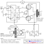
- to add switchover tube amplfier option/experimenting in 5+ years

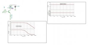
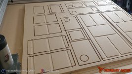
See included 2D frontal scale diagram of speaker design for your reference - this is how I would envision it.

So, what am I forgetting or should be considering? Or recommendations from anyone who has built a similar 3-way? And yes, I have reviewed the "So you want to design your own speaker from scratch!" thread.

Happy listening to all. 🙂

Attachments

  • speaker1.jpeg
    speaker1.jpeg
    52.1 KB · Views: 663

What are my options? Purchased 12AU7/ECC82 to replace 12AU7/6922EH in Bravo Audio v2

*Please let me know if I have posted this in the wrong place*

Hello,

I have created a little problem for myself and I'm wondering what I can do to make use of my mistake.
I'm very new to tube amplifiers, and had a Bravo Audio v2 that I wished to upgrade.

When I looked online, I believed the consensus was that the "12AU7" is also known in Europe under its Mullard–Philips tube designation ECC82, and that these tubes were interchangeable. I also saw that Bravo Audio themselves sold a variant of the V2 with a Golden Lion ECC82, so I assumed I was good to go on buying this type of tube.

I know now, after purchasing a TAD RT005 Tube 12AU7 ECC82 that this is not the case. I found this out by plugging it in and only getting signal from one channel.

I know, I'm probably the biggest idiot for doing this, but I would like to know if there's anything I can do. I have a lot of experience working with circuit boards; is there any modification I can make to the Bravo Audio v2 to make it accept the 12AU7/ECC82 tube?
If not, what's my best course of action? I'm finding it very difficult to find an answer, which is no doubt because of my lack of savvy on this topic, but I would appreciate help. Even just a basic explanation to why and how I messed up would be much appreciated.
I'm finding it hard to find an upgrade amplifier that takes this tube too.

Apologies for the dumb post but I couldn't find anywhere else to ask for help.

Glenn

Small Thor - which XO?

Hi all,

believe or not, it's taken me more than 10 years to finally take those Millenium and Excel speakers off the shelv in my basement and build some Small Thor enclosures for them. I had built original Thor (or rather Hobby Hifi's Evo 04 modification) back in 2003 or so, but when I read about the new enclosures here in the forums I crashed those new boxes and wanted to build new ones. Well, that went quick... 🙂

I know you've all probably moved on to different speakers and are already bored by the Thors, but I'd need some help with the XO. I want to build Jim's improved version, but there are many schematics flying around those threads and I can't figure out which one is the patest and greatest. I managed to find

From https://www.diyaudio.com/forums/multi-way/64799-clarity-seas-thor-kit-post2838726.html:
https://www.diyaudio.com/forums/att...as-thor-kit-reduced-baffle-step-crossover-jpg

From https://www.diyaudio.com/forums/multi-way/64799-clarity-seas-thor-kit-post4541052.html:
https://www.diyaudio.com/forums/att...ty-seas-thor-kit-excel_lr4_crossover_1500-jpg

From https://www.diyaudio.com/forums/multi-way/64799-clarity-seas-thor-kit-post4851083.html:
https://www.diyaudio.com/forums/att...as-thor-index-threads-excel_lr4_crossover.jpg

Is there any chronology to those? What are the differences in terms of sound? Any help would be greatly appreciated!

Thanks, Hauke

Brand New HI-VI Research 8" Kevlar Woofer F8Ba

Just listed 6/7/2020 on eBay for 10 days a new HI-VI Research 8" Kevlar Woofer F8Ba. Please have a look if you are interested.


Cast aluminum basket provides stability
Rigid Kevlar cone for improved clarity
Shielded design can be used near TV's

This handsome woofer features a black Kevlar non-woven fiber cone, rubber surround, and massive cast aluminum frame. Very similar to the standard F8 woofer, this driver provides the same smooth frequency response and very dynamic bass. Specifications: *Power handling: 120 watts RMS/160 watts max *VCdia: 1-1/2" *Impedance: 8 ohms *Re: 6.50 ohms *Fs: 32 Hz *SPL: 89 dB 2.83V/1m *Vas: 1.76 cu. ft. *Qms: 4.59 *Qes: .37 *Qts: .34 *Xmax: 5 mm *Dimensions: A: 8-1/2", B: 7-1/2", C: 4-1/4".

Pioneer Tape Deck CT 1040W - LEFT DECK "B" Motor Stopped Moving :

Hello All :


So today i noticed that the motor is not moving but rest of the mechanism is all good with current. I have no clue what caused that? i was working just fine a few days ago. The other DECK "A" is all fine as well. Some help please. I have attached the service manual with the diagrams for the geniuses to look at guide me with solution please.

Service manual link:

Gofile

PS: I don't think if there are any dried solder connections/traces ... who knows 🙁

Attachments

  • Pioneer CT-1040W.jpg
    Pioneer CT-1040W.jpg
    153.9 KB · Views: 134

Tascam CD-401 MKII Belt

Hello everyone,

I try to repair a Tascam CD-401 MKII which had a broken belt, and it has been removed before I could measure it. I didn't succeed in finding a new one on the Internet, does anyone know if it is the same belt on other Tascam models or the dimensions of the CD-401's one ?
As I have ever build a belt for a turntable from belt sold by meter, I think that I could do the same with this one if I have the proper dimensions (diameter and lenght).

Thanks.

External power supply , safety earth and ground lift

I have a power supply in a separate metal enclosure for use with low voltage audio equipment. the chassis is earthed via a standard 3 pin connector (earth connection). The idea of the project is for this PSU to connect to separate modules (each in their own metal enclosure) via umbilical cords. The PSU has regulated ±20V + earth output(s) (i.e. '3 wire umbilical).
The '0V' line is to be ground lifted:
  • Should the ground lift be in the main PSU or in each individual module?
In respect of 'safety ground':
  • Should the safety ground be connected to each individual module (i.e. a '4 wire connection') from the main PSU?
I would guess there would be no benefit of adding a ground lift in an external module if there's no safety earth connection to the module anyway (?).
Each external module will have it's own internal ± 15V regulator (hence running the main PSU supply to the modules at ± 20V).
  • One of the modules will be a phono preamp which will require an earth connection to the record player as well.
  • The second module is a standard preamp/volume control
  • The third will probably be a DAC.

BTW I had a spare enclosure, ±18V/160VA toroidal, hefty voltage regulator and some nice power connectors (male and female) lying around so I thought I'd make use of them instead of the expense of separate PSU's for each module.
Also only one 'power button' required on the external PSU to power up all modules and one mains connection. 😀

Many thanks!

Soldering 0.5mm pitch footprints.

Had some fun soldering some 0.5mm pitch footprints.
Had some mixed results to start with and found some pads shorted or some not making contact. So on my next pcb I put a line of vias down next to each pin so I could test for shorts and open circuits.

For soldering I was sticking down components with paste flux to hold it in place.
So long as I pressed it well down through the flux it sort of worked OK.

I then watched a youtube video where he cleaned the pads and that worked well. So tried it on one of my PCB's and the soldering worked much better.
I put a little liquid flux on the pads then rubbed it with some kitchen paper towel. The pads then soldered much better.

I found running the soldering iron on the pads back and forth added more solder between pads and pins and looked much better.

Thank goodness for reading glasses and a magnifying glass to check for shorts.

Solstice MLTL from Parts Express

Hi, has anyone built or auditioned the Solstice MLTL kit from Parts Express? I'm really interested in purchasing these as my first DIY speaker project. There's only one review on the site, and my googling hasn't turned up any real hands-on reviews of the finished product. That makes me a little hesitant to pull the trigger, considering the price ($500 per speaker).

Harman Kardon 6600

It looks like it's been since 2011 that anyone posted about this amp. I'm trying to fix mine. Relatively new at this but a background in EE that's not completely useless. The problem I'm trying to address is that one channel cuts in and out, mostly out. Starting with adjustment of bias voltages and some difficulty already. (the measures drift when the speaker switch is off- they seem to be stable if it's on, but the manual says to have it off). Anyone able to advise? Many thanks-

Drop-in replacement for JRC4558

I bought a car dvd recently. Everything is fine except ... the sound quality. For fun, I would like to upgrade the JRC4558 chips (and TDA7338 probably) on the circuit board to some better ones to see if there's any improvement. My question is, is OPA2132U a good drop-in replacement for it? What's the difference between OPA2132U and OPA2132UA?

Also, it seems there are many other chips that I could use, e.g. OPA2228, OPA2134, etc. Which one is better?

Any suggestions are welcome! Thanks!

Doubling crossover’s value

I have a pair of woofer and its crossover networks. I obtained a pair of the same. I’d like to make the dual-woofer system. So, I put a pair of them in a cabinet. Since the driver resistance is low, approx. 3.6 ohms each, I wired them in series connection. The impedance now is about twice of the original, says 7.2 ohms. The original crossover is simply a 2nd order. So thing I have to do is to double the value of an inductor and a capacitor? Is it right? Thank you in advance

Class AB Hexfet Amp Temperature Compensation.

I've been working on an old International Rectifier design from Ap Note AN-948.

Link: http://www.cieri.net/Documenti/Altr...ifier Using Complementary HEXFETs (AN948).pdf

The following semi's were used. Q1, Q2 ; 2N5087. Q4 ; MPSA06. Q3 ; PN2222A. Q5 ; IRF630 Q6 ; IRF9630

The following changes to the schematic: R10; 220 Ohms, added gate stopper to Q6, 220 Ohms.

Source resistors added to Q5 and Q6, 0.22 Ohms 5W.

Q5 and Q6 are on a common heatsink with Q3 held face down between them. Initially Q3 was not touching the heatsink. At 28.3C bias was set to 0.45V across the two source resistors, ~ 102mA. At 56.5C the bias current was 68mA. After I made a little clamp to hold Q3 to the heatsink, the change in bias was worse. At 31.5C bias was 116mA and at 56.8C it shrunk to 47.7mA.

Looking into things further, the Q6 gate to Q5 gate Voltage was 7.83V at 100mA (at 28.8C) and shrunk to 7.13V at 43.2mA and 53.3C. While the heatsink was at 53.3C the bias was adjusted to 100mA and the gate-gate Voltage measured 7.67V.

Note: The above measurements were made without disconnecting the 4 Ohm dummy load so load current could have corrupted the idle current measurements.

Two solutions come to mind. First, insert a stable Voltage in series with the Vbe multiplier like a TL431. It looks like the TL431 needs to be 5.075V and the Vbe multiplier at 2.755V so that the temperature coefficient of the multiplier matches the output MOSFETs.

Second, use a small MOSFET like an IRF510 as a Vgs multiplier. Not sure if this will work because the current in the Q4 is only 5mA.

Has anyone tried these solutions or come up with something else ?

Help! Philips CD80 dead MCU

Help! CD80 gurus. I forgot to plugin the front panel 8-pin data cable when power on the CD80. Then I made a stupid mistake, without powering off, I just hot plugin the data cable. Now I believe the MCU is dead, there is no display, and the turntable motor keeps spinning once power up. I measured the RESET pin (pin 1) of MCU (marked SC409017P P115), it's always 0V, even if I disconnect the front panel data cable and power cable.

Are there anything else I can do to troubleshoot? Does anyone know any low end CD player has the same 68HC05 MCU P115 version I can pull MCU from?

Many thanks!

AYA II Kit / Power Transformer

Checking if there is an interest in buying a AYA II kit (the PCB was fully assembled with all the parts by Audial) + Power Transformer. I purchased this kit directly from Pedja (not thru the GB here on diyaudio)

Apologies for the scrappy enclousure - I put together what I had at the time until I got around buying a proper enclosure - but that never happened :sigh:

This DAC has truly stood the test of time and even to this day has given a good many DACs a run for their money.

Asking USD 525 + shipping. I will cover paypal fees.
IMG_4246.jpeg

IMG_4245.jpeg

IMG_4243.jpeg

IMG_4247.jpeg

Anybody know "Trio" oscilloscopes/tone-generators?

When I was a child I remember not being able to sleep because my farther was testing amps and loudspeakers using a tone generator......

Forty years later I am in a similar situation - the audio hobby is genetically heritable!

Recently, I have dug out the equipment used by my farther including an oscilloscope (Trio CO-1303D) and a tone generator (Trio AG-202A). Knowing my farther he would have bought the "second-best" so maybe this gear is still useful besides the emotional value.

The units works perfectly when powering them on after 30 years of disuse. My idea of recapping the oscilloscope unit was a bit discouraged after opening the unit - everything is wired/soldered so carefully that disassembly will be very complex.....

Advise or opinions anybody?

Cheers,
Nic

Healthy alternatives to foam or rock/glass wool

I'm ready to build some large sound absorption panels for my home (in several rooms) but rather than using 'acoustic foam' or rock/glass wool I would prefer to use something more natural with no VOCs, lung-irritating fibres, etc.


I found an interesting article about healthier alternatives in SOS magazine but the article is already a bit out of date and there was no performance comparison of the options listed: The Green Studio


Does anyone know of a group test comparing some of the greener options such as sheep wool, hemp, coconut fibre, etc? Ideally the material should be fire and insect resistant.


FWIW, I'm planning to build some cloth-covered frames around 1.2m high, 2m long and 10cm deep to house the 4-7cm of insulation plus a modest air gap between the insulation layer and the wall. Something like this:


52774-13873557.jpg

Apparently I’ve built an oscillator.

I have built the amplifier in the attached schematic as it seems to be popular and rather a simple design. I substituted a 12ax7 in place of the 6sl7 in the schematic. Only bad thing is it oscillates like crazy! After the tubes warm up there is a squeal and then it drops into about a 20hz oscillation. If I pull the 12ax7 all is quiet.

I have been through everything more times than I can remember and I’m finding nothing.

Any ideas? Fire away.

Attachments

  • A5DB0692-F9A4-4306-91BD-3E1379F79A75.png
    A5DB0692-F9A4-4306-91BD-3E1379F79A75.png
    52.2 KB · Views: 238

Sansui Sp10

Hello,

At first, I want to apologise for my bad engllish. So ...

I bough't a pair of Sansui bookshelf speaker sp10. They are "made in japan" and I think they where not sell in Us or elsewhere outside Japan. I can't find nothing about them on the internet.
They are bass-reflex with a 12 cm coaxial speaker,
8 Ohms
15 Watt.
So my Questions :
I play them with à pp el34 and find them great , very natural ; but, of course they lack of low mid's (or false bass ).
Do anybody know's about these speaker and have an advice to give me about them ?

I'm thinking to build a floorstand with them but dont know nothing with the caracteristic's of the loudspeaker. and never do such thing.
Is there somebody to give me some Help ?

I thank you too read me.

Best Regard's,
Emmanuel

ESP32 and USB or streaming

I am thinking about a new project with an ESP32 MCU as the main audio source. I have seen projects where it is used to playback internet radio and MP3/WAV files from an SD card.
But would it be possible to use it as an USB soundcard or as a chromecast/spotify/soundcloud player?

I have a hard time finding projects with direct audio streaming that is not just a bluetooth speaker or internet radio.

Kenwood L-A1 often not out of protection

Hi all,
I try to repair this Kenwood L-A1 japanese version 100V/50Hz as it is very often not come out of protection from standby mode.
Hi all,
I try to repair this Kenwood L-A1- a japanese version 100V/50Hz as it is very often can not come out of protection from standby mode.
This amp uses a uCOM to control the whole amp and has also a inrush current limiter circuit with soft start relay etc.
I have tried to replaced all electrolytic caps excerpt two large PS cans but it just sometimes come out of protection if i press the amp on/off several times, most of the case the standby led flickers as long as after you press again the power on knob.
If it comes out of protection i can meassure dc offset just about 18mV from
Speaker both channels and can adjust the idle current 6mV as it describes in the service manual and it runs very good.
All voltages at protection IC 13/uPC1237HA are in manufacturers specs while it comes out of protection and runs well.

But next time in the same day you want to use it it again stays in protection like bollows:
If I press the power on button i hear the power relay clicks, then rush relay clicks, power led flickers, shortly further i hear the the speaker relays clicks or power/rush relays click off i do not know and so it further stays in protection as power led flickers until you must power it off.

For my seeking of reason and my repair purpose i have checked the standby board/circuit there is + 5,6V available for the uCOM as well as + 11 V for the power relay, -12V for the rush relay is also OK, relay driver transistors for power relay, rush relay are OK by DMM diode test.
No components look like burnt, or smoked .
Looking the service manual by protection portion i get 0V or mV at pin 1 of the protection IC uPC1237HA from NEC while the unit in standby or while the led flickers
Now i wants to get the voltage at pin 2 but before I will do it I find on my actual L-A1 kenwood obmits 2 resistors R178 and R179 each 390K ohm it does shows on the service manual so i wonder is it the reason for the protection mode of my amp?
Since I do not understand much from the protection circuit from NEC uPC1237HA so I do not know whether its is Ok with it order not.
Maybe someone of you can explain me that-Thank you in advance!
Here are the links for service manual downloads
KENWOOD LA-1, Service Manual, Repair Schematics
or
Kenwood | Hifi Manuals Free: page 12

Attachments

  • screenshot 1.png
    screenshot 1.png
    335.7 KB · Views: 147
  • screenshot 2.png
    screenshot 2.png
    374.6 KB · Views: 162
  • screenshot 3  standby.png
    screenshot 3 standby.png
    328.2 KB · Views: 134
  • screenshot 4  power and rush relays.png
    screenshot 4 power and rush relays.png
    340.8 KB · Views: 146

Sanway fp14000 experiences.

Hi folks.
I have been increasingly been looking at the Sanway fp14000 amplifier as a next step for my sub set up which will include (4) keystones , 18" tbw100-4 loaded.
The price is attractive and there is a growing base of happy users.
Does anyone here have actual field experience with this unit.
Reports say that this, along with the fp20k are great sub amps, fp10000 not so much.
I recognize 1 user (chrapladm) from the following thread but these guys seem insane in their quest for amps with huge burst power, whereas i need an amp that will be playing several types of edm from tech to rolling dnb with sine like basslines.

I currently have a Crest cc5500 for lows and a crown k1 for the tops and will be starting the subs this winter.
There is a short list on the last page of the thread listing page locations of all tested amplifiers if you don't want to read all 1700+ posts

Measuring Amplifiers - AVS Forum | Home Theater Discussions And Reviews

Any solid advice is appreciated!

On/Off switch using momentary push button

I am in the midst of designing something of a 'universal power supply' for audio power amplifiers in a seperate enclosure.
Most electronics these days seem to incorporate a 'push on, push off' momentary switch design rather than a latching switch.
Any references of how to design this?😕

The switch I am considering using (latching) is a 3 amp/250V coupled to a 300 VA 25-0-25 torroidal. However, would prefer the 'push on, push off' scenario. I guess there should be no problem with the latching switch handling the 1.25 Amps @ 240V nominal current but am a little concerned about surge currents at switch on so using a relay might be the better option - I mention this as possibly a relay would be an integral part of the first question requirements.

Your thoughts would be appreciated.

Diy Strat Pickups Coil Tap Question

Hi there, I'm trying to figure out how to make a more versitile, yet still great sounding strat pickup for John Mayer tones. I really like the sound of underwound JM Big Dipper pickups (are those the same ones on Black1?), but I also love the sound of his '63/'64 sunburst strat (and the prs silver sky which is mostly based on the '63/'64).

Big Dippers (to the best of my knowledge):
- Alnico 5?
- Neck = 5.75k Ohm (7300-7600 turns?)
- Middle = 5.88k Ohm (7450-7700 turns?)
- Bridge = 6.23k Ohm (7900-8300 turns?)

Silver Sky:
- Alnico 5?
- All positions 6.4k (8300 turns?)

'63/'64 (from radioshop and klein):
- Alnico 5
- Neck = 6-6.1k Ohm (7300-7600 turns?)
- Middle = 6-6.2k Ohm (7800-8200 turns?)
- Bridge = 6-6.2k Ohm (7800-8200 turns?)

Suppose you wound pickups with 3 taps (for example a 6.4k pup with taps at 6.23k and at 6.1k), and wired all 3 pickups up to a 3p3t switch. This would essentially allow you to switch between the 3 pickups sets, meaning 3 guitars in one basically. How would this sound, would the unused coil segments (that have no current flowing through them) affect the sound of the pickup? if so how much, would the difference between this set and the 3 normal sets realistically be noticable or not?

Also: I googled dc resistance per turn for a strat and that is what my turn calculations are based off. Am I right or I am off?

Thanks for reading 🙂

Blaupunkt CDP09 CD player

Hi,
First post, so be gentle. I'm trying to repair a Blaupunkt CDP09 car CD player from the early 1990's. I think the Laser head is duff. It's a KSS-164A, and I can't find any info on it or any spares.


However, I have found some KSS-164B's on eBay, and bought some in the hope I can adapt them to work. The main difference appears to be the flexi-pcb has right angle dog-leg connectors on the 164A, whereas the 164B is straight. I'm making up an adapter PCB that hopefully will allow me to use the 164B
What's confusing me is that on the 'new' 164B there is a solder 'blob' on the flexi-pcb shorting the Laser diode out. The same pads exist on the 164A, but there is no 'blob' shorting the pads together. I assume this blob is some kind of antistatic protection for the laser diode, and therefore will need removing before it'll work?


I've diode checked all the connections on the ribbon for both the 164A and 164B - the 6 reader head diodes read Vf=0.765V, and the laser photo diode reads Vf=0.675V in both. There is a difference in the laser diodes though - the LD reads Vf=1.203V in the new 164B (once the solder blob is removed) and Vf=1.521V on the old 164A. Hopefully the increased Vf on the old 164A is indication it's duff.
Cheers
Judwin

BMS 5N160 for a 3 way design.

Hello, I'd like to do a 3 way bookshelf, but I need ideas and your experience. I have this:

BMS 5N160 (91 dB sensitivity) 16 ohms 80-4000Hz
dome tweeter (92 dB sensitivity) 4 ohms 1300-20000Hz
I still haven't decided on the woofer.

What would you do if you had these speakers available?
Would you go for a 3 way bookshelf?
Would you go for a tower? For a MTM?
Would you throw everything and buy a commercial product?

Mainly I want to be able to make a normal LR setup, preferably where I can listen to music and maybe even mix some music, and preferably small in size, a pair of speakers either for the desktop or in a stands behind the desktop.

So far my best idea has been to do a normal 3 way active system, and to make the woofer side firing to maintain a slim cabinet. Since I have 4 of the BMS mid woofers, I've thought on doing them MTM but I'm not sure if this would work...

What are your thoughts?

Thanks!

Audio Setup Advice

Hello, I would like some advice on my proposed setup. It is a nightmare! I have multiple game consoles along with audio and video components. My main purpose for this setup is to enhance and adjust 2 channel sound from legacy components and to split digital signals to analog to adjust if I wanted. It should also allow me to monitor levels with VU meters and have a preview monitor in the loop. I know it is excessive but I want to make sure the connections and path look alright. Thanks in advance.


https://www.dropbox.com/s/gvrse16d3vmvpq4/Audio Path.pdf?dl=1

Musical Fidelity E1 question

Hi folks. I've decided to have a go at fixing a broken E1 to see how it sounds in my office system. I'm new at repairing so am leaning heavily on advice from a friend who has been helping me get started in this hobby.

The amp arrived with blown fuses so the obvious thing was to replace these. Replacements duly blown, I removed and tested the output transistors to find that one on each channel had, indeed, blown as well. So, first culprits identified.

There seems to be next to no information online about these amps and no component lists or schematics, unless anyone here knows to the contrary? I substituted the MF152N main power transistors with TIP3055s and gave it a whirl. Well, it instantly fried R45, located out on the right side of the circuit board.

Unfortunately, the photo I took of the board before starting work has the resistor hidden behind the capacitor! So I now have no way of knowing the value. Of all the photos on line, the least visible resistor is, you've guessed it, R45.

If anyone has an E1 out there and they fancy whipping the top off and send either a picture or the colour bands on R45 that would be brilliant. I've pretty much given up on trying to find a parts list or schematic.

Thanks all.

Crossovers and which Inductor is right?

Hello, I am trying to buy parts for a crossover and have a couple of questions -

L1- calls for 0.259 mH, air core #16, 0.28ohms , I'm assuming that #16 is the guage of the wire? Is 15 AWG okay to use instead?

- next question if it lists the ohms at 0.28 , can I use 0.13 ohms instead?

- - - or does the ohms resistance have to be exact , I figure it shouldn't be more resistance , but can it be less?

thank you,

Mixed Port Sizes - a problem?

I am currently designing a 6.5" ported subwoofer in WINISD. I am still playing around with the box dimensions just a bit, but inner dimensions will be about 23" x 7" x 5". Driver will be mounted on the 23x7 face, and the port must also exit on this face. I am looking to use PVC for port(s) because I already have it, it's easy to work with and elbows are readily available. I will need a 90 degree elbow so it can fire out the front but run the long way in the box to get the length I need.

Problem is... for this design a 2.5" port seems to be ideal with regards to keeping port velocity down. But the only PVC in 2.5" is conduit. Which is fine but the elbows for conduit have a huge sweeping bend and won't fit in my box. I modeled using two 1.5" ports and velocity seemed a bit high (26.5). Using two 2" ports the length is too big for the box (28.5")

So...I was wondering if I could use one 1.5" port and one 2" port?
Has anybody tried this?
How would I tune them?
Is this just asking for trouble?
Any other ideas for solutions?

Thanks

rotel ra-1570 relay clicking quickly to the beat of music

hi everybody,
I've been using a RA-1570 amp for several years and I'm delighted with the way it sounds... however it's been a few months since a relay has been triggered accidentally and switches very quickly to the rithme of the music (on the bass impulses) as soon as I exceed a certain sound level and it doesn't matter what the input (analog or digital) or the output (Speaker A or B) is.
The restitution of the music is not affected, I do not have any cut of the sound signal. In addition this problem is not present at low sound levels or if I do not connect speakers to outputs.
This is rather worrying considering that the disturbance seems to be caused directly by the power signal transmitted to the speakers. 🙁
I would like to point out that the amplifier chassis is properly grounded.
I have tried to locate the relay responsible for this noise but without any real success as it seems to be on a hidden and not directly accessible part after removing the cover. I'm rather resigned because I didn't receive any answer from the SAv of rotel 😡
So I'm going back to your knowledge in the hope of getting some leads to follow in order to locate and eventually solve the problem.
Have you ever encountered this type of problem on a integrated amplifier of this type? What do you advise me to check or investigate?
I thank you in advance for the help you can give me.
Have a nice evening.

Wire for wire-stator ESL

Hi all,

I'm planning a new wire-ESL project and I'm at an impasse trying to find the preferred wire.

I have a stator design and a wire stretching jig setup and spaced for
.054 diameter UL 1429 20AWG single strand wire with .010 irradiated PVC insulation, which I've used on prior builds. However; I am now unable to find that wire unless I'm willing to do a 40,000 foot min-buy (and I'm not).

I came across a source for 20 AWG single strand UL 1061 appliance wire of similar diameter, but I'm unsure about the electrical properties of the semi rigid PVC insulation.

Has anyone tried the UL 1061 wire for ESL's?

Restoring old Krell KSA-50 Ser. 1087.Whats recommende

Bought an older KRELL KSA-50 Serial (1087) which will need cleaning and restoration,
Will need re-cap but what else should I do to get the most out of it for some years?
Best type of fan replacement if needed?

What was changed in the Mk.2 version?
Well used to soldering and building DIY stuff but what are your top recommendations from the vast experience here.
I know they get warm but I like the class A sound. All advice welcome.
Thanks
Liam

Is it possible: single 12ax7 pre and power

Would it work:

A not half bad "amp" which has-
1) single 12ax7 with one triode as pre amp.
2) other triode as a sub 1w class A power amplifier.

Also:
1) I have read that 12ax7 being a pre- amp tube, would have high gain and introduce distortion as a power amp but im ok with a one-trick (but most metal) pony.
2) i posted this here (and not Instr. and Amps forum) because the tube is the whole amp. And that im new here.

Thanks.

12v SLAs for 3116....series or parallel?

I built an outdoor speaker with a 3 channel tpa3116.

The 4" 'sub' bottoms out quite easily. Not sure if the amp is losing control of it or whether it is more down to the enclosure volume, but for this question in the psu section of the forum we shall assume I am looking into the amp side.

It is powered by a single 12v SLA 7ah. If one were to apply another battery to the system to help control the woofer more, would I go for more current or more volts....should I series or parallel the batteries.?

Ofcourse I can easily connect up either way and test by ear, I was just interested in the technical side of it and what the amp and driver would prefer.

Thanks

Shanling CD-T80, Philips CDM-12.10, ticking

My Shanling CD-T80 has started ticking on playback.
Resting finger on puck quietens it.
Should I replace the mechanism?
Do I just replace the spindle motor?

Also, from new the drawer has scraped when opening/closing.
It scrapes on the aluminium plate holding the puck.
The drawer has some vertical play that allows this; the guides do not hold it down, only prevent it from lifting off completely.
Gravity would appear to be what holds it down, perhaps the heavy aluminium drawer front works against this. Anyone come across this and have a fix?

The dealer did fix the drawer noise for a while - I suspect by raising the aluminium plate with some washers I have just found.

Attachments

  • DSCF6143.JPG
    DSCF6143.JPG
    507.6 KB · Views: 150
  • DSCF6144.JPG
    DSCF6144.JPG
    504.3 KB · Views: 147

tower cobbled to ceiling or just buy

new house with no room for our old technics SB-A52 tower speakers so i'm going to need to put my front left/right in the ceiling. I've though of tearing into these towers and using one of the 12" woofers plus the mid and tweeter to make custom units in the ceiling, angling the speakers towards me. Any thoughts on, if done right, i'd get better sound from doing this or should i just go buy some units made for this purpose, such as some with the angled 8" woofer and adjustable tweeter you can get off amazon?

hrl20mxrint9xhvegwlb.jpg


82ac-alt-1_24895504-58d4-4020-84e7-38034745aa68_1024x1024.jpeg

TPA3118 volume control

Hi guys. I'm building a bluetooth speaker and need some advice on volume control. This is a single-speaker amp, so I chose THIS mono TPA3118 based amp. The bluetooth module i'm using is THIS ONE. I'm planning to power them both with a 12v (ish) li-ion pack, or a 12.6v power supply when the unit is plugged in for charging. I'm currently using a 4ohm 5" full-range speaker... but I have a question about that as well that i'll ask later.

When testing last night, the volume seems very high. That is, with my phone connected via bluetooth (or wire) and on its lowest possible volume setting, the volume is higher than i would want my minimum volume to be. Going past half-way on my phone's volume results in the amp being way too loud and beginning to distort.

So i'm thinking i should wire up a potentiometer. I know I need a logarithmic pot, but i don't know how to choose the pot's value. Can someone tell me what value pot would appropriate for this project?

Also, the pot should go between the bluetooth's output and the amp's input, right? Like this:

An externally hosted image should be here but it was not working when we last tested it.


And finally, concerning the speaker: If battery life is a concern, would an 8 ohm speaker be a better choice?

Thank you for your time and advice!

Mandolin box/baffle (re)design

Hi all

After spending way too long looking at speaker designs, reading posts and looking at builds, I'm soon to start building a pair of Jeff Bagby Mandolin's. In the process of reviewing the builds, I came across a handful of low diffraction cabinet designs which I think are much better looking than a big box - namely the SB Ara.

I'm not looking at producing a slanted baffled, as I don't wish to look at the remodelling the XO to account for time delay etc. Afterall, part of the reason I went with a proprietary and proven design was to avoid XO design, however the side/top angles on the baffle I think look great in the Ara. If anyone has modified the front baffle of the Mandolin design in a similar way to the Aras, it'd be great to hear your comments.

I've read Zaphs comments on the importance of reproducing his designs exactly, given his XO's are designed and account for the exact driver placement and baffle. Given this, would it be unwise to modify the Mandolin baffle in such a way as I've suggested?

Thanks very much in advance
Cheers
Brenton

Link to SB Ara - ARA – Sbacoustics
Link to Mandolin Box design on Meniscus website - https://meniscusaudio.com/wp-content/uploads/2018/09/Mandolin-2-Cabinet.pdf

Using scavenged transformer

I have an EI transformer from an old Yamaha AV receiver that I'm hoping to reuse for a project.

My understanding is that at least some Yamaha receivers (this one included) had 2 sets of transformer secondaries for the amplifier section, this one having both +/-28v and +/-40v, and flicking the speaker impedance switch to 6ohm simply switched to using the +/-28v secondaries.

Would it be problematic to use both the +/-28v and +/-40v rails in a project, or is it too hard to know without knowing how the transformer is wound? The reason is that I'm looking to put together a 3 channel (2.1) amp, with the sub running from the higher voltage rails.

Froy Seas MK3 and the studio monitors quest

Hi everyone,


I'm an aspiring audio engineer who's got into DIY speaker building more and more lately. I currently have Neumann KH80DSP that I'd like to replace by DIY speakers.


I'm thinking of building Froy Seas MK3, but I'm having second thoughts after reading that the crossover could be better. Price of the tweeters are another problem too. I already bought 2 Seas W15CY001 second hand.


As other DIYers, I'm always curious for tweaks and alternatives. Filtering and sealed/ported enclosures are my main concerns. So here are those questions :

  1. Can I go sealed ? With a sub, it'd help those 5" cones do the best midrange possible, right ?
  2. What damping should I use ? Do bitumen pads affect the overall volume ? Is sonofil enough (as seen in lautsprechershop.de kit)
  3. Would I get significantly better performance (especially concerning THD and transient response) with DSP filtering compared to passive crossover ? I know this question is too general to be answered. So here's the comparison : DSP combo would be FusionAmp or PWR-ICE and passive combo would be Audiophonics Ncore + Topping D10 + Madisonspeaker Froy MK3 crossover
  4. Do I ask myself too many questions about speakers when I'm in the shower ? 🤔
All the best from France

Any users of these & what is the topology...jung?

After reading Miketts experience of using one rail of this psu at 3v3 for AVCC on an ESS dac I thought I'd try one.

#Aliexpress £12.77 | HIFI DAC power supply Class A dual power supply multiple outputs Dual DC ± 12V ± 15V ± 18V Single 5V 3.3V H151
HIFI DAC power supply Class A dual power supply multiple outputs Dual DC +- 12V +- 15V +- 18V Single 5V 3.3V H151|Amplifier| - AliExpress

Space is at a premium in my streamer build using Ian c
Canada dac parts. I was feeding all 3 dac rails by LT1963 at 3v3 and IV stage was by Studer900 type at+/-15.

I ordered the above psu with 1 x 3v3 and dual 15. It is quite a bit smaller than the Studer900. Used the 3v3 on AVCC of Ian's dual mono ES9038Q2M dac and the dual on the output stage.

Well this brought big improvements to my ears. I don't know which rail brought the biggest change as I did both at the same time. Maybe the AVCC as I understand that it has particular needs and ESS datasheet calls for an opamp based rail here. I had considered trying to cut off the part of the board that carries the single 3v3 rail but it would need to be a very fine cut.

The quality if this board is amongst the best I have seen from Aliexpress /ebay. Nice black mask and gold plate....soldering for THT very clean and shiny, SMD alignment is spot on. Mine came with what appear to be Nichicon input and Panasonic FM output lyrics and I have no reason to doubt at this point. The seller was fast and courteous. No affiliation

The worst thing about the psu is the spacing for the input and output terminals....for the dual rail the 4 holes are too close together to get 2 off 2 contact terminals side by side.

What is the actual topology of this psu....what should I call it? There are no schematics on the vendors pages. I may try to draw one up out of interest but have never done that before.

Any experiences or comments welcome

Attachments

  • 10303213081449211611.jpg
    10303213081449211611.jpg
    309.7 KB · Views: 306

Replacement for softboard/speaker protection relays

hi - i just bought and soldered the speaker protection board from Diyaudio. The relay 653-G5LA-14-CF-DC12 from the BOM is obsolete (I do not know why they do not inform the users before purchase). I have informed the store but they said they are not technical and cannot help.

The suggested replacement part from mouser does not fit the pins. Does anyone know the correct replacement part? I need the 24vdc one.

Could you also inform diyaudio and tell ask them to update the part number to help others?

thank you

Philip

HV USB Oscilloscope

Hi all! I was looking at USB oscilloscopes and I realized I will be working with 450VAC. Some of the USB oscilloscopes advertise ranges from 10V to 40V. Is there a line I could be made aware of? Should I stick with a benchtop for tubes? I was going to use my Xonar STX card to output arbitrary waves, so a complimentary USB oscilloscope would be better IMO. If I'm stuck with benchtop what's good for tubes?

thx Beka D:

Help me to understand the maths for anode choke / IT

I am currently trying to understand much better the maths when using anode chokes or IT...and found some articles and tools about it, but clearly it is not a topic which seems to be as popular than explaining RC coupling...so I trust in the knowledge of this forum to get some more light and knowledge around this topic.

I am considering two use cases:
- Line Stage with OPT-Output (fully differential, LTP, current source, 4p1l or 10y)
- Driver stage of PP: Either Anode Choke or IT (6n6p into el34 currently, later maybe 6n6p/801a into 300b, all LTP with current sink)

What I found so far:

http://www.vt52.com/diy/tips/platechoke.xls

...a nice tool to calculate the frequency behavior for a selected tube/inductance.


My questions popped up yesterday when I read about differential driver stages:
basic-tube-5

I asked myself:

- What of the normal RC-Coupling-Calculation like for instance Calculating RLa with RLa=Ra/Rg are still true when using Anode-Loads (still C-coupled) or directly IT ?

- In case of an Anode Choke: What is the Ra for the purpose of calculation the output restistance of the driver stage ? I understand the formulars for AC where the chokes makes this a very big/infinitive impedance for the AC with raising frequency...but how do I understand RLa when the bridging relationship of 1:10 output/input impedance is met ? Somehow I am guessing that the output impedance of the driver stage will not become infinite ?

- Example: two pairs of El34 need to be driven by a 6n6p which is feed through an 150H Anode choke, but still C-coupled. The El34 got 39k grid resistors each. So, how bad is the situation ?

- What changes in terms of binding the driver to the output stage using an IT ? I guess we do not need a gridresistor anymore, the secondary of the IT becomes the grid choke as well...but how to calculate RLa ?

What I would like to understand much better is: When I would try to do the same calcs as Mr. Turner explained on LTP-Drivers (RC-coupled) but for Anode-Choke/IT: How do I calculate this so I can evaluate which options for tubes, bias-points, IT-step up or step-Down ratios I should consider.

Last example: I read from Kevin Carter and others that they like the sound of their line preamps much better with IT/OPT which have a step-down-ratio of 4:1...ok, I guess that may be empirical observations, but obviously it raises the question why this is needed when you work already with tubes like the 4p1l (rp around 1500 ohms) and driving a tube-input stage of 100k input-resistance...?...plus destroying the gain of your line-amp ? Not such an obvious choice...

SMSL SA-98E & TDA7498E - opinions/mods

Hi guys,

Anyone have experience with this amp?
Its my 3 amp from smsl and i have to say it does sound very good , such a small device and huge power, this version is suplied with 35V and 5A power supply which is different to the older one 35V 5.7A

Also this version of amp has smaller caps.

Do you know maybe if there is any room for improvements to get even better sound from it?


Thank you!

1.jpg

2.jpg

3.jpg

4.jpg

5.jpg

6.jpg

7.jpg

8.jpg

Do I really need a relay for on-off switch?

Hi. I am planning a build where I have 2 SMPS (a 350w 48v meanwell and a 60w 5v XPpower). I will be using the 48v for my amp and 5v for raspberry pi and also to power my USB DAC separately (so not powered through RPI USB port). I have 2 questions.

1. I was planning on having an on-off switch between the mains and the PSUs so that both PSUs and the devices connected to them all get power at once. My IEC connector is fused and has a switch but would prefer one on the front.
For me simpler is better as I am still just learning. I have a (very) old Sharp tuner that I might gut out and use the chassis for my amp. This old tuner has a nice push button of-off switch that is connected straight to the mains (with a fuse in between). The switch has lasted about 50 years so obviously had not been stressed in its application. There is writing on the side which says 250VAC/3A/20A. I am in Australia and we have 240V mains. Unsure whether that means it is rated to 3A or 20A. My do PSU's are like 7.3amp and 8A but unlikely to be using that in my application. Regardless though, I imagine that I would be putting more that 3A through it and most certainly a lot more than the tuner was using. I have also read about the issue on inrush current but am still unclear if this is only an issue if the switch is between the PSU and the amp. Is the safest and simplest thing to do here to have the switch just switch a relay with a 240V coil and say 30A rating. Something like the link below? Would this mean the switch is only going have a small current going through it?

HF105F-4/240A1HSTF | Hongfa Europe GMBH SPNO Non-Latching Relay Flange Mount, 240V ac Coil, 30 A Non-Latching Relay | RS Components

2. I was also planning on having a selector switch to swap between the analog inputs at the back of the chassis and the analog inputs coming intot he amp from the the DAC. I was planning on using a signal relay for this and possible powering the relay off the 12v aux supply off my 3e TPA3255 board. If doing this then it would make sense to me that the selector switch would also be connected to a relay which would switch off the power to the 5v psu powering the RPI and DAC. I am guessing that I would need to separate relays. Would it work to have the selector switch hooked up to 2 relays - one 12v signal relay and one 12v relay rated for 250VAC with 30A rating? Something like

https://au.element14.com/panasonic-...lay-signal-dpdt-30vdc-1a/dp/1200949?st=tq2 12

and

https://au.element14.com/multicomp/mc25154/relay-spst-no-250vac-24vdc-30a/dp/1688657

Together they draw around 100mA according to the datasheets. The 12v output on the 3e board is rated to 200mA so should be ok I guess. If this would work ok, would a SPST be ok with wires going to the coils of the relays connected together? The way I see it is they are both only going to the relays so no mixing of signal/power? Or would it be safer to use a DPDT selector switch.

Thanks,
Mark

Need help fo 100w+per channel stereo chip amp

Hi,

I'm a newbie when it comes the real power amplification. I've build simple speakers and headphones amps in the past but it's my first attempt to build an amp.

I'm looking for a stereo amp that can produce 100w per channel at 4 ohms. Based on my search on this site, I will need a parallel configuration to achieve these results. Based on what I saw, it seems that there are no kits available so I'll have to get the parts by myself. I would need help to figure all the parts I'll need to get this little amp working.

You help is really appreciated.

Max

R/2R DACs

Dear Members,

do we have a topic dedicated to R/2R DACs ? I tried to search but not much hits at all, to investigate a bit the - probably - appreciable sonic differences between these kind of DACs and conventional ones.

I also know there might be subtle differences among them too, ones built with discrete resistors and ones with ICs.

That's all I know and not sure if I'm correct at all with the last sentence, but I'd like to know more about them and especially hear opinions of those who have already worked with some. :shy:

For me it seems a bit like the DSD/PCM debate: which sounds better despite fundamental technological differences.
Projects by fanatics, for fanatics
Get answers and advice for everyone wanting to learn the art of audio.
Join the Community
507,743
Members
7,886,335
Messages

Filter

Forum Statistics

Threads
406,147
Messages
7,886,335
Members
507,743
Latest member
Fitodiod