Had some fun soldering some 0.5mm pitch footprints.
Had some mixed results to start with and found some pads shorted or some not making contact. So on my next pcb I put a line of vias down next to each pin so I could test for shorts and open circuits.
For soldering I was sticking down components with paste flux to hold it in place.
So long as I pressed it well down through the flux it sort of worked OK.
I then watched a youtube video where he cleaned the pads and that worked well. So tried it on one of my PCB's and the soldering worked much better.
I put a little liquid flux on the pads then rubbed it with some kitchen paper towel. The pads then soldered much better.
I found running the soldering iron on the pads back and forth added more solder between pads and pins and looked much better.
Thank goodness for reading glasses and a magnifying glass to check for shorts.
I had an incredibly bad experience with .4mm pads on a BGA in a 6 layer PCB. Simple solution, go to a shop that has done it before (in this case China, no one in the US or Europe could promise success).
I'll remember those ideas even if not a super fine pitch layout. Anything that helps get a decent assembly is important.
I'll remember those ideas even if not a super fine pitch layout. Anything that helps get a decent assembly is important.
0.5mm pitch is not a problem, even not at home. I often solder such tiny smd components, but what i use is a hot air station and not a soldering iron. It is possible to use an iron, but this is way more complicated. If you get shorted legs, use some soldering wick to remove them. At this pitch less solder is better.Had some fun soldering some 0.5mm pitch footprints.
Had some mixed results to start with and found some pads shorted or some not making contact. So on my next pcb I put a line of vias down next to each pin so I could test for shorts and open circuits.
For soldering I was sticking down components with paste flux to hold it in place.
So long as I pressed it well down through the flux it sort of worked OK.
I then watched a youtube video where he cleaned the pads and that worked well. So tried it on one of my PCB's and the soldering worked much better.
I put a little liquid flux on the pads then rubbed it with some kitchen paper towel. The pads then soldered much better.
I found running the soldering iron on the pads back and forth added more solder between pads and pins and looked much better.
Thank goodness for reading glasses and a magnifying glass to check for shorts.
If you want perfect results use stencils and solder paste with hot air stations. This is the way this pitches are intended to get soldered.
Solder paste, stencil, converted toaster oven - 100% reliable in my experience.
<=0.5mm is not really suitable for a soldering iron, though some can get away with it, hot-air rework is so much easier. Always use fresh flux and the minimum amount of solder. (And then clean the flux off)
<=0.5mm is not really suitable for a soldering iron, though some can get away with it, hot-air rework is so much easier. Always use fresh flux and the minimum amount of solder. (And then clean the flux off)
I've found that it really helps to pre-heat the board. If it's small enough, you can use one of those Mr. Coffee-style coffee cup warmers. But a real hot-air rework station works better, especially when the part has a thermal pad. I bought a rework station on Amazon; the best $80 I ever spent!
Which one do you recommend? (I dont have access to one ATM, considering purchase).I bought a rework station on Amazon; the best $80 I ever spent!
Do you hold the component down when blowing with the hot air, or does it stick to the board? I had bad experience with a component being blown away, went back to regular soldering iron instead. Pitch 0.5mm with subsequent solder wick is quite easy, but a less laborious/time demanding way of soldering individual components would be handy. I do not want to bake the board since I cannot place 0.5mm components exactly without them moving a bit when baking. I solder one pin, re-adjust the component (TSSOP) under microscope, and solder the remaining pins. Doable but laborious. Or maybe I am doing something wrong...
Thanks a lot.
Thanks a lot.
Do you hold the component down when blowing with the hot air, or does it stick to the board? I had bad experience with a component being blown away, went back to regular soldering iron instead. Pitch 0.5mm with subsequent solder wick is quite easy, but a less laborious/time demanding way of soldering individual components would be handy. I do not want to bake the board since I cannot place 0.5mm components exactly without them moving a bit when baking. I solder one pin, re-adjust the component (TSSOP) under microscope, and solder the remaining pins. Doable but laborious. Or maybe I am doing something wrong...
Thanks a lot.
Your technique is exactly the one I always used. Working under a microsope (Stereo Zoom) makes a world of difference.
This is the one that I have: <https://www.amazon.com/gp/product/B01M4KF3V2/ref=ppx_yo_dt_b_asin_title_o09_s00?ie=UTF8&psc=1>
I try to keep the airflow at a minimum (~7%?). Chip manufacturers will usually have a reflow temperature profile that you should follow. (They're all pretty similar.) I start with a preheat of 150C and let the board sit for 10-15 minutes. Then I turn on the hot-air gun and gradually ramp the temp up and down per the data sheet. I've been able to do 0.5mm-pitch parts with thermal pads with good consistency. But do plan to throw away a few parts as you gain experience! There are plenty of youtube videos.
Also, I've been buying my boards from China with a solder stencil. I think it's an extra $10 at pcbway. You can find solder paste at Digikey, and this really makes any SM job go quickly. 0603's are no longer an issue for me, but I have yet to try 0402's. Placing such small parts with tweezers is a challenge, as my hands are a bit shaky from too much caffeine.
Trying my first steps in smd I acquired a cheap hot air/soldering iron station -Baku BK-702B- from a local shop. I found that it works best to set in rather high temp -400 C which is hardly reaching 200 C on the board- and at the lowest air pressure using a medium 6mm hose. I leave the solder paste of the refrigerator for some time and then it becomes rather liquid and sticky enough to hold the components in place. Don't worry if the paste is not precisely shaped on the pads. Just ensure that it is somewhere about and most important at a minimum quantity.
BSST: It's doable, all details are perfectly visible. I did 0402 capacitors adding SATA slot to a motherboard with a soldering iron under a microscope. But it takes a lot of time for more components.
jlevro: So you are using a combination of the pre-heating platform and hand-held hot-air gun? Do you "visit" all components one by one with the gun?
MagicBus: You are using gun only, no pre-heating platform? You don't use a stencil, just put the cold solder paste manually pad by pad?
Thanks to all.
jlevro: So you are using a combination of the pre-heating platform and hand-held hot-air gun? Do you "visit" all components one by one with the gun?
MagicBus: You are using gun only, no pre-heating platform? You don't use a stencil, just put the cold solder paste manually pad by pad?
Thanks to all.
MagicBus: You are using gun only, no pre-heating platform? You don't use a stencil, just put the cold solder paste manually pad by pad?
Thanks to all.
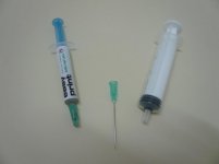
Yes, I only use hot air gun. Pre-heating or not, the board needs to be heated. I do it with the gun circling around the component. I don't use stencil but I leave the paste to reach room temp before I apply it. I made a diy hose that does the job much easier. See attachments, hopefully self explanatory.
Attachments

jlevro: So you are using a combination of the pre-heating platform and hand-held hot-air gun? Do you "visit" all components one by one with the gun?
Pretty much. However, the station comes with 4 different nozzles, so you can cover as much or as little area as you want. I've learned to use larger nozzles so I can heat an area, but it's important to keep the air flow as low as possible. I slowly "wave" the gun over the surface. It's really cool (?) to see the solder melt and the parts pop into alignment. I guess surface tension is real....
")
The few times I've soldered TQFP packages with a normal soldering iron, I found that on a HAL finished board, shorts are much easier to see than missing solder. So I'd rather short a few pins and fix it with solder wick than to miss pins. Hot air with low air flow is indeed much more convenient.
Are You using Flux ? It helps a lot !!
Absolutely! I like Chipquik products, available from Digikey.
- Status
- This old topic is closed. If you want to reopen this topic, contact a moderator using the "Report Post" button.
- Home
- Design & Build
- Equipment & Tools
- Soldering 0.5mm pitch footprints.