PP EL84

Quarantine forces me to resume a long ago forgotten project. Twentyish years ago I bought tubes and transformers for an EL84 PP project. To make things easier (maybe) I ordered one of these 6N4 / 12AX7 + EL84 / 6P14 Push-pull Tube Power Amplifier 10W+10W Stereo Amp PCB 699998773739 | eBay
It's on the way, but I was wondering about the power supply. I have a Hammond 272HX which will give me 600VCT. Worries my B+ will be too high with the 220mfd and 6.8.k on the power supply?

Honey Badger Build... where to start?

I bought the following from the DIY Audio store today.


1 Mezmerize B1 Buffer 1 Universal Power Supply 1 Soft Start & Speaker Turn-On Delay / DC Protector Combo 1 The diyAB "Honey Badger" Class AB Power Amp - 150W/Channel

Not even sure if all these boards can be used together. Should I incorporate them all into one chasis, is the preamp ment to be standalone with it's own chasis power supply?

The more I read up on each, and all of the choices people have when building them, the more confusion arises. This is seems like it's going to get expensive pretty quickly 😉 haha.

I plan to mostly use this amp with 8 ohm speakers, don't think I'll need the full 150 watts RMS per channel. Most likely just some decent 2 way speakers.

Do I really need 8 10ku filter caps and a massive 800va transformer with 45-0-45? Can I even use the universal power supply with this amp?

Are there any common alternatives to the chassis, maybe some asian sourced chassis at a reasonable price?

Thanks in advance for any tips from others who have had and found answers to the same questions.

Regards,

Mike Drz

JL Audio A1800

Looking for advice on this A1800. I had all the power supply FET's blown, most of the gate resistor out of tolerance. It didn't seem to blow the drivers, they test ok (in circuit). I was going to test it without the FET;s in first. So when I applied power 12.9 volts, both my power and protection light are on.

I have no waveform coming out of the 3525, pin 2 has 6.95vdc on it. Pin 16 (5.1v reg) has 7 volts on it.

Maybe the 3525 is bad, since it blew all the FET's, but it didn't blow the drivers, so maybe not.

Attachments

  • JL Audio A11800 .jpg
    JL Audio A11800 .jpg
    1,018.5 KB · Views: 98
  • JL Audio 2.jpg
    JL Audio 2.jpg
    1 MB · Views: 86

Heat Sink question...

Greetings:

I couldn't find a better place to put this (but if there is, let me know), so here it is. I have a copper finned heatsink and am trying to figure about how much heat it can dump. My attempt included sanding smooth the bottom of an 8 ohm power resistor and using some CPU thermal paste to transfer as much of the heat into the heat sink. The attached table (below) shows what temperatures I saw.

The big issue is trying to figure out how much of the wattage generated by the resistor was transferred to the copper, and how much was radiated by the resistor directly to air. Note that a LOT of heat was being transferred to the room. The ambient temperature in the room had bumped up to 30C at the time of this test run (it was 104F outside).

I'm hoping to use the sink for a MoFo, but I'm concerned that it can't quite sink enough. I am also considering using two, and having them brazed together at an angle with a triangular block of copper to give the brazed parts strength, a solid copper bridge to spread the heat, and use it as a base to mount the MOSFET on.

Any thoughts on how much of the 32W going into the resistor are actually going into the copper heat sink? Once that is answered, the C/W should be easy enough to calculate...

Attachments

  • copper80x80x20.PNG
    copper80x80x20.PNG
    12.1 KB · Views: 266

Zenith 3000 Speaker Question

Hi all,

I'll freely admit I'm a new forum member and don't know a tremendous amount of information.

And I'll also admit the thought of what I'm proposing might horrify a few so if that's the case you can ignore my post.

I'm looking to use my father's old Allegro 3000 speakers in my garage without a receiver.

My thought was to attach headphone jacks to each speaker and get a y-connector to attach both speakers to a phone or Echo dot to be able to quickly attach when I'm in there working.

We attached a headphone jack to one speaker and tried it, but the volume was extremely low. I'm guessing that it needs more power to get any decent volume so what I'm trying to do will probably not work?

Thoughts? Maybe the headphone jack wire is to thin and I need to use thicker wire to attach the headphone jack?

Need advice on notch filters or BSC for FE207 simple BR

Dear listers

I have mad several searches and found some hints but not the definitive answer.

I have have built the fostex simple BR cabinets for the FE207E and use them on KR 300bs Tube amps. Even though they are wonderful, they visibly need some correction, a thing I expected. Based on your actual experience with these drivers and cabinets, which kind of filter and what values would you advise for this kind of tube amps?

I am quite a newbie as regards filters.

Best,
JSB

Willing to help a total newbie with assembly tips for Fostex horn kit?

Hi,

My first post and it's a long one. Thanks in advance to any help or advice you can give me.

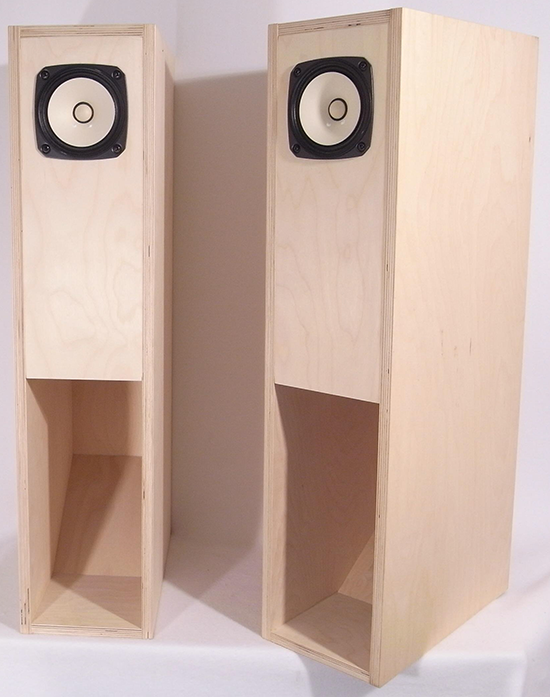
I just purchased this kit (I bought the small Foxtex-branded back-horn bookshelf kit a year ago and it's a ton of fun): Fostex BK-12m Folded Horn Kit - Pair

And of course, I need to build it! I have very basic shop skills (as in, grew up working on cars, sanding things, fixing things around the house) but I currently own no woodworking tools (as in clamps and such) or real woodworking experience, but I have a full suite of hand and power tools. I will buy what I need along the way. Of course, it is complicated with the virus and popping into Home Depot, Woodcraft, etc. isn't what it used to be.

The instructions have you glue it together one piece at a time (and dry fitting, clamping adjoining pieces to get a perfect fit). This makes sense and I plan on following these instructions. I plan on buying and assortment of clamps (instructions suggest a minimum of 2, 36" and 3, 24") and also buy a few of the ratchet strap clamps. As you can see, all of the parts are slotted and they fit together well (so well you need to sand them to loosen up to fit), so this would be a cakewalk for most of you! For me, I want to do it right vs just jumping in and regretting it later.

Suggestions on what clamps and glue I should buy?
Titebond - Glue, 16 -oz

In less detail than below, should I finish before assembly, or assemble first then finish?

*****

OK, where I am adding some complexity:

--I would like to finish the cabinets. Just something very basic. I am liking everything I see about Danish Oil in terms of the looks and ease of applying. In theory I would like to finish before assembling (to get the visible, inside areas of the horn finished), but I am not sure this is practical (having to protect all those joints from getting finish on them...bad for glue) and I would want to sand after I build to remove any slop in the joints.
https://www.homedepot.com/p/Watco-1-pt-Natural-Danish-Oil-265503/203164644

--I was considering doing a ¼" to ½" roundover on all external edges, but I don't have the tools or technique to do this (at least not well), and am planning on passing. I might try to sand off the sharp edges.

--I would like to have the driver secured with T-nuts (would be nice to easily remove to play with the stuffing in the driver chamber), but there is not a lot of room to work with. Don't think traditional T-nuts would work well with this plywood (vs. particle board). If I used these, seems like using epoxy is smart to keep them from spinning and trapping your drivers (no way to get a hand inside there). Thoughts?
Parts Express #8-32 Hurricane Nuts 50 Pcs.

I'll leave it there, as this is already too long of a post and you are too kind if you read it all and answer.

Thanks!

Ken

An externally hosted image should be here but it was not working when we last tested it.

Stray Capacitance

I am trying to figure out the right input resistance to use to roll off high frequencies above 8Khz in a preamp 12ay7 tube. I need the total capacitance, Miller capacitance, same thing right?

Values added for 12ay7:

Ct = (gk=1.3pf + stray) 27mu*(gp=1.3pf + stray)

I found article with a 12ax7 showing that the stray capacitance is 0.7pf.

Would it be close enough to just assume they are the same?
How would I find the stray capacitance if not?
Is there any chart showing all tubes miller capacitance?

TU-8500 Broken Switch

I recently assembled a TU-8500 Preamplifier kit and I enjoyed it quite a bit. Unfortunately one of the push switches was damaged and/or faulty. Once pushed in it won’t release. Does anyone have a part number so I can order a replacement?

For anyone attempting this kit, you might consider using heat shrink tubing to connect the switches to their shaft in Step 1 of the Body Assembly. I believe forcing the vinyl tubing over the switch shaft may have caused the damage. Thanks for you help.

WTB a good 25 mm voice coil dome tweeter?

Hi,

Refurbishing an old Kef tweeter, I'm looking for a 4 ohms textile tweeter 1" tweeter dome ! No screw but adhesive double tape method.
Good power handling needeed. (200 watts)

Any idea of a place to shop please ? I assume the Qtm and the Xmax has to see with the dome/suround/plate assembly.

Voice coil is 4 ohms and exactly 25 mm diameter. 27 mm textile dome, 30 mm with suround shaped from the fabric.
I thought about some brands, as Audax, Morel, but has mostly no idea and where to look for to have some choice... Better to buy a new tweeter with close spec. or better to change the dome to keep the spec of the motor ?


Many thanks,

Help with grado ra-1 clone

Almost finished this grado clone pcb and I need advice how to calculate pot for this amp. I installed gold plated socket for njm4556ad, gold plated output socket, little wima's and elnas plus two ecwfe 2,2uf mkp input caps.

Resistors also have sockets so I can change gain if I need to but pot will be soldered in so I need to pick ideal value to cover multiple gain options (if pot ever have any influence on that). Thanks 🙂


I have chosen 47K at R1 and 22K at R2 and R3 which is about 4dB gain.

US Amps us25a/us50a issues.

Snagged a us amps US25A circa 92-93. Little sucker wont power on. Visual inspection shows nothing out of the ordinary on the power supply side. Inspecting the output side I see two burned resistors that upon measuring are essentially open. These two resistors are in series with all 4 LARGE resistors on the outputs of the TIP35c/TIP36 bipolar transistors.

Any idea what value resistors are the burned ones?

To those who have built Goldwood 18" OB H Frame...

Just got four Goldwood 18's, and am planning my baffles. to those who used the 1858 in the H-frames: Did you follow the design and dimensions in the MJK article or did you use your own? I am looking to build a dual woofer H-frame and am unsure of what dimensions to use. 20"x40"? 16" deep? Did you offset the baffle forward to eliminate the magnet sticking out, or leave it centred?

I was thinking an Hframe like this:
http://www.linkwitzlab.com/proto.htm

FS various Hypex UCD modules and SMPS'

I've got some Hypex amp modules and SMPS modules from a multichannel amp I built years ago for a pair of active speakers. Originally it was 4xUCD180 HXR, 2xUCD400 HXR, 2x SMPS 400/180 and 1x SMPS400/400. However I now have 4 UCD 180 HXR modules and 1 SMPS400-180 module that powers 2 of them, the other SMPS for the other 2 went to a mate who blew an amp power supply. Then there is the UCD 400 HXR and one SMPS400-400 which powers it. There was originally another UCD 400 but I gave it to another mate who's little girl thought putting tiny metal Xmas table decorations in his amp vents was a good idea. So all in all there are now 4xUCD180 HXR, 1xUCD400 HXR, 1x SMPS 400/180 and 1x SMPS400/400.

I am selling the modules all together, although if they don't sell, I may consider selling them individually. I've tried to price them for a quick sale though so are a bit of a bargain. I'll throw the case in as well, it's pretty rough and ready fashion in a Modushop box, it's got XLR and speakon connectors on the back and originally had a powercon for power connection but I have used that for another project somewhere. Just replacing that and doing a small amount of soldering would get you back to having a couple of channels of UCD 180 working pretty quickly, Although you may eventually want a new case for it.

£360 covers 50% of the new module costs.

Shipping free.

Icepower 1200as and NCore NC122MP wiring help.

Hi.
Im building two amps, one with Icepower 1200AS module an the other with Ncore NC122MP for my active speakers.
I saw a power (stand by) switch on Youtube that I like. Are these two amplifiers can be switched on in this way or i need any additional circuit?
In standby mode, the LED is red and green when it is turned on.

YouTube

I would like to use this button:

LB Bistable Aluminium switch with RGB light 250V O16mm Silver - Audiophonics

The Ncore NC122MP will be used in stereo and bridge (BLT) configuration.
From the picture in datasheed I do not fully understand how to connect the source to the amplifier in bridge configuration. I will use XLR input.

I would greatly appreciate your help.

Attachments

  • blt.png
    blt.png
    23.5 KB · Views: 367

FS: 6GK5 Mullard + Hitachi + WH + PCL82 Telefunken (<>) + others

TUp for sale are tubes:

-6pcs SOLD 6GK5 MULLARD (Great Britain mark on it) NOS, I have just run a few test with them
Price: 18 EUR / pcs

-9pcs PCL82 TELEFUNKEN (<>) diamond NOS, some are NIB
Price: 10 EUR / pcs

-2pcs PCL82 VALVO used a few hours (10-20)
Price: 10 EUR /pcs

-12B4A RCA, Sylvania, CBS more then 10pcs NOS
Price: 8 EUR /pcs

-JRC 3A5 tubes pcs
Price: 8 EUR / pcs

Shipping worldwide.

6P6S triode strapped output stage: first pass experiments.

Triode strapped SET output stage: 6P6S and 6P1P-EV

Today I got some time to try an output stage based on some Reflektor 6P6S I bought a few weeks back (before the world stopped turning).

I built a test board, some weeks ago with sockets for each valve model, so it should allow easy comparison between the two valves.

Initial results with the 6P6S are quite encouraging. I have yet to try the 6P1P.

Setting up a self biased stage, fully bypassed cathode resistor, using a Jan Western 4k/5k OPT.

B+ used was 250V and 300V. Anode to G2 connection via 220R resistor.

Rk of 820R, bypassed by 470uF gives Vg of approx -22V, and about 25mA anode current, in quiescent condition.

Using this setup, the output stage gain is in the region of 5.5 V/V. (Open loop)

Working backwards, for 1W into 8R on the secondary (3V RMS) requires about 99V swing on the primary - probably about the maximum clean voltage swing, using a triode on 300V HT. (5k primary wdg)

Using a small transformer to step up voltage into the output stage, since the signal generator is limited to 7V RMS, and observing the input voltage with an oscilloscope, and I require about 16V RMS drive to reach just over 1W output.

Next ideas to try:

0, try an equivalent circuit with 6P1P.

Or...

1, LED cathode bias at 22V, or more perhaps, in order to accommodate a larger input signal.

2, connect G2 to the unused 4k OPT tap, for about 10% distributed loading - expecting more gain and output, how much? Who knows?

3, cathode CCS (more work)

Any ideas other than these?

Which one should I try first?

Any and all input welcome.

Stay safe folks

T-S data for Philips AD 10100/W8

Hi,
I am after the Thiele Small data for a vintage Philips AD 10100 /W8 10 in woofer, I can't find it in the TS database and only know the Fs is around 25 Hz.
I don't have one to test, but can probably get some. I am considering it as a substitute for a box that originally had a vintage Vifa P25WO (Fs 24 Hz Qt 0.28 Vas 180 L). Being active, with a low crossover, getting the response and efficiency to match, is not a major concern.
Thanks
Andy

Onkyo TX-SR577

Hi Peeps,

I have been trying to fix my broken reciever.

Its a Onkyo TX-SR577, its quite old, but it was working fine.

I think basically the centre channel has had it.

There are two very burnt looking transistors.
1. TOSHIBA C5198 931
2 PHR MPR 2w R22K X2

There is clear evidence of the magic smoke come from certainly the TOSHIBA compnent and possibly the PHR MPR 2w R22K X2. However, that just might have burn marks because of the proximity.

The question is where can i get "Quality" parts?

I really am an amatuer, i can solder, and I have a multi-meter. But my knowledge is pretty poor.

Any advice anyone can give would be greatly appreciated.

I have seen lots of posts saying beware ebay etc. for crummy parts.

Many thanks for any advice.
A

807 SE Ultralineal Max +B.G2 could work with +B 350V ? ?

807 SE ULTRALINEAL MAX +B...G2 COULD WORK WITH +B 350V ? ?

Before I read in some post, that the 807 cannot work as a triode or ultralinear, because G2 cannot work with the same voltage as the anode. Something like G2 is to close to G1 and and it can be harmful.

Santiago.

Attachments

  • 103801267_10158494773923686_933472449434742328_n.jpg
    103801267_10158494773923686_933472449434742328_n.jpg
    61.3 KB · Views: 265
  • 102370821_10158494773658686_5894625888990661359_n.jpg
    102370821_10158494773658686_5894625888990661359_n.jpg
    63.1 KB · Views: 282

Hitachi HA-250 Amp no output

Hi there,
Anyone had experience with this amp.
A love job for a friend it appears the speaker protection relay is not operating at turn on. The mains led lights up but no relay click. Friend said the same symptoms happened previously with amp & was repaired. So can someone point me at what components could be causing this, cannot find a schematic.

Cheers Johno

Will this work by itself?

G'day Guys,

I salvaged an old Sony home theatre receiver recently for parts.

I am wondering if I can re-purpose the rear channels into a stand alone amp.
rear channels schematic.png
driver schematic.png
IMG_1539.jpg

I don't really understand the uPC2815v IC and I cannot find a datasheet.

The bit that gets me is the 'NF' which I take to mean negative feedback.

Am I correct that this board will NOT work by itself without a driver?

It looks to me like I need to either resuse the uPC2815v IC or make a new balanced out preamp and nest it within the negative feedback loop.

Constant Current or Constant Voltage (LED TV)

Guys, does anyone thinks running a tv backlight less that the supply ratings on current or voltage?
How does one limit the current on the Chinese design (universal TV boards) or slight mod (fixed or trimpot) to adjust the volts under the rating that’s designed for the led boost circuit?
Reason is I keep blowing led when I replace them, the keep failing even the original ones that’s on the strip. I guess I want to lower the current or the voltage or both.

Nuforce Ref9 power supplies. Help needed.

Does anyone have any experience w the old Nuforce Ref9’s. One of my amps seems like it’s shot. Blows fuses on turn on. I talked w Bob smith on the phone and he said it’s almost certainly the power supply. It’s a switching supply. Seems pretty generic. Would getting one off eBay or another general web source be a bad idea? And I’d assume I should replace both so the amps sound the same and have the same power. I’d send them to bob I just don’t have more than a grand to throw at these. And. I only have beginner electrical experience (I haven’t done anything harder than recap a pair of speakers).

Any commentary would be appreciated. Thanks

DC motor speed control

Good day all.
I need some advice plse. I have a motor that is mounted on a rotisserie, It works from 3Vdc ( 2x 1.5V batteries in series). I want to make an adjustable circuit between 3 to 5Vdc to drive the motor without having to worry about batteries.I have 12V 1.5A smps's that I want to use as they are small.
the resistance of the motor is 2.8R, meaning the current will be 1.071A at 3V and 1.78A at 5 volt. Watts drawn will be 3.21 and 8.9 watt respectively.
I have used a 11R 25 watt resistor as a voltage divider to test, The voltage is almost 3Vdc but the resister gets hot soon. What would be the easiest way to control the motor without having to use a bulky circuit, well I can all way's use a long connecting lead. This is what I have in mind, Would be using a mosfet work better ? Help appreciated🙂

Attachments

  • motor.jpg
    motor.jpg
    17.1 KB · Views: 74

SMT Mobile Speakers for FAST/WAW

Do you ever listen to the tiny speaker inside your iphone and say to yourself, this doesn’t sound half bad?! It’s actually quite loud and clear. 6mm x 12mm in size:

88dB at 1.55v at 10cm away in a 2cc enclosure. That’s right 0.002 Liter enclosure!

I just saw these today and wondered if they could be used in a very compact FAST with a 5in woofer for bass.

attachment.php

http://www.puiaudio.com/pdf/AS01208MS-SP12-WP-R.pdf

attachment.php


AS01208MS-SP12-WP-R PUI Audio, Inc. | Audio Products | DigiKey

Good cheap fun. The response curve looks decent actually.

Attachments

  • 5B65A29A-89ED-499F-BE74-E3A57C3016D5.jpeg
    5B65A29A-89ED-499F-BE74-E3A57C3016D5.jpeg
    31.3 KB · Views: 258
  • 7567A885-E15F-47B0-82EB-C7EF18F8D5F0.jpeg
    7567A885-E15F-47B0-82EB-C7EF18F8D5F0.jpeg
    129.6 KB · Views: 255

Headphone Guitar Amp

Hi,

I've been working on building a headphone guitar amp and wanted to share my progress as well as a few problems I'm having.

The design is pretty straightforward with pre-overdrive EQ (AC30 tone stack), diode clipping overdrive and spring reverb. It also includes a speaker simulator that I got from this website:

Celestion G12H Speaker Sim - Distorque

The power amp is a basic discrete design using TIP31C/TIP32C output transistors and simple diode biasing. The preamp uses TL072 dual op-amps throughout and uses an op-amp with a buffered output stage for the reverb driver, based on Rod Elliot's advice. It was originally wired for current drive but I found that I preferred the sound with voltage drive.

The reverb was a pain to get sounding right due to it being such a small tank. it is driven relatively high to reduce the makeup gain required. I found that there was a very strong resonance at 400Hz, hence the notch filter before the driver circuit.

There is a switch on-delay circuit using a relay and MOSFET but no DC protection. Strangely (perhaps) it sounds best with very cheap headphones so I'm not too bothered about the small possibility of damaging them.

It's working okay in general but I do have a few problems that need sorting.

Firstly, the volume control is not very good. It remains too quiet for most of its travel and then dramatically increases in volume right near the maximum. There is only a small amount of useful range. I wondered if changing the value would help as, when it was on the breadboard, I was using a 100k linear pot. It is now 220k log. I also wondered about adding a treble bleed resistor between the input and the wiper.

The second, and probably most major, problem is the hum induced in the reverb tank. My plan was to mount the tank to the lid of the enclosure with the pickup end furthest from the transformer. However, in this position there is an unacceptable level of hum. Rotating the tank on its axis reduces the hum considerably but it is then not possible to secure it to the lid, or even fit the lid on top. I also considered adding a high pass filter to the tank output to reduce the 100Hz component.

Finally, there is a reasonable level of hiss on the output. It's not excessive but it's enough to be annoying. I wondered if reducing the power amp gain and increasing the gain at the summing amp stage might help.

If anyone has any suggestions then that would be fantastic! I've included pictures of the amp and also the schematic.

Thanks in advance!
James

attachment.php


attachment.php


attachment.php


attachment.php

Attachments

  • amp3.jpg
    amp3.jpg
    176.5 KB · Views: 450
  • amp4.jpg
    amp4.jpg
    262.3 KB · Views: 401
  • amp2.jpg
    amp2.jpg
    194.1 KB · Views: 633
  • amp5.jpg
    amp5.jpg
    196.4 KB · Views: 454
  • Sheet_1.png
    Sheet_1.png
    94.7 KB · Views: 154
  • Sheet_2.png
    Sheet_2.png
    81.9 KB · Views: 154
  • Sheet_3.png
    Sheet_3.png
    46.3 KB · Views: 133

Device matching rig

In an attempt to come up with some ideas to make up a test rig to do device matching, I threw together a quick spice sim and I'm not sure I quite understand how it's not giving me the results I was expecting.

I probably don't quite understand enough how a diff stage actually really works.

Not looking at higher power types for now, I'm seeking a way to compare 2 small signal devices as used in diff amps.

So I made up a little spice rig with 2 NPNs in a diff config and try to vary one of the device's model to see how a difference could be seen. (screenshot attached)

What I figured is if the 2 devices are in a diff config and we set a tail current and 2 identical load resistors, a difference could be read between the collectors.

At first, with identical load res and devices, with both bases tied together, I see an expected 0V reading between the collectors, and obviously both legs have also an identical current, half of the tail, which is how it should be.

But then making one device having a bit more gain, by altering its Bf spice parameters, I was expecting this to cause an imbalance between the 2 and read this as a voltage difference between the collectors.

But that's not what happens, and the voltage difference stays at 0V, while the leg currents are the ones becoming different.

It would be very difficult in practice to make the load resistors identical in value, but with some due diligence with measurements to match them, a fairly good precision could be achieved there.

And the devices could be left untouched for a while to give them time to come to thermal equilibrium before measurements could be taken seriously.

But measuring a voltage difference between the collectors doesn't seem to be happening. So what am I misunderstanding in the way a diff amp works?

I suppose if something like this can be made to work properly for small signal devices, perhaps it could be extended to work as well for higher power types.

As long as the operating current is kept small, there should be no thermal issues, no run away or other effects.

The point isn't to actually measure device parameters but rather to simply compare devices to match pairs of them.

Then I wonder how something could be done to also do the NPN/PNP pairs matching...

Attachments

  • Screen Shot 2020-06-11 at 11.19.30 AM.png
    Screen Shot 2020-06-11 at 11.19.30 AM.png
    119.2 KB · Views: 189
  • Screen Shot 2020-06-11 at 11.44.46 AM.png
    Screen Shot 2020-06-11 at 11.44.46 AM.png
    40 KB · Views: 180

Looking for amplifier schematics below 20Hz

Hi everyone, I have been visiting this interesting forum for a long time to look for solutions and ideas. Now I'm looking for the schematics to build two types of NON-digital amplifiers. The first of high power (500 - 1000W RMS), the second more modest (10 - 20W RMS and possibly with single power supply), neither of the two amplifiers are intended for listening to the audio, but rather to drive a coil to generate a magnetic field in sine wave to make some experiments with frequencies. The most important thing is the frequency response which should start at 1Hz and go as high as possible (possibly over 100Khz). I have tried searching the internet, but most amps have specs that start at 20 Hz, (though they can probably go lower). Since you are eating amps for breakfast in this forum, I thought you could help me with my research.
Your help will be greatly appreciated.
Thanks

3E audio board reset

Hi all, I'm trying really hard to work out how to wire the reset 'pin' on the 3E TPA3255 board? - could anyone tell me how to use this if I need to reset? It doesn't have a physical switch so how would I go about resetting the board? I've searched but the more I search the more it seems to be some sort of hidden mystery. I just need to know how you wire it/get it to reset if I need to use it?????????

FS: Linear Audio Autoranger MKII kit and parts

Hi,

I've decided to sell my Autoranger MKII as I will not get around to it anytime soon. I received the kit from Jan this past summer and never opened the box. Same for the Parts BOM I've ordered from Mouser. See the attached Mouser packing list and compare to BOM if you'd like. The Mouser box is also unopened. I have about $180 in the kit and $160 in the parts. Selling both for $300 shipped in the CONUS.

The L|A Autoranger | Linear Audio NL

Attachments

Help me understand car specific audio drivers

Sorry I know this has probably been debated several times, I just had some specific questions.

1. I've heard many times that value wise, raw diy drivers such as the ones off of parts express are far better in value than car audio specific drivers when it comes to audio quality. I'm planning to upgrade the sound system in my car, and I'm looking for 6.5" component speakers to replace the stock ones. I've heard Morel makes decent component car speakers so I was considering the Maximo 6s: Morel Maximo 6 Maximo Series 6-1/2" component speaker system at Crutchfield

Would something like a Dayton audio woofer such as: Dayton Audio RS150-4 6" Reference Woofer 4 Ohm and a matching tweeter be of much better value when it comes to sound quality?

I understand car audio specific speakers are more durable, but I don't drive a Jeep or anything so it's not like they are going to be exposed to the elements much. Is there any other reason people buy car audio specific drivers instead? What would you guys do?

2. I've been wondering the same thing about these car amplifiers. You can get chip amps like this one: Sure Electronics AA-AB34181 6x100W TDA7498 Class-D Amplifier Board

But for a "car specific" amplifier that's enclosed with the same output capacity and all you have to spend atleast three times the amount it seems. Why? I know the boards run on a higher voltage but you can just use a 12v to 36v step up to power it, right? So why are car specific amps so much more expensive?

Starsound mean machine

Hi ive got this amp the power block was melted so ive replaced it but the amp stays in protection no blown transistors and no blown mosfets on the power supply section any idea what it could be any help will be appreciated. If any close up pictures needed i will take them and upload them

Attachments

  • DSC_0204-1024x769.JPG
    DSC_0204-1024x769.JPG
    197.3 KB · Views: 84
  • DSC_0205-1024x769.JPG
    DSC_0205-1024x769.JPG
    228.5 KB · Views: 88

Orientation of diffuser on ceiling???

I just finish building superchunk bass traps and first reflection point absorbers and I have bass traps in the back corners.

I plan on making diffusers as door on my LP book case on the back wall.

I was going to put a 4x8 sheet of OC703 on the ceiling as a cloud absorber but as is the room is perfect for absorption. So I will build diffuser the ceiling.

The question:

1. should the lines of the QRD (for example) go for me to the speakers or from side wall to side wall?

2. What is the best diffuser design for a ceiling?

LM3886 parallel BTL China-mart boards?

I've seen these boards on both AliExpress, and eBay, and I'm curious if anyone has tried them. If they do what they say they do, they appear to be quite a good deal. It even includes a servo circuit implemented with surface mount parts on the rear of the board.

180W LM3886T x6 parallel/BTL power amplifier w/output DC servo ckt huge PCB ! | eBay

DIYERZONE One Pair Assembeld LM3886 Amp Board Base on JEFF Rowland Amp 360W+360W L11 4-in Amplifier from Consumer Electronics on AliExpress

Attachments

  • big amp.jpg
    big amp.jpg
    102.4 KB · Views: 551

Crossover JBL 2245 subwoofer to mains?

I have started to look into the details of a crossover for my subwoofers to main speakers but this turns out to be less obvious than expected.

The mains have JBL 2226 woofers in 120 litre sealed boxes (~ 4 cu ft).
The box size was chosen to result in a system Q = 0.5 so the acoustic roll-off would naturally be Linkwitz/Riley 2nd Order, with the system 6 dB down at ~66 Hz.
Seemed like it should be easy to do the sub crossover, just add a 66 Hz LR 2nd order hi frequency roll off.
Of course the sub has a low frequency roll off too and this impacts the phase of the system around the hi frequency roll-off.
What I had not considered, because I've not seen it discussed much, was just how much this messes up simplistic solutions.
The result was that when I went in to Vituix to "fine tune" the crossover details I found I needed a completely different set up.
Is there some site or paper that analyses this that I never noticed?
I don't mean just blanket "the crossover needs to take the acoustic roll-off into account" statements but some sharper advice or recommendations.
At this point I would prefer to avoid a DSP solution and I am not sure I learn much from simplistic "just deconvolve the impulse response" software.
But if there's an informative DSP paper then I am ready to learn.

Here's the woofer details.
attachment.php


And here's the sub.
attachment.php


I can show the crossover details if anyone is actually interested.

David

Attachments

  • JBL2226.PNG
    JBL2226.PNG
    71.9 KB · Views: 337
  • 2245.PNG
    2245.PNG
    104.9 KB · Views: 345

How to assemble together and pass sound through in one system

As you may know, I'm researching around parabolic speakers and did a survey around my first prototype (see https://www.diyaudio.com/forums/planars-and-exotics/352353-project-parabolic-speaker.html).
As I'm going deeper in the survey, people ask to be able to mount the parabolic speaker easily on various supports (floor support, desk support, hanging, etc.).


As for lights there are light bulbs that you can hold & plug to electricity in one system (screw or bayonet), is there such system for audio that fix pieces together and ensure sound signal is passing through?


If not, is there any usage that you would think it could be useful as well (so that I design it accordingly)?

trying to find this type of power switch for amp build

Hello;

I purchased a really nice aluminum amp enclosure from a seller at the big online auction house.
In sorting through the bag of parts everything was there except the power switch.

Back in early March I emailed him for a replacement for the missing switch and he responded immediately stating it was in the mail to me.
I checked with him at the end of May and he said it been mailed but delayed .

In the event the replacement has disappeared in the Covid 19 issues I am trying to find a replacement here; but having difficulty on the switches exact description at Mouser or Digikey.

Can anyone let me know the exact type of pushbutton on-off power switch will fit this panel ?

Pictures of the panel front and rear are attached . The large hole is maybe for an LED ?
The switch "ears" would be attached to rear of the enclosure front panel using bolts in to the threaded chassis holes.

I added a picture of a similar type on-off switch I salvaged from my old Sony Cassette deck . ( it's actuator is too long but the screw ears match the holes on the panel )

thanks for any help

Attachments

  • IMGP1994.jpeg
    IMGP1994.jpeg
    366 KB · Views: 218
  • IMGP1995.jpeg
    IMGP1995.jpeg
    289.1 KB · Views: 212
  • IMGP1996.jpeg
    IMGP1996.jpeg
    327.1 KB · Views: 208

Turning an old Philips Radio into a Wireless Radio

Hey everyone,


I found this old philips portuguese radio on a fleamarket, and Im planning on changing the speaker to a better one and put it to run of a raspberry pi.


tylIor4.jpg

k9Fha6S.jpg

EzVUhTz.jpg

W2F2p9c.jpg


My main questions are:
- How do I find a speaker that fits with the same size
- What kind of speaker would have a good balance of range, being a mono speaker.


Thank you, any initial pointers would be awesome! 🙂

QUAD ESL 63 diaphragm glue

Hi,
I'm in the process of replacing diaphragms on my pair of Quad ESL-63.

I have purchased a kit years ago and replaced one diaphragm. Now I finally have some spare time to get back to it and replace all other diaphragm.

Unluckily, the moisture cure polyurethane glue that came with the kit has solidified.

Can you suggest me a good replacement glue I could use to glue the diaphragms to the frame that I can buy here in the States?

I searched a bit on this forum and found some mentions to the following two tapes:
- 3M Adhesive Transfer Tape 467MP
- 3M™ High Performance Double Coated Tape 9088

I have also seen mentioned different opinions if better to use an epoxy that expands or not.

On some sites I found mentions to use a two part epoxy. A quick search on Amazon brings up Gorilla Glue two part epoxy, but seems it does expand Amazon.com: Gorilla 2 Part Epoxy, 5 Minute Set, .85 ounce Syringe, Clear, (Pack of 1): Home Improvement.

Can you suggest a particular model / brand you had success with?

Thanks!

Looking for a replacement speaker for Roland MA20 active monitor

I've got this vintage MA20 Roland studio monitor and the driver is chirping and distorting like a cricket 🙁

I've tested out of the unit on another amp to check it's definitely a faulty speaker and it is. It measures 7.5" diagonally from mounting hole centres. 4ohm 15w printed on the back of the magnet.

Can anyone recommend a suitable replacement available in the UK/EU?

Thanks in advance (and excuse the cross-post but this forum felt more relevant)

Attachments

  • IMG_20200610_141603.jpg
    IMG_20200610_141603.jpg
    946.6 KB · Views: 125
  • IMG_20200610_141640.jpg
    IMG_20200610_141640.jpg
    808.4 KB · Views: 146
  • IMG_20200610_141643.jpg
    IMG_20200610_141643.jpg
    738 KB · Views: 110

Balanced class D amplifier advice

Hi all,

I have dabbled in sound and recording for several years but would now like to take the leap into building my own audio equipment - both speakers and an amplifier.

I currently use a Focusrite 2i4 interface plugged into a couple of 5" KRK active monitors. I would like to replace the monitors with some 7" Samba MTs and will obviously need an amplifer to power them.

Given I will use the setup right by my computer which suffers from some GPU coil whine, I would like to try and make an amp that will take the balanced output of my interface. I gather the interface itself outputs up to c.2.5v on the balanced outputs but this can be attenuated with the volume knob as necessary.

Given I don't yet have the guts to put together a class D amp from scratch, I was hoping someone could give me some advice on what sort of boards to look at. I have scoured the internet and found boards that accept balanced inputs to be fairly rare.

The board below accepts stereo XLR in and has an appropriate power rating for my speakers (c.70W). However, I am conscious that it has a fixed gain and therefore I would need to work out what it's input sensitivity is in order to assess whether I will have full use of my interface's volume knob or only part use, etc. I can't imagine there is any way to work this out without a datasheet (which is non-existent it seems) but if anyone has a way that would be great!

Stereo Power Amplifier Module LM3886 2x68W / 4 Ohm - Audiophonics

My assumption has been that if I find a power amp that has an input sensitivity of around 2.5v then my interface will be able to max it out but also provide a full range of control - is that correct?

If I need to resign myself to not finding a balanced input board with the right input sensitivity, are there other balanced input board with e.g. digital volume pots?

I'd really appreciate some help with this as I seem to have read most of Google but can't seem to get any further!!

Thanks

Unknown Speaker Cable: Naim Audio NAC A5 Clone or not ?

on the attachment you will find a black speaker cable. On the cable I read only a company name:

"Kelvin Audio Systems"

The cable looks like the NAC A4 (image No. 1-3) and the owner claims, that on early versions of Naim Audio speaker cables not the original company logo was engraved on the cable. This only happened in the later years as can be seen from attached image No. 4

Is this true ?

Some information to this cable:
NACA4 versus NACA5 speaker cable - Hi-Fi Corner - Naim Audio - Community

Attachments

  • Naim Audio Speaker Cable.jpg
    Naim Audio Speaker Cable.jpg
    270.9 KB · Views: 194
  • DSCF6201.jpg
    DSCF6201.jpg
    1 MB · Views: 239
  • DSCF6202.jpg
    DSCF6202.jpg
    991.3 KB · Views: 192
  • 2017370-130f2323-niam-nac-a4-speaker-cables.jpg
    2017370-130f2323-niam-nac-a4-speaker-cables.jpg
    61.4 KB · Views: 327
  • 880835-926896c7-naim-nac-a4-speaker-cable.jpg
    880835-926896c7-naim-nac-a4-speaker-cable.jpg
    74.5 KB · Views: 200
  • Download.jpg
    Download.jpg
    6.2 KB · Views: 129
  • 558648-naim_naca_5_speaker_cable_6_meter_pair_terminated.jpg
    558648-naim_naca_5_speaker_cable_6_meter_pair_terminated.jpg
    108.3 KB · Views: 154

simple sweepable Highpass Filter?

Hi,
sorry if I might have posted in the wrong forum. I wasn't sure where to post.
I am running an old Mackie CR16 Mixing desk which I like and which I am going to modify for the missing direct outs to track seperately into Ableton live.
Now the Mackie doesn't have Highpass Filters.
I really would like to add those (in a seperate 19 inch case) before the signals go into the desk.
Ideally would be a sweepable design going from very deep (dont know 20 Hz) to something like 100 or 150 Hz.
I have to build it for 16 channels so it would be great if there was a simple, effective and not too bad sounding solution for that.
On units like noisegates are sweepable Highpass Filters so I am hoping the construction wont eat up too much money.
Could anyone recommend a schematic for that?
My knowledge of electronics is very low but I am fine etching pcb's.
By loooking online this one comes up very often "20Hz to 200Hz Variable High-Pass Filter" however there seem to be two potentiometers to set the cutoff frequency which seems to be counterintuitive during mixing.
Help greatly appreciated.

Kind regards,

Jens

An improved "Ideal Diode"

I am currently assembling a solar-powered boom-box, and I stumbled on a problem.
Chances are that this particular problem also worries other people, which is why I post my solution now (using commodity components, as always).

  • The initial problem:
    When you use a simple, direct charging connection between the solar panel and the battery, you need to insert a blocking diode, to avoid discharging the battery into a dark panel (the equivalent Is of solar cells is huge).
    An ordinary Si diode is fine if you tolerate 0.9V drop.
    A schottky diode is about 2x better (but has a significant leakage).

If the 450mV are still an issue, the only solution is to use a synthetic diode, based on a low-Rdson MOSfet:

attachment.php


(The input is swept from 0 to 16V to simulate any condition)
It works well, and can achieve arbitrarily low-losses, but in my case there is a problem: the control opamp is supplied permanently by the battery, and if the box spends most of its time idle inside a cupboard (which it will in my case), it will drain out the battery unless it is a super-micropower one.


To avoid this problem, the negative supply can be tied to the input, but this creates another problem: when the negative supply is not negative enough, it cannot keep the MOS out of conduction, resulting in a high reverse current (won't be that high in reality, but still an issue):

attachment.php


The solution I found was to add an additional turn-off transistor that keeps the MOS off if the input is not negative enough:

attachment.php


With this circuit, the only current (apart from leakages) is caused by the protection resistor R9 and the input substrate junction, and R9 can be made as high as required (in my case, 470K is sufficient to make the leakage negligible).

The sim uses a LT1077, but the circuit has been tested with a CA3160 and a TLC271. Any opamp having GND in its common-mode range should work equally well.

Attachments

  • IdealDiodeF.asc
    IdealDiodeF.asc
    2.7 KB · Views: 51
  • IdealDiodeD.png
    IdealDiodeD.png
    66.3 KB · Views: 882
  • IdealDiodeE.png
    IdealDiodeE.png
    75.5 KB · Views: 834
  • IdealDiodeF.png
    IdealDiodeF.png
    82.1 KB · Views: 850

Remote mains switch for 4-30

I'm building a Claus Byrith 4-30 (updated Mullard 5-20) and want to have a front mounted mains switch for convenience, but I don't want to run 230VAC to the front of the enclosure, and risk all the extra mains hum it will likely cause. Has anyone come up with elegant solutions for mounting the mains switch at the back where the power comes in, and linking it mechanically to a front mounted button of some kind?

Attachments

  • IMG_2701.jpeg
    IMG_2701.jpeg
    484.9 KB · Views: 79

Rotel RCD-971 gone haywire

This is my first post here and I hope that someone can help me figure out what is wrong with my CD player. It's an older Rotel RCD-971 that I bought used on another site last year at a very good price. I've only played it about 10-15 hours as I've been putting together my system.
Today, after playing as usual with no problem, I changed the CD and suddenly the loading tray refuses to stay closed and the machine won't read any disc. The tray closes, there's a "00" reading in the display and then the tray re-opens. It won't stay closed without a disc in it either. The only way to keep it closed is to hit the close button and then turn it off as soon as it's shut. It is firmly shut when it does close though.
I unplugged it for a couple of hours and tried again, same thing happened. It doesn't seem to be the tray gear as it opens and closes smoothly with no slack in it, it just won't stay closed. I like the sound of this player, unmodded as it is, but I'm wondering if it's repairable or not. All advice greatly appreciated.
Dave

Disc Recording Book Now Available

A most interesting book on disc recording, which has been out of print for more than 10 years, is now available as a high-res PDF file on CD-ROM.

DISK RECORDING 1930-1960 by Robert K. 'Bob' Morrison features a profusely-illustrated description of equipment and techniques during this formative period in sound recording, plus a lot of Bob's own anecdotal recollections from his longtime employment in the audio industry.

Bob died in 2003 without seeing his book in distribution. The digital reprint is through the courtesy of Bob's widow, Pat, who will receive the full $15 sale price collected from sales of this book.

In the 'digital age' it is easy and tempting to copy something like this and pass it around. Those of us who have volunteered our time and effort to the project hope to appeal to you DIYers' sense of fair play in this regard.

To purchase or for further info, contact inojim(at)gmail(dot)com.

Attachments

  • PR Shot.jpg
    PR Shot.jpg
    135.3 KB · Views: 162

Cambridge Audio AXR35, NAD D3120, Marantz PM5005 Which sounds best?

I need an amp to power my STAX electrostatic headphones through my SRD-7 transformer adaptor, and pair with a set of M&K mini bookshelf speakers.

I need an amp around 25-60 watts, any more and it will not leave a good enough range on the volume pot to run my STAX.

I didn't know which of the above would be a good solution. I don't want to spend more than ~$300, and I'm a "soft" objectivist when it comes to amps (all solid state amps may not sound precisely the same, but most do sound pretty similar) so I don't expect a huge amount of difference no matter which I pick. Currently, my SRD-7 Box is running off of a Lepai 2020 Tripath amp, but I thought I might want to shoot a little higher than that.

Thanks for your help!

Two input connectors going to one switch signal loading

I'm working on device that will allow me to blend wet/dry microphone signal with a guitar effects pedal loop.

From the mic input, the signal will pass trough a preamp, then sent to a switch for bypass switching, then to an effects loop with wet/dry blend knob.

My main question is this: I am using a neutrik xlr/trs combo jack. I would like to be able to use the TRS jack as a guitar input that goes to the blend circuit while bypassing the mic pre. Essentially if a 1/4" trs jack is plugged in, the signal will be sent straight to the bypass switch, if an xlr is plugged in, the signal goes through the pre. Will connecting the TRS directly to the output of mic pre impact the TRS signal?

I attached a schematic to illustrate better what I'm planning to hook things up.

Attachments

  • schematic example.jpg
    schematic example.jpg
    41.7 KB · Views: 77

Anyone know what this microphone is?

I'm trying to fix this microphone which has lost almost all output. I have checked for shorts and loose solder joints but found nothing wrong. Does anyone know what kind of microphone it is? Type, brand, model? Anything that could lead me to solving the problem would be much appreciated! 🙂

Attachments

  • IMG_1689.jpg
    IMG_1689.jpg
    631.8 KB · Views: 122
  • IMG_1690.jpg
    IMG_1690.jpg
    537.1 KB · Views: 121
  • IMG_1691.jpg
    IMG_1691.jpg
    584.6 KB · Views: 115
  • IMG_1692.jpg
    IMG_1692.jpg
    373.9 KB · Views: 117

2sk170BL + 2sj74V + 2sk389BL + 2sk147V

FS: 2sk170BL + 2sj74V + 2sk389BL + 2sk147V

I have a decent amount of these ~15yo NOS parts (edit: unfortunately not the amazing sony 2sk23a) and I am looking to sell them. I could also trade for a pair of genuine 2sk170 V so I can build the M2 and then permanently retire from DIY audio. Someone once said "A man's gotta know his limitations". I had to get my daughter :lifesavr: 
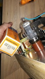
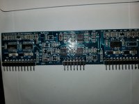
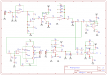
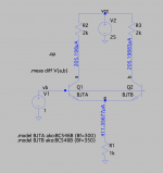
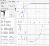
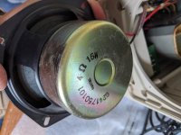
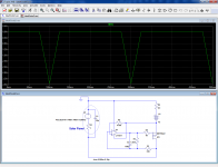
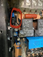
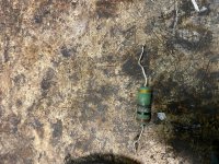
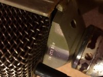
to read the numbers off the parts: it's time for me to retire! 😀
PM if you want to discuss.
Thanks

IMG_5045.jpg

IMG_5046.jpg

IMG_5044.jpg

Factory Amp Question

Hello,
I have a 2007 Pontiac G6 GT with the Monsoon system. At some point in the future, I plan to rip out the entire factory system and replace it with something that has Bluetooth. For now, I'm stuck with the factory head unit & amp. The amp splits the rear output into a woofer & tweeter signal. Wouldn't be an issue but the prior owner ripped the shockingly expensive factory speakers out and I don't want to shell out $100 apiece for them. My question is, is it possible to combine the woofer & tweeter signal coming from the factory amp into a single signal I can run into replacement speakers so I at least have some sound coming out the back until I can swap in my already owned Pioneer head unit & new front speakers?
Projects by fanatics, for fanatics
Get answers and advice for everyone wanting to learn the art of audio.
Join the Community
507,748
Members
7,886,493
Messages

Filter

Forum Statistics

Threads
406,156
Messages
7,886,493
Members
507,748
Latest member
ch5588