Occasional low frequency problem

Hello all, this is my first post here.

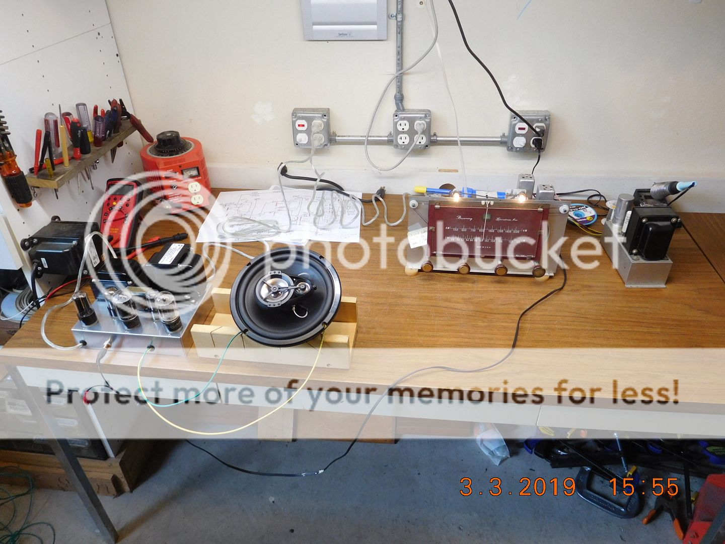
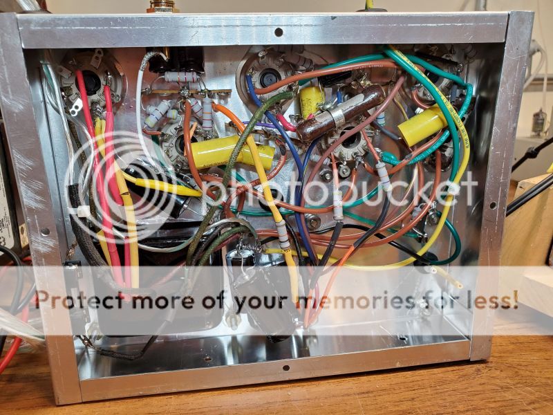
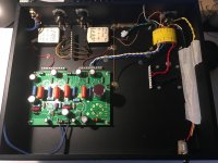
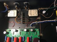
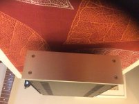
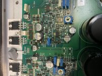
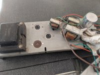
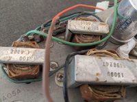
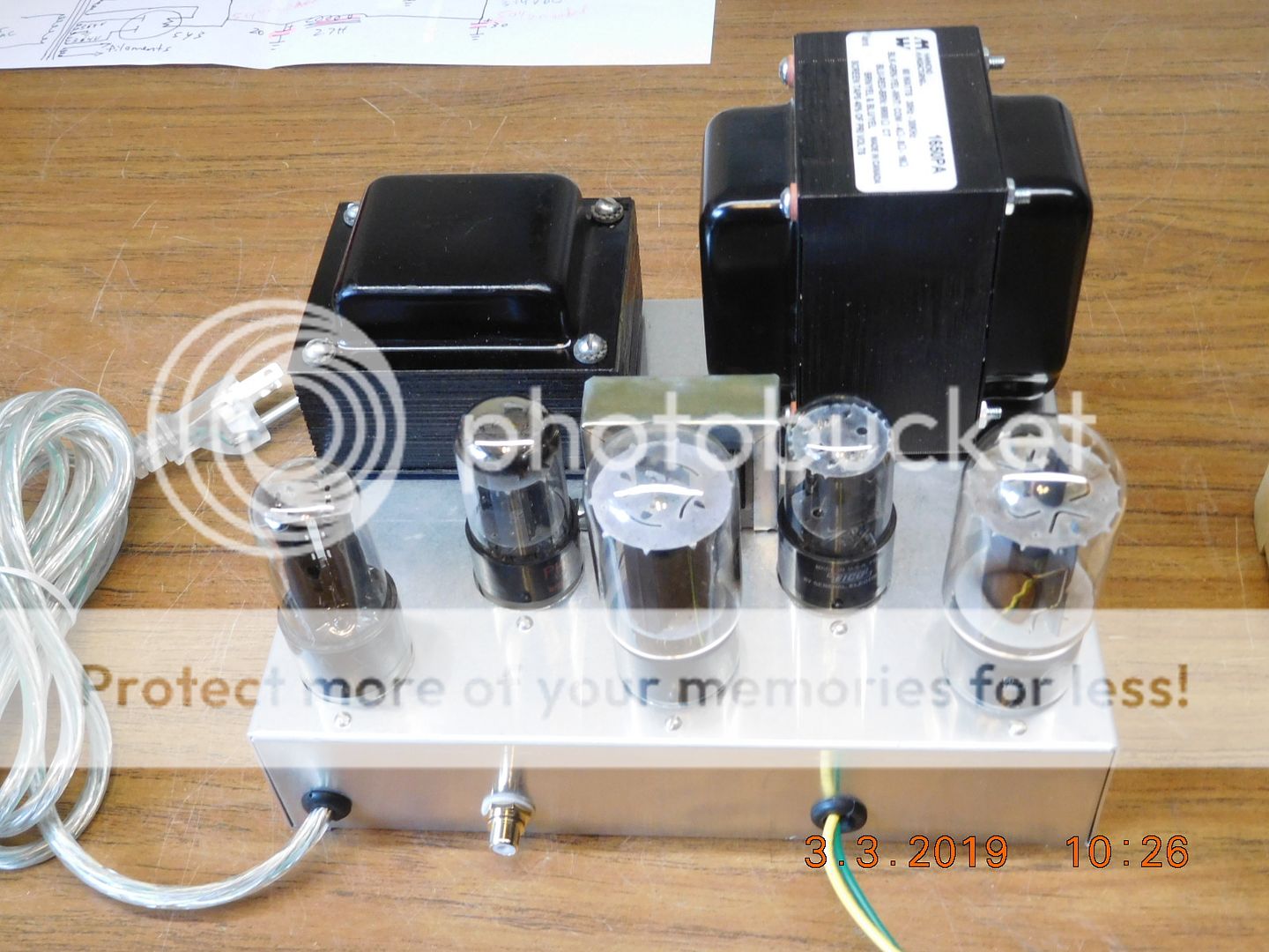
I bought a nice 1952 Browning RJ-12B tuner several years ago, so decided to build an amplifier and make a radio. I started with a power transformer from a Stromberg-Carlson radio, but bought a nice new audio output transformer. The amplifier works and sound nice, but every now and then it will put out a low frequency signal (even with no input) which causes the low frequency speaker cone to move back and forth at what I timed to be 1 or 2 cycles per second. Any suggestions?

Yesterday, I changed the input filter capacitor to 40 MFD, but that did not help.


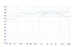
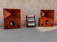
With the Browning tuner and Renegade speaker I intended to use:


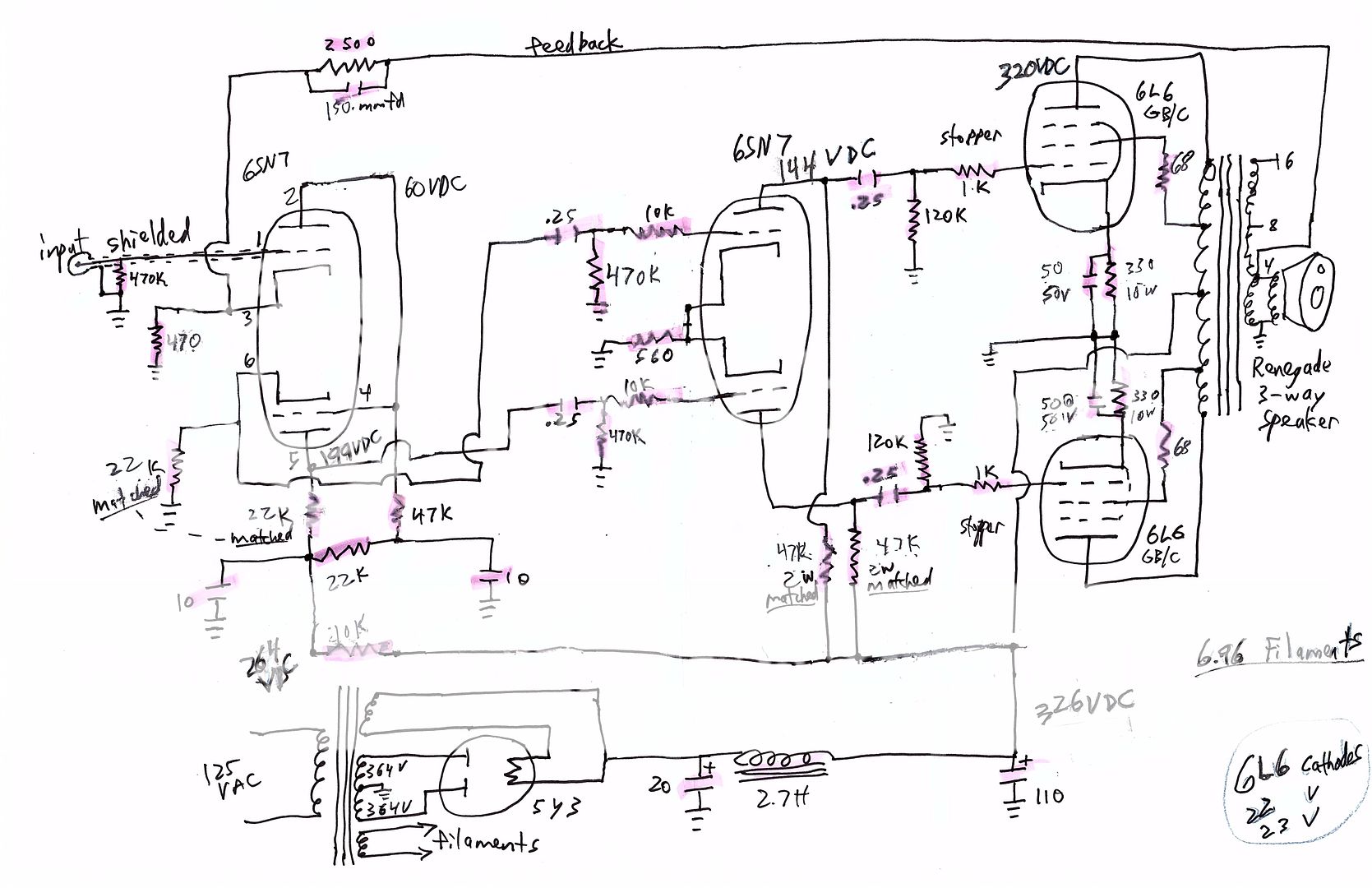
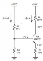
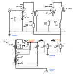
The schematic


Testing a # 46 tube?

I have a few gorgeous nos RCA Radiotron/Cunningham # 46 tubes. I have three testers, a Hickok 600a, a Hickok 550X and a Mighty Mite V.

I know how to test a tube of course but the problem is that none of my testers has data for a 46. In fact they don't have data for any of my globes. I need that data to test them but I don't know where to look. I searched but did not find anything.


Thank you

FS: Iconic speakers

SOLD: Iconic speakers

Now that I have your attention ...

A piece of me died inside today listing these but I am recently an open baffle "convert" and I don't have the room to properly store these. It would be a shame to store either of these speakers anyway!

There is no point typing everything twice and taking up server space with pictures so I will link my FB ads.

1. Snell Type-E/II's in walnut. Sequential SN's, ALL original (disabled rear ambience tweeter) and DIY stands.

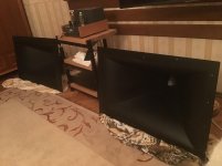
2. HIGHLY-modified Klipschorns. Crites cast woofers, Eliptrac tweeter w/B&C DE10s, ALK CSW crossovers, Rosewood veneer

Due to size and weight, I will not ship. Please contact me if you want to audition them.

SOLD

Mystery Peerless Tranformer

I have an old Peerless/Altec transformer with part of the label missing. The part that is there states it is a Type B-1... Unfortunately the rest of the part number is missing. I've looked through their catalogues from the era I believe it is from (50's) and there is no 'B' prefix letter id to be found.


Any ideas?


I'll try to take some photos in the next few days...

Bridge Rectifier vs. Schottky Diodes for F4

This is the last item I need to add to my parts order for building an F4, so I need to make a decision between using the universal PSU with Schottky diodes or a bridge rectifier block.

I built my F5 using the diyAudio Universal PSU with Schottky Diodes.

I'm leaning towards the rectifier block as it saves space in a 4U chassis, and the easy of installation.

I just wonder if I'm giving anything up?

Magnet to Magnet

Hey everyone,

I was wondering, is it possible to place two speakers magnet to magnet (back to back) using the same enclosure?

So

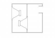
Speaker 1 is placed on the baffle and its magnet is inside the enclosure, that enclosure is closed off by a panel, in that panel is speaker 2, facing with its magnet to the other speakers magnet.

Is this possible and does it bring any problems with it?
What things should i look for and watch out for?

Ive attached a sketch of the scenario

Attachments

  • speaker.jpg
    speaker.jpg
    253.3 KB · Views: 240

Raspberry Pi + CirrusLogic Audio Card = FAIL

Anybody had luck building a decent music rendering system out of the Raspberry Pi plus a Wolfson / CirrusLogic Audio Card? My efforts have been a disappointing FAIL.

I'm trying to build a simple media rendering device out of a Raspberry Pi. I know, I know, it may not be the most HiFi solution to the rendering problem, but for this application I'd be content if I could get something up and running that works like a Squeezebox and has passable audio quality for non-critical applications.

The inherent audio system of the RPi (analog output) is well known to be just awful. My experiments were in line with everyone else's in that regard -- the result was lots of cracks, skips and pops. It was a total failure.

Things looked encouraging when Newark Electronics / Element14 in the USA started to co-market the CirrusLogic (formerly Wolfson) Audio Card. I'm in the US, and having a local distributor like Newark / Element14 seemed like it would solve some of the accessibility problems involved in ordering parts from the UK.

The CirrusLogic (Wolfson) card seemed like a decent option, but so far all of my efforts have resulted in failure. I'm wondering if anyone else has gotten the combination to work, and if so, how they've done it.

My first effort was to buy a new Raspberry Pi 2 (quadcore) device and a copy of the latest CirrusLogic Audio Card from Newark/Element14.

When I bought the CirrusLogic card, Element14 was marketing it as being compatible with the RPi 2, but they stopped advertising it as being RPi-2 compatible when it became evident that it was only pin-compatible as a plug-on card, and was not software compatible.

The problem, as discussed on the Element14 site, is that CirrusLogic still hasn't done their job of writing the ARM-7 compatible drivers for the quadcore RPi-2. At this point in time, the software support for the hardware on RPi-2 remains vaporware, which has resulted in quite a few disgruntled customers.

Community: Cirrus Logic Audio Card | element14

My second effort was to fall back to installing the CirrusLogic Audio Card on a Raspberry Pi B+.

Since the audio card wouldn't work with the ARM-7 quadcore RPi-2, I decided to use the ARM-6 RPi B+ as a fall-back option. Element14 is still advertising these products as being compatible. Unfortunately, my efforts to get the card up and running on the single-core RPi B+ haven't fared much better:

With the B+ I've found it impossible to build the kernel drivers, largely due to the fact that the manufacturer's wiki article is poorly written and contains enough errors to force the effort to result in a FAIL.

Has anybody had luck in getting the Wolfson or the CirrusLogic Audio Cards to work as a rendering device on the Raspberry Pi? I'm having a bear of a time getting the hardware/software to work, and I'd really like to know if anyone has been successful in doing it.

If you have been successful, please let me know whether you've been happy with the quality of the audio output and the usefulness of the device as a music renderer. I'm hoping to find out if it's possible to succeed in the task that I'm trying to accomplish, whether the functionality and sound quality are worth the additional time and effort that's going to be required to get it to work, or if I should just fall back and punt.

TIA.
I need some new woofers

I'm working on a 2-way system using a stack of 4 5" woofers in a 50L box. My initial choice for the drivers was poor, and I've given up trying to get them to work. They have an aluminum cone and sound like a pie plate. I'm using the miniDSP-HD in an active crossover system and have tried all manner of EQ.
I have my eye on the Silver Flute W14RC25-08 as a low cost option and the SB Acoustics SB15NRX30-8. I like the low VC inductance of the latter, but it is pricey.

I've also just come across many Peerless options; maybe the TPY05W08O0088, Heritage.

I'm looking for any comments on these specific drivers or any other suggestions.

Thanks,

Chris

Having cabinets CNC cut for you - experience, costs?

I built a kit from Madisound, which most importantly came with 'prefect' CNC cut panels which allowed for easy (and perfect) assembly. At $130/cabinet (before discounts for the kit), it seemed obvious they did a big run and were able to get some efficiencies.

Is it common to get plans and have a shop CNC cut material of your choosing for just one single pair?

I think it is less an issue of a shop that 'can' do it vs. one that will do it for anything approaching a reasonable cost. For a modest pair of small towers, I imagine you will pay a bare minimum of $200 on top of the materials. Further, if you brought them a design, it would need to be translated into a file the CNC machine could use (so maybe minimum of an hour of billable labor on top of the actual build time)?

To be clear, only talking about getting the pieces cut, not an assembled cabinet.

Output

Hi,

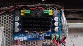
I have this TPA3116 board. Why are the speaker outputs both at 12V relative to the ground input? I've done some gain and input circuit mods but this isn't normal? Running it at 24V with a switching power supply. Otherwise it works well but just noticed this. The + and - speaker outputs are mV as you would expect, but both +12 relative to ground and input voltage!

any ideas??

Thanks,

Thei

Attachments

  • IMG_20200623_163202.jpg
    IMG_20200623_163202.jpg
    743.3 KB · Views: 117

Speaker Recommendation

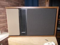
Current system: Akitika PR-102 preamp and GT-102 power amp with Bose Interaudio 4000 speakers. I'm currently considering 3 sets of speakers for my next upgrade, and would like to know if driving any of these with the Akitikas would be asking for trouble. Also if one jumps out as a much better fit than the others, since I won't be able to hear the last two before making a purchase.

Option 1: A pair of nicely reconditioned JBL L100 speakers from a friend. They were put in nice wood cabinets about a year ago and got everything that needs to be replaced over time upgraded, so they sound better than new. They'll be about $2500 plus 5 hours in the car with the friends and family discount.

Option 2: A pair of Polk LSiM707 since it's that time of the year for Polk's half off sale. After tax (grrrr) that'll be about $2150 for the pair. This seems to be the most questionable for whether or not the Akitika will drive it. I seem to remember reading that these needed a beefy class D amp somewhere, but I could be thinking of something else.

Option 3: Save some more money and get a really pretty Seas Odin pair as pictured on Madisound instead of one of these. Seas Odin Speaker Kit - PAIR

Parasound HCA 806 with some bad channels

My Parasound HCA806 has at least 3 bad channels. The symptom is a heavily distorted sound.

I have done quite a lot of basic electronics repair over the years so I'd like to try my hand at fixing it. I have a few questions:

1) It seems like the capacitors are the common problem in old solid state amps. Should I just go ahead and replace them in one of the bad channels as a first step? What model of capacitor should I buy?

2) I couldn't find schematics for this one, but I have them for the 800 and 855. Is anyone here familiar enough with Parasound to know if these will be helpful (or even better, does anyone here have the 806 service manual or schematics)?

3) Should I let the amp sit for awhile before opening it up? I have read that if you're not careful, amplifiers can discharge quite a lot of electrons even when they are unplugged.


Thanks!
Mark

Whaferdale Pro S-1500

Hi


Does anyone know what is the bias setting for this amp. There are 3 trim pots, VR4,VR5 and VR6 on each power amp board, no information is given on the schematic on the bias settings. I guess that VR6 is for biasing and VR4 and VR5 for DC offset. I have replaced some blown power transistors on each channel. I did not rebias after replacing the transistors, but using the preset bias. After leaving the amp ON for 2hrs, the left channel feels warm but the right channel is hot. Please assist. Schematic attached.


Thanks

Attachments

  • Locked
Global Movement to shift manufacturing from China to Elsewhere

Hi Friends,

I am an Indian Resident. As we all know that agter COVID-19, World is changing rapidly and this might lead to averting of purchaser countries to import from China. This will definitely be an opportunity for some other country to begin manufacturing facility.

I am just creating this thread to access effect of this polorization.

B&W ASW 855 turning off when heat up

Hi, I got my hand on cheap B&W sub that plays pretty nice bass but when played out loud or for long time, it turns itself off. After letting it cool down and turning it back up it plays like nothing happened.

I guess its overheating because thermal connection between parts and heatsinks are bad after all those years of usage. But I am no amplifier expert, I know my basics, can build stuff from kits and so. So just to be sure - is there any other reason for class D amp to turn itself off other than heat?

Thanks to you all kind people

LTSpice KT88 model problem, or schematic?

While I'm waiting for my transformers to come in, I thought I would give LTSpice another shot and play around with some values. I had some trouble with the 12AX7 model in the past, but worked it out. Now I'm trying a KT88 and I'm not really sure what I'm looking at here.

An externally hosted image should be here but it was not working when we last tested it.


Basically I am getting -223KV on the grid. I played around with different values(which is why some of them might seem wacky) to try to get the grid to "move" to see why it's doing this. I detached the signal just in case it was coming from that somehow(impossible with the cap).

Is there something obviously wrong with my schematic or is my KT88 model borked? Someone else on this board had a similar problem, which they fixed by renaming the symbol's pins to match the model. This did not seem to help.

AudioStatic ES-100 power

Hi,


I just bought a second hand AudioStatic ES-100 print. It has 2 wires for power supply connection, but I'm not sure what voltage to connect. Can I connect it straight to the mains (220V, Europe), or is it a lower voltage like 12 V? When watching photos, I see just a wire from the rear of the ES-100, but I've read about 120 / 12 V power supplies for the ES-100 on this forum. I wasn't able to find a schematic of the ES-100, only for the ES-100, where a 9V voltage input is printed.


Kind regards, Jeroen

Cubo Kick 15 measurements

I apologize if I have overlooked it, but I couldn't find measurements of the Cubo Kick 15 design anywhere, so I thought I'd post them here.

The bin has been built according to the available plans on freespeakerplans.com, but with 18mm poplar multiplex, which was on hand. This makes it VERY light, but it needs some more reinforcements (which we still have to implement). It is loaded with the 18 Sound 15ND930, 8 ohms.

Measurement is with 2.83V at 1m, mic on the ground, measured outside, 2pi.

THD seems a little high 😱. We'll reinforce the cab and do some more measurements.

Attachments

  • Kickbin 1 SPL.png
    Kickbin 1 SPL.png
    57.8 KB · Views: 588
  • Kickbin 1 Impedance.png
    Kickbin 1 Impedance.png
    37.6 KB · Views: 499
  • Kickbin 1 THD.png
    Kickbin 1 THD.png
    149.8 KB · Views: 524

My second Tubelab Simple PP! A pentoad Frog!

Working on my second simple pp! The first one was set up in triode mode and this one will have pentode outputs with a regulated screen supply.

I am thinking a pair of stacked glowtubes would suffice for a screen supply and look pretty...

The outputs are a pair from stancor out of a Heathkit AA-100 that are 7kpp with 0-4-8-16 secondaries.

Its coming along...

Attachments

  • IMG_5258.jpg
    IMG_5258.jpg
    877.7 KB · Views: 484
  • IMG_5259.jpg
    IMG_5259.jpg
    924 KB · Views: 481

Western electric compression driver clones

Good day
Currently i have pretty good modern hybrid system with radian 950+k402 on top and bass reflex low section.
But i`m going to grow a bit)
I`d like to try something like western electric 555 driver + we15 horn, but originals are too expensive for me and i`m a bit scared of 5 watt maximum power handling.
Horns aren`t a problem because there are people in my country (Ukraine) that are making we15 clones for much cheaper. The main difficulty are drivers.
I am looking at clones like lamar audio and G.I.P.( don`t know more, maybe you can recommend other).
And i have a few questions:
1)Maybe someone was able to hear them and can tell me how do they compare with original we555 and more modern drivers?
2)If someone used such a deep horn, how did you manage with time delay between woofer and driver?
3)I have read Geddes and many other literature about horns and all of them share the same opinion that such a long horn can`t sound good. Is it true? I have no possibility to listen them, aren`t they just a cool vintage stuff that sounds bad?
Would be very grateful for any thoughts of more experienced colleagues
  • Like
Reactions: David Whistance

Akitika gear "can't" have XLR?

I shot an email to Dan at Akitika and told me that you "can't" have balanced input/output on the PR-102 or balanced input on the GT-102, but didn't get anything back when I asked why not. Does "can't" mean he doesn't want to mess with and/or support it, or is there some design limitation that prevents anything other than RCA from being used?


In principle it sounds doable. Remove the RCA jacks, drill a bigger hole (probably limited to one input and output on the preamp due to the proximity of the jacks) and drop in the new XLR. Am I oversimplifying and missing something obvious? I ended up getting the preamp and power amp second hand so I didn't do the builds on these.


Sooo...XLR on Akitika. Anyone actually done it and can confirm that's it's possible? 🙂

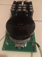
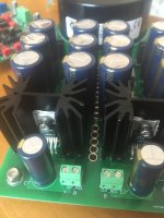
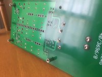
FS dual lt3081 voltage regulator pcb & lt3081/lt3091 bipolar power supply pcb

Hi,

As the title says I am selling 6pcbs(3 of each kind).
Both pcbs, the dual and the bipolar are the same dimmensions and have the same mouting holes.

Some details about them
102.54mm * 251.44mm ;
Layers: 2;
PCB Thickness: 1.6mm;
PCB Color: Green;
Surface Finish: Hasl;
Copper Weight: 1;

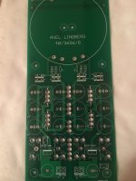
The boards are designed to be used with avel lindberg 50VA incapsulated transformers.
Transformer input is configured only for 240Vac input.

The dual lt3081 pcb has 2x lt3081 each one connected to a secondary winding of the transformer, completely independent between them.
The bipolar lt3081/lt3091 pcb has one piece of each reg and these are connected each one to a secondary winding of the transformer thus isolated between them also.

I will describe in short what is on the pcbs.
We have ac line in, fuse, transformer primary.Since I have opted for screened transformers I have connected the transformers screen to ac earth as suggested by avel lindberg.
After the transformer I have c rc network to eliminate rectifier diode ringing.I can supply the values of the components for these networks for the 50va 2x20V and 50va 2x12V transformers.
Next are the rectifier diodes, after them a crc filter and finally the lt's.
For the lt's I have included a 1206 smd resistor to setup output voltage, or you can use a pot which has also it's own place on the board.

In the first photo you can see the bipolar pcb. If you look on the bottom you will see the outputs which are signed as out_pos and out_neg.
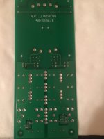
Second photo is the bipolar pcb bottom.
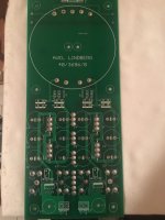
Third photo is the dual ps pcb.
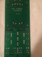
Fourth photo is the dual pcb bottom.
Fifth photo shows the bipolar ps front side.
Sixth photo shows the dual ps powering a b3se dac and cronus reclocker.
Seventh photo show the back of the bipolar ps.
Eighth photo shows bottom of the bipolar ps.
Nineth photo shows the bipolar ps near a legto iv stage which was powering with succes.

All boards are sold


Thanks.

Attachments

  • image1.JPG
    image1.JPG
    647.3 KB · Views: 1,013
  • image2.JPG
    image2.JPG
    564.8 KB · Views: 873
  • image3.JPG
    image3.JPG
    613.9 KB · Views: 835
  • image4.JPG
    image4.JPG
    564.4 KB · Views: 812
  • image5.JPG
    image5.JPG
    555 KB · Views: 789
  • image6.JPG
    image6.JPG
    566.9 KB · Views: 371
  • image7.JPG
    image7.JPG
    583.7 KB · Views: 394
  • image8.JPG
    image8.JPG
    741.9 KB · Views: 418
  • image9.JPG
    image9.JPG
    590.3 KB · Views: 459

High efficiency Two-way design, where to cross them

As a "thought experiment", some musings, trying to design a super high efficient two-way. The two culprits are the Audio Nirvana 15" classic ferrite, and the Aurum Cantus G3...
By plotting the two together, my best guess is a first order for the AN 15 at about 2K, so by 4K it has tamed that rising response, dragging down that hot spot 6Dbs worth...what do you guys think?


----------------------------------------------------------------------Rick........

Attachments

  • Audio Nirvana AND Aurum Cantus together.jpg
    Audio Nirvana AND Aurum Cantus together.jpg
    100.4 KB · Views: 469

Best "bang for the buck"5 inch full range is?

Hi Gentlemen,
I am delighted with my just finished Alpair 10P speakers. I have built several smaller full rangers using Tang band 4 inch drivers in the past and liked them pretty well, but the Alpairs are in a whole different league. I would like to turn a couple of friends on to this full range experience, but dont want to spend more than necessary on the builds since I'll be gifting them.
A while back forum resident XRK, who is very knowledgeable, suggested that on a super low budget the Dayton Audio PA 130 would work well for the price. I built a pair, and while they were not bad they had little to none of the "magic" I hear in the 10Ps.
So, are there any full rangers that approach the bass depth, detail, and SPL levels of the 10Ps for a significantly lower price? I think I'm asking for a lot here but am hoping that there are some hidden gems out there.

Best,
Jay

Valve ( tube ) Characteristic Tester.

I have no idea if anybody has posted this before but if anybody has the time and patience its not too hard to build .


Keep in mind this is a "proper " tube tester in that it employs a Wein bridge oscillator to test the tube .


The circuit is available in issues of ETI magazine -


Volume 26-number 8 and volume 26- number 10.


It can be accessed on that wonderful American radio heritage website -


RADIO and BROADCAST HISTORY library with thousands of books and magazines

Design Stable @ 1 Ohm Nominal?

Good evening all,

I am experimenting with a Frankenstein re-build of an old pro-sound subwoofer. The only voice coil I could find so far is from the car audio world, and is rated at a disturbing 1 ohms nominal impedance.

Do any of you know of a module or proven design which is stable at such a load? I thought of using a car audio amplifier, but it seems a shame to step the mains voltage down to 13.5 or whatever, only to have the power supply in the mobile amp step it back up. North of 500 watts RMS if possible!

Thanks for your help,

JF

Impedance of two drivers at their crossover cut-off?

Hello,

I'm using this site for rapid crossover simulation of two raw drivers : Speaker Crossover Calculators by V-Cap I like the possibiity to enter the impedance of the high pass and low pass for each driver.

I please have a question about these two impedance : should it be the impedance of each standalone at the precise cut-off frequency or the average Re (voice coil resistance) given in the datasheet... Or the lowest impedance point where the impedance curves meet each others in frequency ? I.E : the impedance at cut-off of the weakest Z of the two drivers cause this is what see first an amp!

Just for illustration : 2 bass driver, 2x 8 ohms with a Re of 7.8 ohms , chosen cut-off : 300 hz, here the impedance of the two // drivers measured raw is not half of the 7.8, i.e 3.9 ohms but 3.4 ohms.
The mid driver ha a Re of 7 ohms and at 300 hz the impedance curve is 6.5 ohms.


Sould I putt in the calculator at 300 hz : low pass : 3.4 ohms and high-pass:6.5 ohms or should I simply enter the average Re of each drivers given in the data sheet : 7.8/2 for the 2 bass : 3.9 ohms and 7 ohms for the high pass for the mid driver ? Or I enter the lowest impedance for the high and low pass cause electicaly this is where it goes : 3.4 ohms


The question is for passive XO but I ask for active crossover as well : has the exact impedance at Xo cut-off to be entered in the soft parameters as well or just the average Re of the drivers.


Many thanks.

Inductor or resistor?!

Hi this is my first post in this forum. I am trying to restore a pair of German made ALR Nummer 4 speakers which I picked used. There is a crossover board inside which for the midrange and the tweeter and a separate board for two woofers. On the mid-tweeter board, there are two components which looks like resistors but had 47RJ written on them. They are as big as a 3W resistor. are these resistors or 4.7uH inductors ?? How can I find it? I replaced them first with 3W carbonresistors and sound became very shouty which is not at all close to the working pair I have. But when I used a 0.82ohm small 0.25W resistor it sounds close to the good speaker which made me think this was an inductor more than a resistor.

What is the difference between wirewound resistor with value 4R7 and inductor 4R7?

Mono sub channel summation

When we're talking about active crossovers, setting the gain is pretty straightforward when we're talking mid-to-high frequencies; just give the stereo channels a flat response. But I have a question about what happens when you have a mono sub. Do you make it so that the sensitivity of the mono channel is (up to) 6 dB higher because there is only a single channel, or match the sensitivity with the stereo channels because the summed signal will automatically be at a higher voltage and result in the appropriate higher SPL? I'm leaning toward the latter but would like to hear others' opinions/facts.

CGR Mar-Kan 10.3 Question

In fear of too much bass in my room I changed my mind and want to build the CGR Mar-Ken instead of the Pensil for the 10.3. My old (2005) Seas 21cm bass was too deep & mighty for my room.
I think the CGR Mar-Ken or BR will show more 3D/soundstage and detail than the Pensil.
The question is: Can I transfer the vent to the back? I cant see any problem doing that....or?
Thanks in advance.

My 3-way horn system

Good day to all
Finally i have bought all drivers and horns for my system so i can start building theme
Here is the list what i have:
HF- faital HF10AK+ STH100 HORN
MID- Radian 950 + klipsch k402 horn
LF- faital 15pr400
I will use passive crossover, targets are 600hz@12db and 6000@6db
Autotransformers will be used instead of l-pads, maybe i’ll go with active crossover someday
I have a few questions :
1) displacement between radian and woofer will be about 40cm
If i will put drivers and woofers in phase, will I hear time delay?
I found passive crossover time delay scheme but it is very difficult
2) what is the best placement for HF10ak?( maybe in LF- section?)
Also i’m considering about making fronthorn enclosure like in tad 2301 to minimize drivers distance
Thanks in advance
With best regards, Andrew

Attachments

  • 388998FC-EEC1-4032-8FAF-98F04BF7B414.jpeg
    388998FC-EEC1-4032-8FAF-98F04BF7B414.jpeg
    86.3 KB · Views: 1,662
  • B4AD15BE-89DE-4A4E-A690-3FA758B1C74C.jpg
    B4AD15BE-89DE-4A4E-A690-3FA758B1C74C.jpg
    681.1 KB · Views: 1,537

Plate to plate vs cathode to cathode - load impedance

Say we have a pair of beam tetrodes that need a load impedance of 8K plate to plate. Then we decide to put the centre tapped output tranny in the cathode circuit instead. Would the right load still be 8K? Obviously the circuit would have a lower output impedance, but it can still only pull the same peak current as before, so what's the go with selecting the right load?

C-Audio RA501

Hello,

Would any of you be so kind as to point me to some info/schematics about the old C-Audio RA501? I've recently purchased one of them, and it ha intermittent errors on one channel. After taking into account the low level of local audio techs, I'd rather provide them at least with schematics.

Thanks in advance for any possible help?

Cheers,
Mihai Toma

Denon PMA-S10II

Hi,
I have this amplifier but it has a problem now with DC on speaker output.
When i turn voulume up i see with my voltmeter there is DC voltage on outputterminals.At 40% volume i hear rele clicks and DC drops to zero.
Is amplifier totally damaged or is it the preamppart.
I need a servicemanual to find out were DC occurs in signal.
Any good advice?

Thanks,

SPDIF to I2S Converter Group Buy

All,

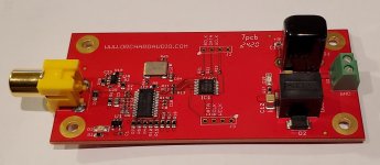
I have designed an SPDIF to I2S converter based on the CS8416 in hardware mode.

It supports up to 24 bit / 192kHz, while automatically adjusting to all standard sample rates and 16 / 24bit operation.

It can come in two varieties:
1. It can be powered from 17 to 72V and provide an auxiliary PS with 12V 800mA output.
2. In can be powered from 6 to 28V and provide no auxiliary PS.

The board also has a feature to bypass the I2S from CS8416 with an external I2S bus. When SPDIF is not present the secondary I2S bus is routed to the output.

Prices as follows
$200 if 10 people purchase with 14-72V input
$150 if 20 people purchase with 14-72V input
$130 if 30 people purchase with 14-72V input

$170 if 10 people purchase with 6-28V input
$120 if 20 people purchase with 6-28V input
$110 if 30 people purchase with 6-28V input

PCBs are high quality 2 layer boards with ENIG finish and use only high-quality components. Boards are manufactured and assembled in Canada.

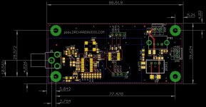
See attachments for board sizes and pictures. Dimensions in mm.

Thanks for your time.

Leo

Attachments

  • Front.jpg
    Front.jpg
    454.5 KB · Views: 142
  • Back.jpg
    Back.jpg
    461.2 KB · Views: 142
  • dimensions.jpg
    dimensions.jpg
    167.4 KB · Views: 148

Toshiba DVD disc error

Hello, I have a Toshiba SD900e (it may apply also to SD9200 SD9500 SD9000) which reads DVD's but not CD's. I don't know if there is a general reason for this: such as DVD read speed is different to CD or whatever... it's very odd altogether because if it's a mecanism problem it should also affect the DVD? same applies if it's a laser lens problem?😕
I've googled and read several "solutions" for disc error issues at other forums but its doesn't make sence to me if dvd works and cd not...
And then there is the "firmware" which I hear that it should be upgraded...but don't even know how to acces to "toshiba's OS".
I really appreciate your help if you can share your thoughts about this issue.
Also I'm trying to find the laser lens replacement.
Thanks!!

A case where measurements go ????

Hi all.

if any are familiar with my posts, you might equate me to a measurement guy, and a FIR processing guy.
Rightfully so, cause i am, to the bone. Most of the time, i think i can make anything sound very close to anything.

I thought i should post a case where despite the fact the only change in the speaker was a pair of drivers that were swapped with pretty close equivalents,
and then tuned to exactly the same on-axis mag and phase traces,
.......and i do mean exactly the same mag and phase traces....
well, the sound is oh so different.

I've always attributed a sound difference when on-axis traces are identical, to off-axis differences, and how that creates a different power response interacting with the room.

But in the case i'm writing about, it was simply two different 10" drivers mounted in the same synergy horn, firing through the same ports.
And on-axis traces for the two sets were exactly the same....EXACTLY 🙂

Yet, what a diff...listening both indoors and out.
10 Fe200's, and 10PR300's , in the synergy.
The 10FE200's are loose and soft sounding compared to,
the 10 PR300's sounding tighter and righter.
I'm guessing the motor strength difference between the two is the thing, firing into a port that constitutes a 10:1 compression ratio.
Dunno....???
Can't be a power response difference it seems, given the same horn, same ports, same measurements....
Measurements were made at about 90dB @ 1m, so can't see it as a low level vs high level issue. Multiple measurements...pretty sure no error....
Ideas?

So the point here, of this post, is the 10FE200 and 10PR300 have identical looking transfer functions and impulses, pretty much textbook perfect, along with the whole speaker response.
And again, can there be a power response difference?

I don't often encounter a clear situation where it measures the same, but sounds so different ...
Thought in fairness to all my posts about measurements, FIR, and replication, i should throw this confusing experience out there.....

nuforce amp board hypex (or any other brand psu)

Hi
I am a completely newbie so this might be a really dumb question but anywho... I upgraded a pair of nuforce amplifiers recently that left me with 2 unused ampboards that I thought I could use to build a descent stereo-amp with if possible! So my question is can I use a psu from another manufacturer (like hypex) or do I need to stick to the psu made originally for that ampboard? Is there any particulars that I need to check to see if they are compliant or is it:"just forget about it!".
These ampboards are load invariant (dunno if that makes a difference)
Regards
/Johan

Various drivers

I've got various drivers from my DIY days before I set up KJF audio in the UK. I've only used all of these drivers for testing,in fact most of them have never been used. If I have used them I have stated.

Photos can be sent. Postage will happen Via UPS insured, I'll just pass on the cost.

2 X seas W22NY001 E0045 Excel series woofers -£165 each plus delivery.

3 X SB acoustics SB15NRXC30-8 -£35 each plus delivery

Pair Cotswold audio BMR drivers BMR85DD N4Y £40 the pair plus shipping.

Pair scan speak 2606/920000 tweeters £40 plus shipping

Pair Vifa DX25TG05-04 tweeters £40 plus shipping

Pair scan speak R2004/6020X1 tweeters £160 plus shipping

Pair ScanSpeak D3004/662001 tweeters these are used so show some signs of wear around the bolt holes. They are however fully refurbished with new butterfly by ScanSpeak. These are the best drivers I ever owned. £275 plus shipping

1 Peerless by Tymphany XLS 830452 10inch XLS subwoofer. £110 plus shipping

Help: Excessive B+

In my newly assembled monoblock (see schematic below), heaters voltage for all tubes measure correctly. So, I just powered the B+ for the first time. Vac is measuring 1,000 Vac across the the 2 primary wires. The power transformer is rated 500-0-500. Vdc is measuring 638Vdc directly after the 83 rectifier tube and before the LCLC filter. Vdc is measured from the 83's hot filament and ground. The 83 rectifier is supposed to drop 15Vdc. So, not sure why it's measuring 638Vdc.

Then, I measured 630Vdc after the LCLC filter. Using PSUD, rectified power should be around 495Vdc, not 638Vdc.

Note: Not sure it matters, the driver and output tubes are not inserted, so there is no load.

Thoughts?

Attachments

  • C3g-45B v7.1 ground.png
    C3g-45B v7.1 ground.png
    96.9 KB · Views: 309

Music video clip that I can't remember and try to find, I'm waiting for your help

Hello friends, I do not know if I opened the right place, if not, just excuse me. and sorry for my poor English, I use google translate.

The clip I was looking for is like 2000 (+10 -5 years) and I am looking for a clip that I saw in the music program on TV. As far as I can remember;

1- Alternative rock, Alternative pop can be, for example, smashing pumpkins or green day etc comes to my mind, but I have looked roughly, did not come out of them, or I missed it.

2- The main tip: There are a lot of guys chasing a man in the clip (as if they might be like a matrix-like suit and an agent) and they are running up from the skyscraper or a building surface during a chase (the surface may be glass building), the most specific element of the clip is in this mind remaining.

I searched according to these criteria, but there is no place to examine the bottomless well, the subject of the clip that I will find

I am waiting for your help and thank you in advance.

Covering back of woofer with material

Quick question - Joe Akroyd of Royd audio, covered the back of the midbass drivers with some kind of material. I've read about this technique before but can't remember the details. The thing I'm most interested in is what it would do to the thiele small parameters?

I suppose I could get a driver out of the shed and do some experiments, but thought I'd ask here first (because it's easier).

DSC00937.jpg

Changing output transformers?

I picked up a Zenith KPS 80 suitcase record player and pulled the amp. The output transformers are quite small. I'm guessing the amp's output is ~2 watts per channel. I don't mind leaving things as they are, but I'm wondering if getting larger output transformers is a reasonable idea. If so, what do I need to look for, and do I need to change anything else?
It's got three output transformers; it has a larger speaker that uses the larger transformer. I'm not sure what I'll do with it, but it appears to be for added bass.
I know enough to keep myself safe and to ask questions. I'm going to change the electrolytic caps, but depending on the reply I get (or don't get), I'll decide if I'll do anything else to it down the road.
Thanks,
Mike

Attachments

  • Amp1.jpg
    Amp1.jpg
    801.5 KB · Views: 234
  • Amp2.jpg
    Amp2.jpg
    943.4 KB · Views: 242

Philips MKT 373 vs 344

Hi, I am new member here. I am currently restoring a pair of 90s German made ALR Nummer 4 speakers. By mistake I ended up breaking two caps both philips mkt 373 series- 10uF and 1uF. (100v).I tried a Audyn branded one of the same value but with higher voltage rating but they sound much more shouty than the Orginal caps. Locally only philips mkt 344 is available with a sensible price for shipping. Are they the same ?
Projects by fanatics, for fanatics
Get answers and advice for everyone wanting to learn the art of audio.
Join the Community
507,756
Members
7,886,876
Messages

Filter

Forum Statistics

Threads
406,164
Messages
7,886,876
Members
507,756
Latest member
CalmRiver