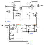
In my newly assembled monoblock (see schematic below), heaters voltage for all tubes measure correctly. So, I just powered the B+ for the first time. Vac is measuring 1,000 Vac across the the 2 primary wires. The power transformer is rated 500-0-500. Vdc is measuring 638Vdc directly after the 83 rectifier tube and before the LCLC filter. Vdc is measured from the 83's hot filament and ground. The 83 rectifier is supposed to drop 15Vdc. So, not sure why it's measuring 638Vdc.
Then, I measured 630Vdc after the LCLC filter. Using PSUD, rectified power should be around 495Vdc, not 638Vdc.
Note: Not sure it matters, the driver and output tubes are not inserted, so there is no load.
Thoughts?
Then, I measured 630Vdc after the LCLC filter. Using PSUD, rectified power should be around 495Vdc, not 638Vdc.
Note: Not sure it matters, the driver and output tubes are not inserted, so there is no load.
Thoughts?
Attachments
Try a load. Use resistance that would draw the same current as the circuit does so you don't have to risk the tubes. Depending on the stiffness of the pwr xfmr and inductor DCR, the voltage will drop quite a bit.
The load matters, this is an unregulated power supply. The voltages will vary with the loading.
Last edited:
You are using a modified cap input B+ filter (modified to have a small capacitance input). Take the 0.68uF capacitor out. It is 1950 Ohms capacitive reactance. With 50mA of load, it will have a peak to peak ripple voltage of 0.050A x 1950 Ohms = 97.5V.
The average of that is 49V.
The 83 drop is 15V.
500V x 1.414 = 707V peak, and 707 - 15 = 692V
692Vpeak - 49V = 643V.
Even without the tubes, you have a very small load, the two bleeder resistors.
With the 0.68uF cap removed, as long as you have enough load to make the first filter choke at least as large as critical inductance, and if you take the 0.68uF cap out, you will get (500V x 0.9) -15V (83 drop) = 435V, when loaded.
That is still way to much voltage for a Real 45 tube.
Perhaps you are using a modern, higher voltage, higher dissipation 45-like tube (emission labs high power model, etc.)
Critical inductance = 350/mA load
10H x mA load = 350
350/10H = 35mA.
Your mono-block has a large enough first inductor, it meets the critical inductance rule.
Of course, without the load, the B+ will be much higher (just like when you got 630VDC, pretty close to my calculations).
Also, the 83 rectifier has only 15V drop. You need a rectifier that has more drop (Try a 5Y3G with a 60V drop, the 5Y3G is a shoulder tube which matches the old 45 shoulder tubes).
Last edited:
Hi
is that really 498V on the plate of a 45? with the cathode at -87 volts and the grid at zero volts?
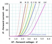
you want make your 45 go POP fast? Please look at plate curves for the 45.
I see lots of problems with this schematic... here is a suggestion: keep it simple. Please.
You can use a 100Hy plate choke on the c3g if you must. But even a Resistor can be used to start. Try just using a (inexpensive polypropylene) coupling cap to the grid of the 45. Then graduate it to IT coupling.
Resistors and caps are cheap and easy.
You want to use negative bias on the grid, not the cathode. Try the kind of values you see on the RCA specs sheet if you are not sure.
245V on the plate. Cathode at Zero. Grid at -48.5V runs around 34mA for a new-ish 45 tube. Even with resistors and caps the sound will be pretty NICE.
Ian
is that really 498V on the plate of a 45? with the cathode at -87 volts and the grid at zero volts?
you want make your 45 go POP fast? Please look at plate curves for the 45.
I see lots of problems with this schematic... here is a suggestion: keep it simple. Please.
You can use a 100Hy plate choke on the c3g if you must. But even a Resistor can be used to start. Try just using a (inexpensive polypropylene) coupling cap to the grid of the 45. Then graduate it to IT coupling.
Resistors and caps are cheap and easy.
You want to use negative bias on the grid, not the cathode. Try the kind of values you see on the RCA specs sheet if you are not sure.
245V on the plate. Cathode at Zero. Grid at -48.5V runs around 34mA for a new-ish 45 tube. Even with resistors and caps the sound will be pretty NICE.
Ian
Last edited:
is that really 498V on the plate of a 45?
It's a 45B: Emission Labs. Information about life time of electron tubes.
It looks like the OP is aiming for one of recommended operating points for this tube (see table on linked webpage).
The primary is 500-0-500 so across the two should be 1000V. After rectification you are still getting 638V right? 1.414 X 500 - the two diodes drop (maybe more) in parallel?
I will put a load on the circuit. The output tube is a 45B and yes, I am trying to utilize the recommended operating points per the EML site. I will report back tomorrow with the results once the circuit is loaded.
Thanks everyone!
Thanks everyone!
Sorry, the schematic had 45B in it.
I am too stupid to automatically know that 45B is an Emission Labs tube.
But, I ask the question, did you read my post # 4?
If you have an unloaded supply, you will get more B+ than when you load it.
If you need less B+ volts when it is loaded, then toss out the 0.68uF capacitor.
And why are you using the 83, for the glowing effect?
Without critical inductance, you would have to use a time delay on the High Voltage to the 83 until the mercury changed from cold to hot state.
I am surprised that anybody can legally ship a type 83 rectifier across city, county, state, and country borders.
I know that some carriers would refuse, if they knew what was in an 83.
A 5Y3G or other tube will work there, without the hazards (but admittedly no pretty glow).
So get a dropping resistor, and an OD3 shoulder tube. Looks pretty.
But of course, the stupid CFC lamps have mercury too.
The official US law says that if one falls on your rug and breaks, you have to open the windows and doors, wait 15 minutes before re-entering, and call the hazardous material group. They will come and remove a 3 by 3 foot section of the rug, along with the CFC lamp.
But no money was allowed by the government to actually pay for a hazardous material group.
OK team. Progress. With 1 outstanding issue so far.
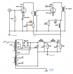
1. As was suggested by the DIYAudio respondants, the excessive B+ was caused by no load on the circuit. Now, with load, B+ after LCLC and Output tube Anode is spot on at 498Vdc. Yeah!
2. However, B+ going to the driver tube is also 498Vdc. Per the attached schematic, the black measurements points are the target and the orange are actual. So, after the 18.4K resistor, B+ "should" be reduced to 240V from 498V. Currently, the measured B+ after the 18.4K resistor is 498V. So, there is no voltage reduction due to the resistor. The resistor measured at 18.5K. Thoughts on why no voltage drop?
3. The -2.5V bias LED on the C3g driver tube is not illuminating.
Note: the 100K input resistor and LED both terminate at the C3g ground post in the middle of the tube. Then, the ground wire is connected to the C3g ground post which provides ground for the C3g metal shield and in my case, also provides ground for the 100K input resistor and LED. Wondering out loud if this is the correct thing to do or not?
Thanks, Pat
Attachments
Did you forget to connect the C3G Screen?
It is not even shown in the schematic.
Follow a bad schematic, and get bad results.
No Screen voltage, equals no plate current, equals no drop across the 18.4k resistor, equals 498V on the C3G plate.
Yes?
No?
Yes, my mistake is I did not call out your schematic error at an earlier time.
We (I) do not have the luxury of having a C3G here in the US, so I have to remind myself that it is a Pentode.
Last edited:
An even more basic question: do you have the C3G plugged in? I ask b/c above you indicated that you were trying to test the power supply without tubes.
To paraphrase 6A3Summer: no tube = open circuit = no current = 498V after the 18.4K resistor.
If you are trying to test the power supply without tubes, I think you need a load that mimics the C3G tube.
cheers, Derek
To paraphrase 6A3Summer: no tube = open circuit = no current = 498V after the 18.4K resistor.
If you are trying to test the power supply without tubes, I think you need a load that mimics the C3G tube.
cheers, Derek
Did you forget to connect the C3G Screen?
It is not even shown in the schematic.
Follow a bad schematic, and get bad results.
No Screen voltage, equals no plate current, equals no drop across the 18.4k resistor, equals 498V on the C3G plate.
Yes?
No?
This is my first use with a pentode, so I need a bit of help here. There are 3 grids in the C3g (C3g pin out image attached). G1 is connected to the input signal. G2 and G3 are not connected to anything, so this explains why there is not voltage drop. I was hoping to use the C3g in Triode mode instead of pentode. That said, here is what I propose:
G2 connects to Anode
G3 connects to Ground
Sound correct?
Thanks
Attachments

An even more basic question: do you have the C3G plugged in?
hi Derek, Yes, the C3g is plugged in. Thanks, pat
You have to decide if you want to use the C3G as a pentode, or use the C3G in Triode Wired mode.
Because you are using an interstage transformer, I suggest you use the C3G in Triode Wired mode.
Connect G2 to a 100 Ohm resistor, and the other end of the 100 Ohm resistor to the C3G plate.
G3 is Internally connected to the Shield (You already said that you connected the shield to ground, so G3 is already connected to ground too).
Done
Check the DC voltages again.
If you have a 1kHz sine wave, and a power resistor load, and a scope, then at least check at 1kHz.
More testing if you can.
Next, connect the amplifier to a signal source and a loudspeaker.
Then sit back and listen. Enjoy!
Last edited:
Good news. All B+ is now working. Thanks to those who helped, especially 6A3sUMMER. I will likely listen this evening.
Existing measurements are listed below. The C3g B+ is much lower than expected. It measures 147 and I was expecting 170. So, I will listen and see how it sounds as is.
Q: The C3g bias is measuring +2.1Vdc (positive) (as measured from the + leg of the LED to ground. I was under the impression that this should measure -2.1Vdc (negative, not positive). If this is the case, should the legs of the LED be switched? Also, the LED is supposed to be 2.5V, not 2.1V. But we can deal with that later.
C3g B+ : 147Vdc
45B B+ : 471Vdc
45B B+ : 48mA
Which type of LED using?
BTW, as I wrote earlier, the 100H as power smoothing choke is totally unnecessary.
BTW, as I wrote earlier, the 100H as power smoothing choke is totally unnecessary.
Attachments
Last edited:
Which type of LED using?
BTW, as I wrote earlier, the 100H as power smoothing choke is totally unnecessary.
I had an un-named, unknown LED that I used from years past.
FYI: I am currently not using the 100H. I will remove from the schematic to avoid confusion.
- Home
- Amplifiers
- Tubes / Valves
- Help: Excessive B+