Options for a replacement Amp RCF 425-A
- By KJG Design
- PA Systems
- 14 Replies
Hi Guys,
Newbie here!
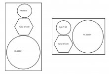
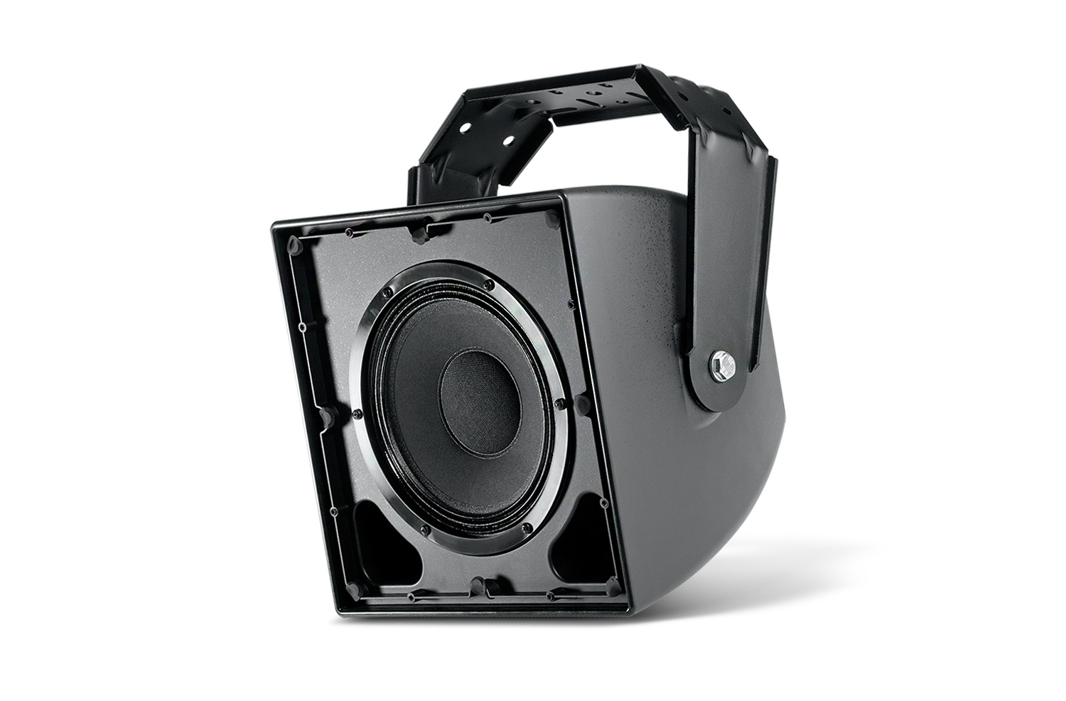
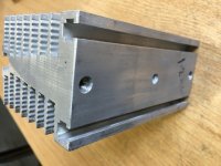
I have a 15" powered PA speaker box. It's a RCF 425-A (pretty sure it's a MK1 not a MK2). I think they were similar but maybe the MK1's had a different tweeter?)
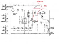
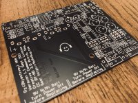
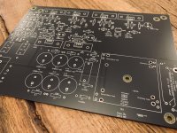
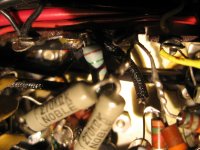
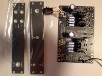
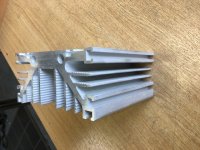
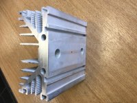
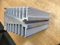
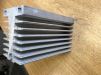
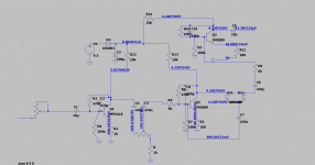
Anyway, there seems to be a very tricky problem with the amp module as I have had two pretty reputable local audio repair guys try to exactly diagnose and repair it (after lots of time trying apparently) with no luck. To replace the amp module I have been told it would be approx $650 AUS plus labour. I have been advised it is not worth the replacement amp cost and I agree ;-)
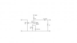
My question is, can anyone suggest a reasonably priced separate amp and components I could DIY to get this thing running again and sketch me out a wiring diagram? Looks don't matter, happy to slap some plywood to the back of it. The speaker and horn have checked out to be fine btw.
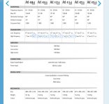
I have attached and linked anything that I thought may be of interest including a spec sheet of the MK2 (because there's not much at all on the MK1 online)
Any help would be greatly appreciated 🙂
RCF ART 425-A Active 15" 2-Way Speaker ART 425-A B&H
Newbie here!
I have a 15" powered PA speaker box. It's a RCF 425-A (pretty sure it's a MK1 not a MK2). I think they were similar but maybe the MK1's had a different tweeter?)
Anyway, there seems to be a very tricky problem with the amp module as I have had two pretty reputable local audio repair guys try to exactly diagnose and repair it (after lots of time trying apparently) with no luck. To replace the amp module I have been told it would be approx $650 AUS plus labour. I have been advised it is not worth the replacement amp cost and I agree ;-)
My question is, can anyone suggest a reasonably priced separate amp and components I could DIY to get this thing running again and sketch me out a wiring diagram? Looks don't matter, happy to slap some plywood to the back of it. The speaker and horn have checked out to be fine btw.
I have attached and linked anything that I thought may be of interest including a spec sheet of the MK2 (because there's not much at all on the MK1 online)
Any help would be greatly appreciated 🙂
RCF ART 425-A Active 15" 2-Way Speaker ART 425-A B&H


