I have been doing battle with this unit for more than 2 years. And thanks to help recieved on this forum, gotten guidance enough to have overcome it's preliminary issues. It has been resurected to some degree.
New power tubes from Jim McShane, all new electrolytic capacitors, all of the original gray capacitors and the wax coated ones are gone, replaced with new film caps.
In it's present state it works and sounds quite good with a CD player at AUX but the right channel MAG PHONO input has a problem.
It is weak. For a time, it did not work at all but I eventually discovered a bad solder connection on one of the film capacitors I installed.
This morning, I was rotating the MODE selector while listening to PHONO. It may not have any bearing on the problem but when set to MONO, both left and right sides are evenly balanced.
Set to REV, the before mentioned weak right channel switches sides but when rotating the balance control lock to lock, there is audio on both.
This is not so when in STEREO mode. The balance control performs as it should.
Apolgies if the above description is vague, it's what comes to mind.
I have swapped both 12AX7 tubes with no change so I am going to conclude that the tubes and sockets are OK.
I am obviously wrong though in my assumption that one 12AX7 is left channel and the other is right. I say that because removing either tube kills both sides.
Needless to say, there are a number of resistors associated with both tube sockets. Somewhere I got the notion those grey resistors do not necessarily deteriorate.
There has been work done to this receiver before I got it, a few electrolytic capacitors were installed. But I just now noticed a blue, presumably metal film 1.5K ohm resistor, connected to pin 8 of a 12AX7. There is no such resistor involved with the other 12AX7.
Would there be a recommendation or suggestion to start replacing resistors involved with those 12AX7 phono pre-amp tubes? Or something else?
Attachments

Best to go back the the service manual/schematic, and make the unit stock - eliminate any putzer's additions and mods.
Too many people dig into these things and add crap because they either don't know what the heck they're doing, or heard something on the internet from another putzer that they "should" do.
I'm sure kenwood knew what they were doing, far beyond some putzer's ideas.
Too many people dig into these things and add crap because they either don't know what the heck they're doing, or heard something on the internet from another putzer that they "should" do.
I'm sure kenwood knew what they were doing, far beyond some putzer's ideas.
I assume you have a schematic - email if you don't: tbavis(at)rochester(dot)rr(dot)com
Measuring four plate voltages shown on schematic should tell you where to look.
Measuring four plate voltages shown on schematic should tell you where to look.
Best to go back the the service manual/schematic, and make the unit stock - eliminate any putzer's additions and mods.
Too many people dig into these things and add crap because they either don't know what the heck they're doing, or heard something on the internet from another putzer that they "should" do.
I'm sure kenwood knew what they were doing, far beyond some putzer's ideas.
As suggested, I did look at the schematic and there is supposed to be a 1.5K ohm resistor in that position. But since what's there now is blue, it is newer than original.
And doing that drew my attention to another resistor that's different from what's on the scehmatic as far as I can tell. This one goes from pin #3 of that same 12AX7 tube to ground.
What is in place looks to be banded brown/black/brown = 100 ohms. I measured it and it's 119 ohms. The diagram claims another 1.5K ohm resistor should be there.
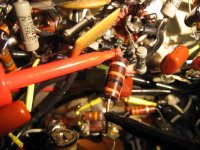
The attachment is that resistor - I estimated it as being 1/2 watt.
I assume you have a schematic - email if you don't: tbavis(at)rochester(dot)rr(dot)com
Measuring four plate voltages shown on schematic should tell you where to look.
More accurately, it would tell you where to look.
If 12AX7 plates are pins 1 & 6, the voltages I measured are not what the schematic says.
The tubes are referred to as V14 & V15. And as long as I identified them with correct orientation:
V14 pin 1 should have 65V and V15 pin 1-85V.
My measurements were V14 pin 1-82V and V15 pin 1-135V
V14 pin 6 should be 65V and V15 pin 6-85V.
My measurements were V14 pin 6-125V and V15 pin 6-135V.
Attachments
Disregarding the feedback network, on pins 3 and 8 of V14, there should be nothing but a 1.5K resistor-to-ground on those pins.
Anything else is improper, and must be corrected, period.
Putting your meter on those pins and to ground, should read 1.5K give or take a bit.
V14 is used obviously for both channels - the schematic clearly shows that (a/b).
The same goes for V15 (a/b)
And those measured voltages are way off. - troubleshoot the plate resistors down to the power supply.
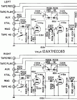
Disregarding the feedback network, on pins 3 and 8 of V14, there should be nothing but a 1.5K resistor-to-ground on those pins.
Anything else is improper, and must be corrected, period.
Putting your meter on those pins and to ground, should read 1.5K give or take a bit.
V14 is used obviously for both channels - the schematic clearly shows that (a/b).
The same goes for V15 (a/b)
And those measured voltages are way off. - troubleshoot the plate resistors down to the power supply.
I agree that the circuit components should match the schematic. I have no knowledge why a 100 ohm resistor is located where a 1.5K ohm should be.
Regarding the 4 plate resistors, those immediatly connected to the pins, two are bad - producing an OL reading. They are the gray kind (wire wound?) as it happens. The ones I thought were not susceptible to failure.
V14b pin 1 - 2W 270K ohm
V15b pin 6 - 2W 68K ohm
And how about that. V14b & V15b is right channel, the side where the problem exists.
There is a small chance I can get suitable resistors locally. If not, I guess there's no choice but an online order.
Last edited:
> V15 pin 1-135V ... pin 6-135V.
The supply is nominal 133V. V15 is not conducting. Either side! Bad heater connection? Lost cathode connection? Bad tube?
Did not see your post before I posted in response to wiseoldtech. Does it jive with your deductions?
I agree that the circuit components should match the schematic. I have no knowledge why a 100 ohm resistor is located where a 1.5K ohm should be.
Regarding the 4 plate resistors, those immediatly connected to the pins, two are bad - producing an OL reading. They are the gray kind (wire wound?) as it happens. The ones I thought were not susceptible to failure.
V14b pin 1 - 2W 270K ohm
V15b pin 6 - 2W 68K ohm
And how about that. V14b & V15b is right channel, the side where the problem exists.
There is a small chance I can get suitable resistors locally. If not, I guess there's no choice but an online order.
They are both carbon, common 1/2 watt values, check the other channel's plate resistors as well - if in tolerence (10 or 20%?).
12AX7's don't draw much current, and there's no need to go crazy with parts.
The slob that put that 100 ohm in there must have done it to increase the level, decrease feedback, or whatever.
I always say, and adhere to, "do it right or don't bother at all".
> V15 pin 1-135V ... pin 6-135V.
The supply is nominal 133V. V15 is not conducting. Either side! Bad heater connection? Lost cathode connection? Bad tube?
In those older units, tube sockets tend to get loose and sloppy.
I've just ordered six - 9pin sockets for the 1962 HK Citation 2 that's on the bench.
ALL....... all are slop by now, barely holds onto a tube!
And of course, tube testing is mandatory in any old unit.
If I remember correctly, some of those old Kenwoods used the filaments of the phono 12AX7's in the output bias circuit.
And that's the case here as well.
It serves a dual purpose - first to supply output cathode biasing, and also to provide filtered DC to the phono preamp filaments.
Fisher, Scott, many others also used a similar system.
It saves a winding on the power transformer, along with the needed extra parts, and enhances the phono section by insuring that it's nice and quiet.
The Digikey resistors arrived late last week but during the course of soldering them, another resistor broke in two. I waited until the local, small town parts/repair place reopened after a stat holiday and got lucky. They had 2.2M ohm resistors on hand which was what broke.
Replacement resistors seemed to have done the trick in that both phono channels are playing at the same volume level now.
It was a bit odd, and dismaying when I removed the two old resistors I had my eye on. Both produced a repeated OL reading on the meter but they tested within spec once removed.
I have yet to locate the various fasteners that came off this receiver before I moved last April. There is some noise at present but for now I am attributing it to an unshielded chassis and a nearby flourescent fixture. I am hoping that buttoning it up will eliminate that.
At the moment though, fairly pleased that MAG PHONO has balanced channels. At least by ear they do.
- Home
- Amplifiers
- Tubes / Valves
- ags TRIO / Kenwood KW-55A mag phono pre-amp weak channel