Hi folks, as a few of you may know from my occasional posts, one of the DIY areas I tend to focus on is design of composite amplifiers. The performance of well executed composite amplifiers tends not to be measureable as it exceeds that of high end test and measurement equipment (more on this a few pages in on the Modulus-86 thread if you're interested) and the most attractive approach in a design I'm currently working on is DC blocking caps. I wished to know if the capacitors would limit performance.
It happens I'm in Seattle on a business trip this week. So I made arrangements to visit Neurochrome Audio to get the caps assessed on Neurochrome's APx525 as part of the test services Tom offers. If you're not familiar with the APx525 it's a USD 12k or so audio analyzer which is (currently) the second best bit of audio measurement kit available---its performance is exceeded only by the APx555, which runs around USD 40k. (My current car is the best I've ever owned and I bought it new for USD 13.1k.") )
)
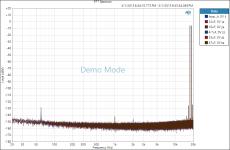
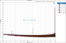
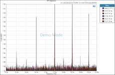
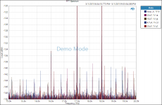
Nichicon's ES series is quite linear when there's less than about 400mV RMS developed across the capacitors. The graphs below show representative THD+N and IMD; at no point were we able to obtain results where the caps rose above the APx525's measurement limits. Below 500mV or so RMS THD+N is limited by the AP's approximately 1uV of audio band noise (20Hz-20kHz) and by the best linearity available within its range switching at larger swings---all traces including loopback on the AP group on top of each other, from 20Hz at the bottom to 7kHz at the top (loopback gets shortened to loop or loopb in the trace labels). IMD is also limited by the AP's function generator with the location of the spur frequencies shifting depending on the DC offset applied. 0 and 1V offset are shown; there's no discernable difference among the various traces as they're all identical within the limits of measurement repeatability. This held to the largest offsets tested, ±10V. Parts measured are the 6.3mm ES lineup; 4.7uF 50V, 10uF 35V, 22uF 25V, 33uF 16V, and 47uF 10V. Elna bipolars weren't measured as none of the distributors I use stocks them.
The thread title is conservative for the passband of DC blocking applications. Since the measurements don't budge when the cap under test is inserted one can infer the cap's nonlinearity is neither increasing or cancelling the AP's nonlinearities. In these charts the limit of measurement repeatability is a bit under 0.1dB on the -124dB spurs shown, corresponding to the -145dB or so noise floor (the test signal is 0dBV RMS so IMD can be read directly off the graphs). Therefore, the IMD of the caps is -145dB or better. Worst case THD is likely rather better than -130dB.
For perspective, the APx525's 1uV noise is the audio band Johnson noise of a 3k resistor. Very quiet audio op amps, such as the LME49710, have to be operated with feedback impedances of 600 ohms or less to achieve this noise floor. The -124dBV spurs are 630nV RMS, which requires a 180 ohm feedback impedance to beat---achieving similar performance in the amplifier I'm building is possible but requires either very special case optimizations or spending a few hundred euro on precision resistors. Finally, the IMD graphs are labeled Demo Mode as I put them together after the measurement session. Running AP's software without the analyzer attached requires operation in Demo Mode and I elected not erase the label in Photoshop.
It happens I'm in Seattle on a business trip this week. So I made arrangements to visit Neurochrome Audio to get the caps assessed on Neurochrome's APx525 as part of the test services Tom offers. If you're not familiar with the APx525 it's a USD 12k or so audio analyzer which is (currently) the second best bit of audio measurement kit available---its performance is exceeded only by the APx555, which runs around USD 40k. (My current car is the best I've ever owned and I bought it new for USD 13.1k.
)Nichicon's ES series is quite linear when there's less than about 400mV RMS developed across the capacitors. The graphs below show representative THD+N and IMD; at no point were we able to obtain results where the caps rose above the APx525's measurement limits. Below 500mV or so RMS THD+N is limited by the AP's approximately 1uV of audio band noise (20Hz-20kHz) and by the best linearity available within its range switching at larger swings---all traces including loopback on the AP group on top of each other, from 20Hz at the bottom to 7kHz at the top (loopback gets shortened to loop or loopb in the trace labels). IMD is also limited by the AP's function generator with the location of the spur frequencies shifting depending on the DC offset applied. 0 and 1V offset are shown; there's no discernable difference among the various traces as they're all identical within the limits of measurement repeatability. This held to the largest offsets tested, ±10V. Parts measured are the 6.3mm ES lineup; 4.7uF 50V, 10uF 35V, 22uF 25V, 33uF 16V, and 47uF 10V. Elna bipolars weren't measured as none of the distributors I use stocks them.
The thread title is conservative for the passband of DC blocking applications. Since the measurements don't budge when the cap under test is inserted one can infer the cap's nonlinearity is neither increasing or cancelling the AP's nonlinearities. In these charts the limit of measurement repeatability is a bit under 0.1dB on the -124dB spurs shown, corresponding to the -145dB or so noise floor (the test signal is 0dBV RMS so IMD can be read directly off the graphs). Therefore, the IMD of the caps is -145dB or better. Worst case THD is likely rather better than -130dB.
For perspective, the APx525's 1uV noise is the audio band Johnson noise of a 3k resistor. Very quiet audio op amps, such as the LME49710, have to be operated with feedback impedances of 600 ohms or less to achieve this noise floor. The -124dBV spurs are 630nV RMS, which requires a 180 ohm feedback impedance to beat---achieving similar performance in the amplifier I'm building is possible but requires either very special case optimizations or spending a few hundred euro on precision resistors. Finally, the IMD graphs are labeled Demo Mode as I put them together after the measurement session. Running AP's software without the analyzer attached requires operation in Demo Mode and I elected not erase the label in Photoshop.
Attachments
Last edited:
It happens I'm in Seattle on a business trip this week. So I made arrangements to visit Neurochrome Audio to get the caps assessed on Neurochrome's APx525 as part of the test services Tom offers.
Thank you for the recognition. I must admit that I was a bit surprised to see the (granted, Nichicon audio grade) electrolytic capacitors show no distortion that the AP can measure. That's pretty darn impressive. The term "sonically transparent" springs to mind.
How do you think back to back electrolytics might fare in comparison?
I suspect that depends a lot on which capacitor you choose. Seeing the measurements above, I really don't see any reason to take up the additional board area or cost of two caps in series. The Nichicon ESes measured above are not expensive caps. They run about $0.50/each @ QTY = 1 at Mouser.
However, if you'd like to get the data, I'll be happy to measure any caps you provide. I'm just a stone's throw away from you Damon, so if you have any components or amplifiers you'd like me to measure, you certainly have easy access.
I need to get a website set up for the test & measurement part of Neurochrome and work out the pricing. Stay tuned...
~Tom
Last edited:
Tom:
The crown jewel of my modest test bench is a Tektronix AA501A-based test set, plus a motley assortment of geriatric Heathkit, HP and Tek gear of various types (Boeing Surplus was very good to me). So I'm not doing too badly in that department for an amateur. But you're at least two orders of magnitude better than my setup. I've not been able yet to set up a sound card based analyzer, to give me a modest spectrum analysis capability. But the AA-501A is easy to use and has been a big help in testing amplifiers. Alas, I have no RF test gear of any sort, so I can't work on tuners very effectively and no prospect of acquiring any for the foreseeable future.
I've also had an interest in the quality of passive components, but not much ability beyond reading and researching to learn about choices and trade-offs. Back to back polar electrolytics are one of those choices but it's good to know that an affordable quality bipolar part's non-linearity is probably only a negligible source of distortion. That's been a subject of considerable debate based on subjective observations and it's good to have an objective standard.
Given that audio circuits can be designed to extremely low distortion levels, I think it's worth pursuing the small contributions that passive components make to the final sound. Too bad bulk metal foil resistors cost so much but at least low Tc metal film resistors make good cost-effective general use parts.
Danbridge of Denmark makes a component analyzer (CLT-10) that consists of a very low distortion 10 kHz power oscillator and a bandpass AC voltmeter to measure the third harmonic distortion of passive components. It can go well below -120db, depending on how it is used, possibly below -150 db.
danbridge
Wish I could make a living doing this sort of work. Closest I've come to employment in electronics in recent years has been building aircraft wiring harnesses.
--Damon
Last edited:
The best other data I'm aware of is the 2003 Capacitor Sounds series by Cyril Bateman, part 6 (10uF to 100uF) being most relevant here. For single capacitors Cyril mostly finds THDs in the range of -85 to -100dB. Third order dominant, so no cancellation in a back to back pair even if the caps come off the reel well matched for optimal voltage sharing over the pair.How do you think back to back electrolytics might fare in comparison?
I seem to also recall coming across results from roughly 2007 showing Elna RFS THDs around -124dB a few years ago but have been unable to locate them. I was hoping at best the Nichicon bipolars might match this---just enough not to limit amp performance but still a good 15dB under the floor of my measurement gear---so the results here are a pleasant upside surprise.
It makes me somewhat curious to measure selected parts from Nichicon's non-audio bipolar series. In through hole these are the EP, VP, SP, and MP (DB is bipolar as well but is for speaker crossovers and poorly suited for DC blocking, plus is NRND)---VP and EP are probably the most interesting for audio as they're not height constrained and are one package size smaller than ES. DigiKey has the VPs and Mouser all four series. In surface mount ZE, ZP, WP, and UP are all short stack as well with UN being high capacity and large footprint. UP is probably the most generally useful compromise, typically being a voltage step down from ES for the same diameter. Since the rest of the amp's all surf mount I may toss you an email on the back channel about looking at a few UP parts.I must admit that I was a bit surprised to see the (granted, Nichicon audio grade) electrolytic capacitors show no distortion that the AP can measure. That's pretty darn impressive.
Hi Guys,
Very interesting test, and something I've been looking at quite a bit lately.
I performed similar tests several years ago on an APx585 when I measured some Nichicon Polymer parts (330uF, 16V Polymer) and some back to back 100uF UCC electrolytics. My results were the same as yours... no discernible difference between having a cap present or not present in the measurement loop. I was doing it more as a sanity check at the time, so I didn't save or publish the results.
As I got reading about it again recently, I was pretty surprised to read the articles from Cyril Bateman showing generally terrible performance from everything except film caps.
I think, however, that the big differences here aren't a result of a particular brand, type, or configuration of cap(s), but more the measurement setup.
Can you guys clarify how exactly you measured in your setup? What was the source impedance? Did you use a load after the cap, or was it just the input impedance of the AP? I would assume you were measuring the cap in series configuration, not shunt?
I had the cap connected in series (as it would be in a coupling application) and used a 600R load after the cap (external to the AP) to simulate a worst case scenario amplifier input impedance. I didn't use anything to change the source impedance, so the probe came straight from the AP and into the cap.
I think the issue with Bateman's measurements is that they are effectively done in "shunt" configuration where he develops several volts AC across the cap under test. This to me is a better representation of a shunt application (supply bypassing) than a series application (AC coupling) where you aren't going to see any appreciable voltage drop across the cap if it's sized correctly. The strange part is that in shunt applications distortion is usually meaningless, and things like ESR and ESL are really what matter. The only time I see distortion being an issue is in coupling applications where the cap is generally (hopefully) subjected to a DC bias, and there is little or no AC drop across the cap itself.
Can you guys verify your test setup so I can confirm some of my suspicions?
I will be sure to repeat this test next time I have an AP in house.
Regards,
Owen
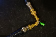
Yes, measurements are in series as DC blocking's the application (I've a jig photo to add to post 1 but haven't had a minute to download it from the camera yet). The figures are with a 20 ohm output impedance on the APx525. AP input has a 100k pulldown---very much what you'd find in a standard audio AC blocking configuration---and, other than the expected subsonic rolloff, we didn't find any difference between AC and DC coupling on the input. (Post 1 data is with AC coupling as that was running a bit quicker on some of the loopback THD+N sweeps and the AP was just left in that configuration.) Typical sanity checks were done, such as measuring a short on the cap jig versus the AP's loopback and verifying frequency response against DC coupling and higher output impedances.
20 ohm series impedance is a bit on the low side for RISO management of capacitive loads but should be pretty representative of the 25 ohms used in line drivers such as the THAT 1606 and 1646. I doubt things look much different with the common 47 ohm choice. There may be differences with some of the line driver arrangements with output impedances of several k.
Agree Cyril may be measuring different things. While the composite amp driving the cap in his jig should be quite solid it may not be representative of a more typical DC blocking arrangement. I can't obviously put a hole in it but neither can I get away from the sense the cap may behave differently depending on the effective pulldown impedance---10k versus 100k may well not matter but I could see Cyril's arrangement of essentially zero making a difference compared to 10k. More measurements would be required but Tom and I spent a lot of time getting to where we were convinced we weren't missing anything and the caps really were transparent to the AP.
Last edited:
to see cap distortion you really need (AC) Vdrop across them - working on/near the slope of either hi or low pass
I've seen distortion in Nichicon Gold audio coupling caps in a multichannel SACD player that was worse than the "lesser" grade caps used in the surround channels
measured with a Lynx Audio card - but only visible for signal frequency near or below the 3 dB low frequency corner
I've seen distortion in Nichicon Gold audio coupling caps in a multichannel SACD player that was worse than the "lesser" grade caps used in the surround channels
measured with a Lynx Audio card - but only visible for signal frequency near or below the 3 dB low frequency corner
Last edited:
I've seen distortion in Nichicon Gold audio coupling caps in a multichannel SACD player that was worse than the "lesser" grade caps used in the surround channels
There are several Nichicon series which have either a black stripe on gold sleeve, or a gold stripe on black sleeve - and they can differ quite a bit in measured tan delta.
Briefly:
FG (Fine Gold): Black on Gold, 85c
KG (Gold Tune): Black on Gold, 85c
FW: Black on Gold, 85c
KW: Gold on Black, miniaturized
SW: Black on Gold, low-profile miniaturized
KZ: Copper/Gold on Black, premium
Audio: Gold on Black, text "Audio"
Of the lot, KZ is the largest, has non-magnetic Cu leads and measures the best, while SW is the smallest, has magnetic leads and measures the worst, but YMMV. They're intended for very different kinds of applications - there are handheld/portable applications where SW will fit and nothing else will fit.
to see cap distortion you really need (AC) Vdrop across them - working on/near the slope of either hi or low pass
That's where twest and I landed last night. He took more measurements at various load and source impedances with the cap in series with the signal path. A preliminary look at the data did indeed show a THD rise as an AC voltage developed across the coupling capacitor. Some of the THD rise is due to the roll-off of the fundamental, but even when accounting for that, there was still a quantifiable difference between the series cap and a loopback measurement. I'm sure twest will post the data when he's had time to process it.
For fun, I compared the 33 uF Nichicon ES to a Solen 47 uF, 630 V polypropylene capacitor. They were line-on-line until the 33 uF hit the high-pass rolloff.
The executive summary is: If you want low THD, avoid excessive voltage across the coupling caps. This is pretty easy to do by using a relatively high input impedance, such as the 10-100 kohm commonly found in audio gear.
There are several Nichicon series which have either a black stripe on gold sleeve, or a gold stripe on black sleeve - and they can differ quite a bit in measured tan delta.
The best way to determine which cap is which is to check the manufacturer's data sheet. Usually there is enough identifying information on the cap to be able to determine the brand, series, and often date of manufacture.
The Nichicon Muze KZ are indeed nice caps! I've used some of them as bypass caps in tube circuits. Very nice...
~Tom
Last edited:
This is where I probably made a mistake in selecting the feedback capacitor in my Leach amplifiers; I used a very low voltage Black Gate 220 uF bipolars for the size and lower price, and the amplifier ran rather hot because I'd set the bias high to minimize distortion. I have to wonder that even though the actual voltage/current across the capacitor wasn't too high, it might have been outside the voltage rating on peaks. Eventually one of my amplifiers suffered a catastrophic failure and in the post mortem I found the capacitors in both channels either degraded or blown. (To say nothing of the destroyed Acoustic Research AR-11 woofer )
So I went with a Nichicon bipolar 220uF at 25 volts because it fit and was affordable. No idea if it was an audible improvement and you can't get Black Gates any more of course. I've got a couple of those Black Gates left over if someone wants to test them. It might be interesting to see if the notorious 'break-in' period is quanitifiable.
)So I went with a Nichicon bipolar 220uF at 25 volts because it fit and was affordable. No idea if it was an audible improvement and you can't get Black Gates any more of course. I've got a couple of those Black Gates left over if someone wants to test them. It might be interesting to see if the notorious 'break-in' period is quanitifiable.
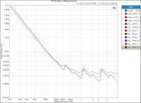
Some transition band data attached which I've been meaning to post for a while. Also, pic of the measurement jig.
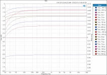
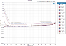
These aren't source and pulldown resistor combinations one would use since the corner frequencies are in the audio band and a fair amount of voltage is developed across the DC blocking caps. But the data is still kind of interesting. Note highpass filters accentuate THD+N slopes in their transition and stop bands. If the fundamental is attenuated but the harmonics are not then the THD increases as (fundamental attenuation) * (number of significant harmonics) from filter rolling off the fundamental even though there's no actual increase in the size of the distortion products. In the stop band THD goes as sum_over_harmonics(harmonic + 6dB * log2(harmonic order)) for a first order filter. E.g., 9dB boost if the third harmonic is dominant.
It's also straightforward to throw together a spreadsheet for the pull down resistor size required to keep the voltage across the DC block caps below some value at some frequency limit. Example attached. The common choice of a 100k pulldown isn't a bad one for electrolytics, though some attention to the input impedances of the op amp or diff pair beyond is warranted.
Attachments
snip ...
For fun, I compared the 33 uF Nichicon ES to a Solen 47 uF, 630 V polypropylene capacitor. They were line-on-line until the 33 uF hit the high-pass rolloff.
...
~Tom
Hello Tom,
I am liking the looks of the current generation Audio Precision APx analyzers.
For fun have you tested any Paper In Oil capacitors?
DT
Hello,
Then if I use a nichicon ES capacitor as input capacitor of a single rail amplifier, the cap will see Vcc/2 (my case : 12VDC) across terminal as DC voltage and the audio signal (1Vrms). I understand but it's not clear for me: it is best to use high voltage ES capacitor (ex 50V) rather than low voltage (ex 25V) in order to achieve low noise and thd or there is no relation about thd, noise and value of dc voltage across cap versus cap voltage rating ?
Then if I use a nichicon ES capacitor as input capacitor of a single rail amplifier, the cap will see Vcc/2 (my case : 12VDC) across terminal as DC voltage and the audio signal (1Vrms). I understand but it's not clear for me: it is best to use high voltage ES capacitor (ex 50V) rather than low voltage (ex 25V) in order to achieve low noise and thd or there is no relation about thd, noise and value of dc voltage across cap versus cap voltage rating ?
I'd have a question about an aspect i didn't see mentioned so far, if anyone measured this aspect and is willing to share his experience:
The best audio sounding gear i heard that used nichicon muse in the signal path used NICHICON muse bipolar when there was 0v DC across the cap(op-amp output) and regular Unipolar Muse (like today's nichicon KZ) when there was any DC voltage between stages from 0.5v..to 10v.
Is there a reason to avoid bipolars when you have a DC potential between stages you need to couple?
There is no strong relation between noise and voltage rating, at least with 25 V and 50 v rated voltage.or there is no relation about thd, noise and value of dc voltage across cap versus cap voltage rating ?
I have seen that 50 V rated caps usually a bit better than 25 V rated (and lower). It is as usual for almost any electrolyte type.
The noise has a strong relation with a capacity - the larger the capacity the lower the impedance and so the lower is the introduced noise and distortion.
I'd have a question about an aspect i didn't see mentioned so far, if anyone measured this aspect and is willing to share his experience:
The best audio sounding gear i heard that used nichicon muse in the signal path used NICHICON muse bipolar when there was 0v DC across the cap(op-amp output) and regular Unipolar Muse (like today's nichicon KZ) when there was any DC voltage between stages from 0.5v..to 10v.
Is there a reason to avoid bipolars when you have a DC potential between stages you need to couple?
Do I hear anyone...?
 . u pick what you like and what u can afford.
- Home
- Design & Build
- Parts
- Nichicon Muse ES bipolar caps measured: <-120dB THD, <-140dB IMD