Hi All,
In my old DAC there are 2 PMI OP-44 opamps, next to one of them there is a blown 4.7uf tantalum capacitor that is directly connected to pin 3 (IN+) of the opamp therefore I would like to replace the opamps while I’m replacing the tantalum capacitors, does anybody knows which opamp can replace the op-44 opamps?
Thanks
The DAC is Orelle DA-180, I can’t find schematics for it, I’ll appreciate if someone has it and can upload it.
There is no reason to suspect the opamp will be anything other than 100% good tbh. The cap failing won't damage the opamp.
The OP44 is an old device but it was very highly specified for the time. I wouldn't like to suggest any alternative without knowing a lot more and also having the means to test whether any replacement works correctly.
If the offset null pins are in use then that is a further complication.
The OP44 is an old device but it was very highly specified for the time. I wouldn't like to suggest any alternative without knowing a lot more and also having the means to test whether any replacement works correctly.
If the offset null pins are in use then that is a further complication.
Thanks.
Can the tantalum capacitors can be replaced with aluminium electrolytic capacitor like Os con or such?
Can the tantalum capacitors can be replaced with aluminium electrolytic capacitor like Os con or such?
If the offset null pins are in use then that is a further complication.
It seems that pins 1 and 5 (null) are not connected anywhere.
Hi All,
In my old DAC there are 2 PMI OP-44 opamps, next to one of them there is a blown 4.7uf tantalum capacitor that is directly connected to pin 3 (IN+) of the opamp therefore I would like to replace the opamps while I’m replacing the tantalum capacitors, does anybody knows which opamp can replace the op-44 opamps?
Thanks
John Larkin of Highland Technologies recommends derating tantalum caps to run at no more than 1/3 of the rated
Voltage. Having had the occasional tantalum failure (always catastrophic) I think that is good advice. IOW if its
a 12V bus use a 35V cap.
As for the opamp, unless it failed I would leave it. It's 100V/u sec slew and 15MHz GBW and sufficiently quiet.
Whatever you put in will be different but not likely better. Just because you might be able to measure it, can
you hear it?
G²
Thanks.
Can the tantalum capacitors can be replaced with aluminium electrolytic capacitor like Os con or such?
I would think so. If the cap has physically 'blown' then it sounds like it is across a rail that can deliver heavy current.
One problem with traditional tants is that they are apparently susceptible to very fast rise times of any applied voltage which of course includes transients. I understand it is that scenario that often causes them to fail.
You have to be practical and realistic though and consider there are zillions of these things out there and that if you replace it with a modern equivalent it will almost certainly never fail again.
>" they are apparently susceptible to very fast rise times of any applied voltage"
So it's because they're such a "good" capacitor that they end up taking a huge slug of current in response and then structurally, they cant take it - so they blow up.
If these were in the audio path somehow, I'd replace them with better than Al-Els.
So it's because they're such a "good" capacitor that they end up taking a huge slug of current in response and then structurally, they cant take it - so they blow up.
If these were in the audio path somehow, I'd replace them with better than Al-Els.
Use tantale in audio path was never a good idea. Others regular use : as local filter for half voltage supply for opamp or for active drift correction... Something else with cap ? a voltage divider ?
You have to be practical and realistic though and consider there are zillions of these things out there and that if you replace it with a modern equivalent it will almost certainly never fail again.
You make it sounds like replacing tants with modern equivalent it’s a bad thing to do 😛
The tants are 4.7uf 35V, What is the benefit of using tantalum capacitors over aluminum electrolytics of the same size and value?
Thanks
What case type is this tantal and what place in the circuit does it take (what it does?)?
It may be even possible to change it to something like SMD ceramics 1210 4.7 uF 50 V X7R (large size x7r ceramics is quite good for not the straight signal path).
It may be even possible to change it to something like SMD ceramics 1210 4.7 uF 50 V X7R (large size x7r ceramics is quite good for not the straight signal path).
Last edited:
You make it sounds like replacing tants with modern equivalent it’s a bad thing to do 😛
The tants are 4.7uf 35V, What is the benefit of using tantalum capacitors over aluminum electrolytics of the same size and value?
Thanks
How so? 🙂
I'm saying if you fit a modern tant it will never fail again (that cap).
Tants have a very low ESR over a wide frequency range and were considered superior for decoupling applications where HF noise had to be filtered out.
Without detailed examination of the caps actual function in the circuit it is impossible to say whether tantalum really is the best choice today or not.
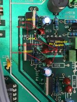
As far as I can see there are 3 tants on every op-44, 2 of them are directly connected to LM317 and LM337 regulators and the 3rd is connected to the op-44 pin 3 input.
We would really need the circuit drawing out to see how the cap connected to pin 3 is configured. Pin 3 might go to ground if the opamp is configured as a virtual earth stage or I/V convertor.
Unfortunately I can’t find schematics for it but I can tell you that pin 3 is indeed connected directly to the ground.
Try to follow pcb in order to retrace others parts connected to cap.the 3rd is connected to the op-44 pin 3 input.
Unfortunately I can’t find schematics for it but I can tell you that pin 3 is indeed connected directly to the ground.
So that reinforces my view that the chip will almost certainly be just fine... fit whatever you have to hand and give it all a listen. I'll bet you won't notice anything different at all.
One point though is that if the cap failed short it will have probably pushed the regulator into thermal limiting. It would be wise to check that section of the circuit over and also look at the unregulated input to the regulator. Make sure no small series resistors have suffered with any overload.
- Home
- Design & Build
- Parts
- PMI OP-44 opamp replacement