Extending the AEM6000 design to ppm THD
- By suzyj
- Solid State
- 84 Replies
I've built a number of amps over the years based on David Tilbrook's AEM6000. They've all been really good, reliable, low distortion, quiet amps. With the newer ones I've started departing a little from David's topology, initially by dispensing with one side of the VAS, which I built as a set of 50W modules that work very nicely, and now by realising that by dispensing with one side of the VAS, I can use current-mirror loads for the preceding stage, increasing the load impedance for that stage significantly and allowing for significantly better distortion performance.
I started discussing this in this thread http://www.diyaudio.com/forums/solid-state/288479-aem-6000-ready-build.html. Chalky pointed out that my VAS current wasn't well defined, being set from one side of a current mirror, so I've been working since then to get a handle on how to stabilise the VAS current without throwing away the gain. This initially involved using current sources and sinks tied back to the previous stage's tails, and more recently using a resistor across the mirror to define the collector voltage on the mirrored side at the cost of some gain.
While at it I changed out some of the VAS and preceding stage transistors, using the KSA1381/KSC3503 for the VAS, and IMX8/IMT4 duals for the preceding stages. Tail currents are provided by the cheap and cheerful MJE340/350.
I think I've reached a reasonable compromise with this, and I'm working now on layouts.
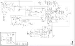
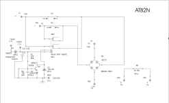
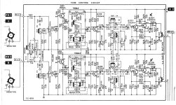
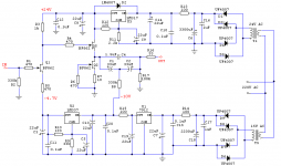
Here's the simulation schematic:

My goal with this is 1ppm THD at 1KHz/50W/8R, without huge supplies. I've set a somewhat arbitrary limit of 100mA bias for the LatFETs.
I've achieved this and then some. With gain set to 20dB, THD at 1KHz simulates at 0.4ppm, at 10KHz I achieve 3.5ppm, and even at 100KHz THD is a manageable 0.04%.
So, an explanation of how things work. The first stage is a completely conventional matched JFET (SST404), with cascode provided by an IMX8 dual and resistor loads. Tail current is set to 5mA, of which 3.5mA is used to bias the cascode and the rest flows through the JFETs.
The second stage is where I depart a little from David's topology. It's a symmetrical differential pair. Rather than the resistor loads of the AEM6000, I use a pair of current mirrors. Tail current for the differential pairs is set to a healthy 9mA. Dissipation is low enough that I can continue to use the IMX8/IMT4 duals both for the differential pairs and the current mirror loads, which is nice, as I really need a good match here, not to mention that these little things are lovely and fast, with plenty of gain at just the right current. I just use MJE340/350s for the tails as I don't need speed here but do need some dissipation.
Note R30 & R31. These 47K resistors waste some gain in this stage to ensure the collector voltages of Q17 & Q18 reasonably closely follow their mirrors. This allows us to define the VAS current by noting that the collector voltage here is defined by one Vbe + the current flowing through R18-22.
The current in the VAS is set by two mechanisms. The first is that for the VAS transistors (KSA1381/KSC3503 - Q14 & Q15). This is set by their emitter resistors. They have constant current loads (Q19 & Q20), whose currents are set by their emitter resistors, recycling the reference from the preceding stage tails.
The loads must be set at a lower current than the VAS transistors, to ensure current flows through R28, and hence the bias for the final stage drivers is set. I chucked a diode in here (thanks PB2), because if the VAS transistors and loads aren't biased correctly there was otherwise nothing to stop current from flowing the wrong way through R28.
I run the VAS transistors at 10mA, and the loads at a tad over 7mA, leaving the balance of a little over 2mA flowing through R28. This is then tweaked to give me 100mA driver bias.
Compensation is straightforward. A couple of caps across the VAS transistors, some RC across the first stage diffamp, and normal phase-lead compensation at the feedback point. I can push the gain all the way down to 3 (1ppm at 10KHz!) without it taking off, so I'm confident that it can be reasonably easily stabilised at more usual voltage gain levels.
Anyway, I think it's cool. I'm gonna build a couple, and I'd appreciate critique, especially of my logic around the VAS current stabilisation mechanism, as this is the area where I'm least confident.
I started discussing this in this thread http://www.diyaudio.com/forums/solid-state/288479-aem-6000-ready-build.html. Chalky pointed out that my VAS current wasn't well defined, being set from one side of a current mirror, so I've been working since then to get a handle on how to stabilise the VAS current without throwing away the gain. This initially involved using current sources and sinks tied back to the previous stage's tails, and more recently using a resistor across the mirror to define the collector voltage on the mirrored side at the cost of some gain.
While at it I changed out some of the VAS and preceding stage transistors, using the KSA1381/KSC3503 for the VAS, and IMX8/IMT4 duals for the preceding stages. Tail currents are provided by the cheap and cheerful MJE340/350.
I think I've reached a reasonable compromise with this, and I'm working now on layouts.
Here's the simulation schematic:
My goal with this is 1ppm THD at 1KHz/50W/8R, without huge supplies. I've set a somewhat arbitrary limit of 100mA bias for the LatFETs.
I've achieved this and then some. With gain set to 20dB, THD at 1KHz simulates at 0.4ppm, at 10KHz I achieve 3.5ppm, and even at 100KHz THD is a manageable 0.04%.
So, an explanation of how things work. The first stage is a completely conventional matched JFET (SST404), with cascode provided by an IMX8 dual and resistor loads. Tail current is set to 5mA, of which 3.5mA is used to bias the cascode and the rest flows through the JFETs.
The second stage is where I depart a little from David's topology. It's a symmetrical differential pair. Rather than the resistor loads of the AEM6000, I use a pair of current mirrors. Tail current for the differential pairs is set to a healthy 9mA. Dissipation is low enough that I can continue to use the IMX8/IMT4 duals both for the differential pairs and the current mirror loads, which is nice, as I really need a good match here, not to mention that these little things are lovely and fast, with plenty of gain at just the right current. I just use MJE340/350s for the tails as I don't need speed here but do need some dissipation.
Note R30 & R31. These 47K resistors waste some gain in this stage to ensure the collector voltages of Q17 & Q18 reasonably closely follow their mirrors. This allows us to define the VAS current by noting that the collector voltage here is defined by one Vbe + the current flowing through R18-22.
The current in the VAS is set by two mechanisms. The first is that for the VAS transistors (KSA1381/KSC3503 - Q14 & Q15). This is set by their emitter resistors. They have constant current loads (Q19 & Q20), whose currents are set by their emitter resistors, recycling the reference from the preceding stage tails.
The loads must be set at a lower current than the VAS transistors, to ensure current flows through R28, and hence the bias for the final stage drivers is set. I chucked a diode in here (thanks PB2), because if the VAS transistors and loads aren't biased correctly there was otherwise nothing to stop current from flowing the wrong way through R28.
I run the VAS transistors at 10mA, and the loads at a tad over 7mA, leaving the balance of a little over 2mA flowing through R28. This is then tweaked to give me 100mA driver bias.
Compensation is straightforward. A couple of caps across the VAS transistors, some RC across the first stage diffamp, and normal phase-lead compensation at the feedback point. I can push the gain all the way down to 3 (1ppm at 10KHz!) without it taking off, so I'm confident that it can be reasonably easily stabilised at more usual voltage gain levels.
Anyway, I think it's cool. I'm gonna build a couple, and I'd appreciate critique, especially of my logic around the VAS current stabilisation mechanism, as this is the area where I'm least confident.


