Holey Basket Coral FE103As and Tamradio SE OPTs
Hi All,
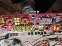
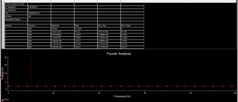
Most should know what this stuff from the Sony TC500/TC500a R2R is. I picked one up to cannibalize the power supply.
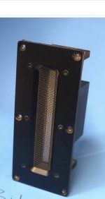
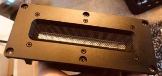
The surrounds on the Coral FE103A variants feel pretty good--not too stiff. See minor damage to one dustcap. I don't think that'll make a difference. These are nicer than my personal set, but I'm too lazy to swap them out.
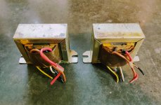
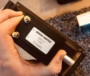
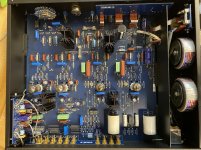
The Tamradio/Tamura-ish transformers look fine too. These used 6AQ5 outputs and are great for EL84 or 6V6 SE projects like the RH84. Interesting possibilities with the recording head tap.
$75 for the speakers, $50 for the OPTs. $15 to ship to CONUS for either the speakers or OPTS. Free shipping to CONUS if you want it all. Others ask for quotes.
Paul
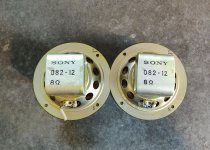
Most should know what this stuff from the Sony TC500/TC500a R2R is. I picked one up to cannibalize the power supply.
The surrounds on the Coral FE103A variants feel pretty good--not too stiff. See minor damage to one dustcap. I don't think that'll make a difference. These are nicer than my personal set, but I'm too lazy to swap them out.
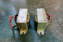
The Tamradio/Tamura-ish transformers look fine too. These used 6AQ5 outputs and are great for EL84 or 6V6 SE projects like the RH84. Interesting possibilities with the recording head tap.
$75 for the speakers, $50 for the OPTs. $15 to ship to CONUS for either the speakers or OPTS. Free shipping to CONUS if you want it all. Others ask for quotes.
Paul


![20200814_155336[1].jpg](/community/data/attachments/786/786619-262ebff96970f3ea6f85f9f9dc3296ec.jpg?hash=Ji6_-Wlw8-)