Intrinsic instability in a negative Jung style regulator?

Greetings gentlemen😱

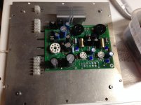
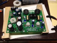
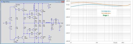
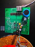
For the past month I have been working on a super regualtor project with Jung style topology, but also includes some trick from the golden reference regulator -> Buffered error amp output to the base of pass element.

The error amp is good old ne5534, voltage reference being the Jung Led reference, and for the pass elements Im using NJT4031/4030 pair...

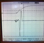
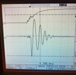
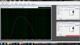
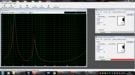
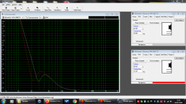
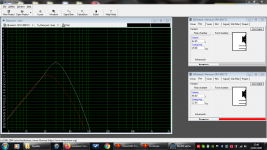
So here is basically what happened while debugging the whole assembly. The positive supply was rather successful, no magic smoke. But something rather strange happend to the negative regulator, when testing with a 200mA step, the output rings pretty badly on the oscilloscope. The ringing stops after 5-6 periods.

In the contrary, the positive reg shows a very ideal response without ringing. Voltage just goes down, negative feedback kicks in, overshoot a little, then voltage returns to the set value. Nothing more.

To tackle this ugly ringing, a few methods was tried, including: Switching pass element to slower bjt, adding input decouple cap, adding output decouple cap(aluminum, of course), increasing local feedback around erroramp. But none of these solves the problem completely, amplitude gets lower and stills rings for a while.

Anyone familiar with this issue? Thanks in advance..

---------------------------------------- Update----
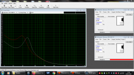
One interesting result: When using the faster driver BJT 2SA2039, the ringing was like 4 time larger in amplitude and lasts longer. When switched to MJE350 the ringing was almost stopped. Reminds me of Mr. Didden once mentioned about the error amp and pass element selection: They shall have different speed so that phase shift wont happen at the same frequency.

Attachments

  • IMG_20200723_150133.jpg
    IMG_20200723_150133.jpg
    721.5 KB · Views: 246
  • IMG_20200723_150103.jpg
    IMG_20200723_150103.jpg
    640.7 KB · Views: 248
  • IMG_20200624_204845.jpg
    IMG_20200624_204845.jpg
    577.9 KB · Views: 255

Why high current makes rectifier arc?

Hi everyone.

As far as I know, arcing is caused by a high current through the rectifier tube, which leads to a high anode-cathode voltage drop.

If this is so, will arcing happend if using a 250 Vrms secondary? Even if the full voltage is across the tube, would (in theory) 250 Vrms (352 V-pk) be enough to make a rectifier arc? Let's take a GZ34, compare to its PIV of 1700 V, those 352 V seem nothing to worry about.

Maybe there're other reasons for arcing appart from high anode-cathode potential, like insufficient emission.


Or maybe I'm confusing apples and oranges 🙂

I appreciate any observation on the matter. Thanks!

Retrofit Project for Intercom

I am new to this forum and hoping to find some guidance on where to start on a project I have been planning to do. I have no technical knowledge around speakers and their design but have an engineering background and can work my way around some electronics. Was hoping here might be a good starting point.

I have a 70's intercom / radio built into the wall of my kitchen / dining area which I would like to modernize to play music at higher quality as now it has lots of static and generally low quality. Not looking for a super HiFi system, but I would like it to be good not like just some alexa/google home speaker quality. I would like to keep the aesthetic of the device and all exterior features of the unit, but gut out the internals as the inside looks like a circuits lab, project bread board. It would be a plus for the knobs to be functional to some capacity as well. The unit measures at about 17 x 9 inches, and play into an area about 15 x 15 ft wide. I have added some images for reference of the unit on the wall.

Attachments

  • 84bbd294-282d-4b9a-b21d-e06c8cf487ad.jpg
    84bbd294-282d-4b9a-b21d-e06c8cf487ad.jpg
    42.4 KB · Views: 161
  • d8cff2bf-02a8-4028-b7bf-f944fbe2b03c.jpg
    d8cff2bf-02a8-4028-b7bf-f944fbe2b03c.jpg
    189.5 KB · Views: 166

6s41s

6c41s

Hi all,

The output tube is 6c41s, and I would like to drive it into class A2.

Not too keen on the DC coupled cathode follower, mainly because it requires a separate negative supply. Loftin White topology has been said to sound very good, so Im keen in that direction.

The 'normal' operating point of the 6c41s is 180v/60v/120mA. It is driven by 'improved' SRPP stage with 5965, it should provide gain of 40+, which should provide plenty of drive to the output stage..

Since this is my first attempt at this kind of design, hoping to get it checked first. :redhot::redhot::redhot:

btw- I'm aware of the dangers of Loftin White, but I have been building amps for many years now so its a risk i'm keeping in mind. Thanks in advance.

Attachments

  • loftin white 6c41.jpg
    loftin white 6c41.jpg
    71.4 KB · Views: 866

TEAC as-100 preamp not working.

Hi all
I was wondering if someone could advise me on where to look for a problem with my TEAC. Its a integrated amp built around 1971. Is very well built and was working fine when I bought it about 10 years ago. About five years ago the preamp stopped working. Amplifier works fine and I can plug in a source direct to the amp and everything works as it should.
Both channels arent working on the preamp, no sound nothing.
Checked the power to the control amp board and seems fine.
All the caps look good. Checked all the wiring and circuit boards with the multi meter continuity buzzer and cant find anything.
Checked the soldered joints all look good, redone a few just in case.
Checked all the switches.
Everything looks clean and unmolested.
Probably something simple I have missed, weird its both channels.
Here is the service manual if anyone cared to help. Thanks.

https://www.google.com/url?sa=t&rct...e-Manual.pdf&usg=AOvVaw3_Be8aP0T0tBJ4Pn0_BZFQ

Detective work to trace fault: Looking for Densen DM30 power amp schematic

Hi all,

Have a Densen DM-30 in to be repaired and my repair tech is looking for the service manual/ schematic to help trace the fault.Anyone out there in DiyAudio land have such a thing?
🙂

He’s had a inspection and he reports that “both output relays aren’t engaging.“
To help, any idea Guys as to what area the fault may lie in?

Recent repair work was done by amps previous user, wonder if it’s in the same ballpark?
From his Technicians repair paperwork...(and I quote...)

“Diagnostic indicated high offset (DC) in output with several components burned, in the output circuit. Failure found in IC that supervises Protection; it was short circuited and burned adjacent components.
All parts removed and changed, offset set and bias done in both channels. Stress test and all showed fine.


So if both Output relays on Amp aren’t engaging....possible connection to what was at fault before?
Are output relays connected to protection circuit in the Densen?

Thanks very much.
Just bought the Amp and it arrived DOA on right channel - after a 4 week wait on delivery...so quite frustrating!

Amp suggestion

I'm building a set of high efficiency line source speakers (98db/w) and looking for suggestions for a high quality amplifier design with balanced inputs. I want to build monoblocks that will be located near each speaker which necessitates long interconnects. The speakers are a nominal 8 ohm load.

I'm actually almost done with a pair of F5T monoblocks (two output pair, no diodes, cascoded, 28v rails), but I'm using Jensen transformers for balanced inputs. I started building these before I decided to build the more efficient speakers, so now I'm wondering whether there might be a better option.

I have active servo-controlled open baffle stereo subs which will handle up to 80hz or so, so the amp doesn't have to "plumb the depths". With this kind of efficiency (and a line source), I don't think I need more than single digit watts.

Suggestions for a low-power, balanced-input, super-high-quality SS amp design? I'm obviously going to finish the F5T (should be able to power up one channel this weekend), but always thinking about the next project or modification.

Repair Onkyo SR508

My mom dropped off her SR508 for me to repair. Found shorted output transistors on the back left. Wonderful person in this thread Replacements for SA1941 and SC5198 helped me out with some replacement output transistors. Got those replaced. Also replaced open emitter resistor on those output transistors.

Then found fuses to amp board were blown. Replaced those.

Unit now shuts down after power up. Found the emitter resistor on one of the drivers was blown (open, should be 100R). Replaced that (temporary currently since these amps SUCK to get the main board out of.

Unit is still shutting down for some overload. Thermal camera shows the output transistors and emitter resistor for them getting hot. But they seem fine (no shorts I can find). Driver transistors seem fine as well.

I don't get where else to look. Unit powers up for maybe half a second (I can see a voltage across the P6085 plug, but it doesn't seem to respond much to turning the trim pot. hovers right around 4.6V. Which is obviously super high since it should be down around 2.5mV. So either something is shorted, (one of the output transistors even though they seem fine), or something is driving the outputs fully on.

Any thoughts? On the plus side, at least the board is well labeled.

Attachments

  • SDL Output.jpg
    SDL Output.jpg
    139.6 KB · Views: 257

DIY SKA Audio GB150 mosfet pwer amp kit

Any interest/offers for parts or repair?

SKA Audio GB150 (2x150w) mosfet power amp kit built by Greg Ball. One channel working fine, other channel working but distorting. Useful for power supply and chassis at least.

View/Pick up Wellington New Zealand, or could possibly ship within NZ but not offshore.

Attachments

  • Amp_GB150.jpeg
    Amp_GB150.jpeg
    848.7 KB · Views: 344
  • SKA_GB150 Schematic.jpg
    SKA_GB150 Schematic.jpg
    192.7 KB · Views: 415

Highest crossover frequency for H frame?

Hi guys, I thought I would pick your big brains before I go off researching this all day, and not do any of my work again lol.

May someone please tell me how high I can go crossing over a 15" Faital Pro 15400 in a compact H frame minimally constructed to the dimensions of the woofer? The woofer being inset centered back about 6 inches into the H frame. I know my 15400's play nicely in the upper bass frequency's, but I don't know how it would affect off axis response there being inset and all.

These would be actively crossed/EQ'd 3 way and mated MTM OB with Heil AMT 1 and Faital pro 10" 10FE200's. Also I was thinking for the Tweeter my Tymphany DFM-2535R00-08 and Dayton H812 as I love that combo! I don't know what would be better.

Thanks for your thoughts!

About a phono preamp and decompensated op amp

Hello

Since the gain of this preamp (like any phono preamps) go down to 0 db over 100 khz, and most decompensated op amp are stable in gains equal to or greater than five. In the phono preamp like the one in the image, does using a OPA637 or any decompensated op amp can made the circuit oscillate at arround 100 khz ?

Thank

Bye

Gaetan

Attachments

  • phono preamp-walt jung circuit big.GIF
    phono preamp-walt jung circuit big.GIF
    40.4 KB · Views: 404

Subwoofer issues

Hello everybody

Last weekend I've finished my subwoofer.
Everything is pretty good - nice, clear and tide bass up to 40Hz.

Below that point I got huge boost, at least 10Db or maybe more around 30Hz.coming out from the ports - all the furniture into the room and windows start shaking

I've moved the box around the room. but nothing changed.
I've tried damping the ports with polyfill, but that has very minimal effect.


Driver Parameters
12'' carbon cone

DVC 8ohm in parallel 2x150W

Fs 18Hz
Vas 225l
Qts 0.19
Xmax 5.4mm
Sd 495cm^2


Enclosure
ported
Vd 62l
F3 29Hz
dual port effective diameter 100mm
length 37.5cm
1'' polyfill applied on the sides, top and bottom

Plate amplifier BK BSBP 275W/4ohm

IMO the enclosure size is OK, even is slightly bigger than manufacturer's recommendation of >50l , but the tuning frequency seems to be too high.

I intend to go to a ports extension, making them twice longer about 75- 80cm
I've played with WINlSD last night and I made a comparison between the two different setups.

Would you explain to me what the ''Port Gain'' diagram means, please? Why gain of -6Db makes such a big output?

Any suggestions?

Attachments

  • Monacor SPH 300CTC Transfer Function.PNG
    Monacor SPH 300CTC Transfer Function.PNG
    177.1 KB · Views: 189
  • Monacor SPH 300CTC Impedance.PNG
    Monacor SPH 300CTC Impedance.PNG
    179.5 KB · Views: 198
  • Monacor SPH 300CTC Group Delay.PNG
    Monacor SPH 300CTC Group Delay.PNG
    175.7 KB · Views: 195
  • Monacor SPH 300CTC Cone Excursion.PNG
    Monacor SPH 300CTC Cone Excursion.PNG
    176.8 KB · Views: 195
  • Monacor SPH 300CTC Port Gain.PNG
    Monacor SPH 300CTC Port Gain.PNG
    176 KB · Views: 191
  • home audio.jpg
    home audio.jpg
    351.7 KB · Views: 114

Need help with a ES9038Q2M DAC

Hello,

I bought a ES9038Q2M dac from audiophonics for a complete dac + amp + speaker project. First i bought a ES9038Q2M with a screen and pot to adjust the volume and select the source, but as it was out of stock i had to go with this dac instead :

ESS ES9038Q2M DAC Module I2S Optical Coaxial 32bit 384khz DSD256 - Audiophonics

As often with chinese thing like that, audiophonics just resell it and the technical information are seriously lacking. Over the years i have several talk with the guy from audiophonics technical service, and i must i really don't like him. He obviously doesn't know anything about the stuff they sell and he doesn't want to look very hard...

So when i ask them what kind of pot i should use to adjust the volume and how the source is selected, they answer any pot will do and that the dac will automatically lock to the signal it detects.

Of course it is not the case. 😡

I tried with a standard Lin pot and it doesn't adjust the volume between 0 and 100%, more between 50-70% to 100%.

And for the source selection, only the mode button on the board can select the source.
Automatic selection looked coherent because i don't see people to open the case to press the mode button every time they want to change the source 😱
But apparently the chinese didn't think that way 🙁

From what i understand the dac is control by a N76E003AT20 ic from Nuvoton. There is the mode and vol + and - button, plus a connector for a pot (3v3 VOL GRD). There is also a space for a 5 pin connector on the top of the ic, but as there is no documentation i don't know what it is doing, maybe a way to connect an external source switch 😕

So as audiophonics doesn't want to answer me about this, i hoped someone here would be kind enough to advice me how to make this thing to work properly 🙂

Help! on Bunggard Fotopositive PCB

Guys
it's ridicoulous that after 40 years of manufacturing PCB's I don't get the point what is going wrong with my manufacturing PCB..
I use Bunggard 35um PCB. Fotopositive.
Later days I use Tracing paper as Film as well as Laser Film. Both were working good. but lately problems occured I never thought of it..

I get bad results when etching the PCB with Ferro Chlorid 3.
Instead of edging the exposed sequences of the PCB it eats up the Laqeur of the portion which should be the tracks,,

I ordered about 20 Plates PCB with size of 10cm * 16cm. The half of it I had to throw away because at edging all of them were useless..
I use the same Printer, The same Glasses, the same Ultraviolet lamps, exactly the correct exposure timing. and and and and
I always use new devloper, same Edging solution measured by weight. mixed by weight to a 10th of a gramm exact.
And still got to many failures..
and it doesn't matter if I use Film or Tracing Paper.. Finally I think that I got old PCB material from that Store I buy these.
I always measure developer Temp very exaclty 20degrees Celsious.

14 Days ago I again got failing PCB,s so I changend the Edging ACID to Natriumpersulfat. I almost died because the Air vent Failed and to this day I'm feeling sick, lost my short time memory to a big degree, sometims walking around like drunk. and if I sit down or lay down everything is turning like o a carusel. And I do not drink or smoke nor smoinkg pot.. nor taking drugs.. just 5 minutes of this poisoned air of this NATRIUMPERSULFAT almost make me to a usless Person.

And I can't take off from work, because there is nobody to do my work.. But this aint a problem.. but the bad PCB's is a big problem I can not finish my testing with such boards.

Show you a good one and the ones with very strange structure..
What makes it more strange, it kill the BIG TRACKS not the small ones.. LOL
Check out the pics please..

May some of you have seen something like that before..
Let me know if you think you know the reason..

Thanks MANY Thanks..
Regards Chris Hess

Attachments

  • 1. PCBs.jpg
    1. PCBs.jpg
    188.9 KB · Views: 242
  • 2. good pcb.jpg
    2. good pcb.jpg
    158.6 KB · Views: 239
  • 3.Good small letters OK - Thick lines OK.jpg
    3.Good small letters OK - Thick lines OK.jpg
    151.7 KB · Views: 251
  • 4.Bad PCB yesterday.jpg
    4.Bad PCB yesterday.jpg
    340.6 KB · Views: 191
  • 5. Bad Edging - Swollen up lines..jpg
    5. Bad Edging - Swollen up lines..jpg
    218.7 KB · Views: 231
  • 6. lines ugly.jpg
    6. lines ugly.jpg
    178.3 KB · Views: 110
  • 7. Small letters OK thick line bad.jpg
    7. Small letters OK thick line bad.jpg
    162.1 KB · Views: 92

FS: Raal 140-15D AM Ribbon Tweeters (Qty 3)

SOLD: Raal 140-15D AM Ribbon Tweeters (Qty 3)

For Sale: Raal 140-15D Ribbon Tweeter with Amorphous Core. Quantity 3, two used probably less than 50 hours. One still new in box. These have been in storage for several years. I built some prototype speakers, then before I could build the final cabinets I put them away while I remodeled my house. I never did get back to this speaker project. Asking $750 for all three. $650 for a two. Shipping and paypal fees extra. US shipping only. Local pickup in SF Bay area possible.

Attachments

  • 20200723_185508.jpg
    20200723_185508.jpg
    857.6 KB · Views: 342
  • 20200723_185526.jpg
    20200723_185526.jpg
    824.4 KB · Views: 290
  • 20200723_185605.jpg
    20200723_185605.jpg
    844.4 KB · Views: 322
  • 20200723_185817.jpg
    20200723_185817.jpg
    973.8 KB · Views: 283
  • 20200723_185835.jpg
    20200723_185835.jpg
    855.1 KB · Views: 266
  • 20200723_190530.jpg
    20200723_190530.jpg
    715.7 KB · Views: 123

Troubleshooting TU-8200R headphone jack

Greetings all;

I've just finished the TU-8200R and the TU-8500. Both units fired up right away, and sound great! Yay!

I do have a minor issue with the TU-8200R's headphone jack, though.
When I plug in the headphones, one of the speaker channels doesn't mute. The other speaker channel does. The audio in the headphones is correct and OK.

Any guidance on how I might troubleshoot this is appreciated. I suspect a solder bridge, but I'd rather not tear down the amp if I can troubleshoot it first. Maybe checking for continuity at the headphone jack solder points?

Thanks!
Chuck

Point-to-Point LM3886

I was perusing the local electronics surplus store and saw that they had a handful of LM3886 in the bins, and thought it might be fun to wire up a pair and see how they do.

P4210019.jpg

Here they are, on a heatsink used as an assembly jig.
Wires are;

Red/Green = (V+) and (V-)
Blue/Black = Speaker (+) and (-)
Orange = input twisted pair
Ground to PSU not wired.


Starting with this article as a reference -- Mick Feuerbacher Audio Projects --

P4210022.jpg

I began to wire the chips up. It's a very nice layout, but I realized, a bit too late, that when it's all done, it really is expecting to have the input RCA very close and at the right of the assembly... Hence why this one has the grounds going out that way.


P4210021.jpg

So I thought that a more vertical arrangement might yield a more compact layout, and it did. Luckily, I was able to use one of the capacitor's leads as the ground. Neat! These have the output Zobel. There is no input cap as wired, I will probably attach those to the potentiometer.

The caps are glued together with a bit of silicone, not hot glue. If small film bypasses are necessary, there is room to attach them to the electrolytics.

I have yet to build a powersupply, so these are untested.

  • Poll Poll
A Subjective Blind Comparison of 3in to 5in drivers - Round 2

Which file do you think sounds best.

  • A-Clip

    Votes: 10 20.0%
  • B-Clip

    Votes: 5 10.0%
  • C-Clip

    Votes: 3 6.0%
  • D-Clip

    Votes: 7 14.0%
  • E-Clip

    Votes: 13 26.0%
  • F-Clip

    Votes: 5 10.0%
  • G-Clip

    Votes: 7 14.0%
  • H-Clip

    Votes: 0 0.0%

The much awaited Round 2 of the earlier thread http://www.diyaudio.com/forums/full-range/270614-subjective-blind-comparison-3in-5in-full-range-drivers.html now begins!

The contestants are, in no particular order:

1. Vifa TG9FD10-8 (fiberglass cone)
2. Tang Band W4-1320SB (paper cone)
3. Peerless P830986 (aluminum cone)
4. Fostex FF105WK (paper cone)
5. ScanSpeak 10F/8424G00 (fiberglass cone)
6. Mark Audio Alpair A7.3 (silver cone) (aluminum cone)
7. AHE 3in (from Taiwan) (paper cone) http://m.ruten.com.tw/goods/show.php?g=21206258966085

8. A surprise entry whose identity will be revealed after votes are in

Thus we have choices that will be randomly labeled A thru H.

Here is the photo of the entries for Round 2 (not including surprise entry).

Clockwise from 1 o'clock: W4-1320SB, FF105WK, P830986, 10F/8424, AHE, A7.3, and TG9FD (center).

482248d1431267066-subjective-blind-comparison-3in-5in-drivers-round-2-round-2-lineup-phoro.jpg


The recordings are of the same sound clips from Round 1, with the difference that a higher recording quality of 96kHz was used and the resulting clips are 320kbps mp3's with 48kHz sample rate. As usual, the same setup as the previous thread was used with respect to the speaker enclosure (trapezoid baffle Nautaloss spiral sealed TL) and XKi dual W5-876SE drivers for the bass. XO was provided by miniDSP with 225Hz LR4 and -3dB baffle step correction applied to all drivers. XY mic of Zoom H4 was set at 1m away. Source was high res files from Audacity played thru laptop for clips 1 and 2, clip 3 was from CD player. It should be noted that one of the drivers here (A7.3) received extra special treatment per the manufacturer's recommendation prior to being tested unlike all the other drivers which were tested as-is, straight out of the box, with no pre-conditioning. The A7.3 was subjected to a 200 hr break-in consisting of clip 1 music at low volumes for first 40 hrs, then progressively louder with clip 3 for 80 more hrs, then ending with moderate volume for 80 more hrs of bass line heavy track by Suzanne Vega ("Headshots").

Here is the first track for all entries (change the extension .asc to .mp3 to listen).

I will post the other 2 tracks later.

Enjoy!

I want to thank all the folks who were so generous in providing me drivers to test - this test and thread would not be possible without you. 🙂

Some of the drivers, I purchased myself this time though...

A reminder to not analyze tracks using software, and if you do, please keep it to yourself.


Answer key given in big reveal after votes were all in.
http://www.diyaudio.com/forums/full...3in-5in-drivers-round-2-a-17.html#post4328938

Attachments

High Voltage Back to Pre Amp Input source

Dear Guys


I am trying to assemble my own amplifier using a amplifier board and a pre-amplifier board i bought. My amplifier board is based on 4 C3280 transistors (works on 24ac-0-24ac , and pre amp 12ac-0. Both boards are working fine. My Pre-amplifier is based on LM1036. I gave pre-amp out directly to amp input. But when i try to connect mp3 player to pre amp input, it burnt. I checked the in line voltage of the pre-amp. it goes over 5V. What could be the issue here, please hep. I already burned two mp3 players trying to connect as input sources so far :dunno:
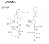
. This is my first Electronic project of this kind. Please find the block diagram of my design
pQM8MHL
pQM8MHL
. Please help me to identify the issue here. Thank you.

EL34 SE with Lundahl LL1664

I'm becoming interested in building the above amp, as designed by Claus Byrith, which specifies a LL1664/80mA output transformer. When I look up the spec of the transformer it appears to a configurable design coping with PP as well as SE but no mention of '80mA'. Is there only one '1664 or does it have to be ordered with a particular configuration? Any guidance would be most welcome, thanks.

PS: I've tried communicating with Lundahl in the past who refer me to their UK contact but they are mostly into pro audio.

Problem with NAD3130 - crackling right speaker

Hi guys, I've recently bought a NAD3130 secondhand. I went through the process of recapping it, and the amp sounds quite good! Unfortunately, once in a while there's a hiss+loss of volume in the right channel: I've swapped cables and speakers to make sure the problem was on the amp.
I've also noticed the balance control is very noisy.
What could it be? Where should I start with the debugging?
I'm thinking maybe some of the solid state components are about to die?

Enclosure Question

here is a simple question ( i think )

On a given unit 8" W 200 S - 8 Ohm of Visaton manu specs say for example

15 l/closed - - 72 Hz/0,75
20 l/bass reflex BR 19.24 (length 14 cm) 45 Hz -
30 l/bass reflex BR 19.24 (length 11 cm) 39 Hz -
50 l/bass reflex BR 15.34(length 13 cm) 33 Hz -

In case one needs to work with these data but the enclosure must have 2 woofers what is the procedure after that ?

One may design a 50 L enclosure and proper bass reflex and stack one at the top of each other ?....

The other might be to have a common enclosure but then how many litters and what bass reflex and where this is going to be located ....

will it be one bass reflex or 2 ?
will it be one bass reflex next to each other
or will it be one bass reflex next to every unit ?

Best soundcard for low noise THD measurement?

Saw the recent announcement for the APx500 Flex. This basically is the AP software, but without the $30k dongle. Instead, you bring your own sound card.

I was just thinking, if I could find a sound card with AP performance, I could get a top of the line AP system for 10% of the cost.

Any sound cards you know that could fit the bill, performance-wise?

Jan

I got Iced !

Looking for some guidance, don't need to hear about not dealing with Ali, have had plenty of good things through them but this time BOOM. See link ICEPOWER power amplifier accessories digital power amplifier module ICE125ASX2 professional grade hifi power amplifier|Amplifier| - AliExpress
[/URL]
the amp is using the ICE125ASx2 module and to my surprise it actually contains that module whether genuine unknown. I have popped the lid and it looks well put together BUT after 24 hours it starts flashing at the power button and no sound. See video. Any suggestions, can it be reset? Is it a grounding issue. Suspicions, solutions welcome.

Attachments

  • VID_20200719_135413.mp4
    5.2 MB

Pre-amp and Class D amp (how to wire for SMPS)

So I have a class D board that I have had lying around for ages. I want to make a small box with 2 x 5" full range drivers for low volume guitar playing. I have a Helix Stomp (amp sim and effects). I want to be able to adjust the bass and treble on the amp because I suspect the small drivers will be lacking in bass. This is for relatively low volume playing so I just want to be able to tweak the bass/treble on the amp instead of the source (I could add extra eq blocks but the unit is limited in how many blocks you can use).

I am going to use an external laptop style power supply.

Actual question:

The preamp voltage is 12v. The amp module can be 9-24v. If I get a 12v external power supply, can I wire the socket to the pre-amp and the amp module with no issues? Or is there a more intelligent way to do this?

Graaf GM400. Speaker protection relay kicks in.

I`ve had this problem since I bouth the amp. Got no help from Graaf as they went out of business short time after. As long as I play my music at low volume its working but as soon as I turn up the volume a bit the relay kicks in. And I have tried several preamps and cd players and its the same. I`ve tried to get in contac with Giovanni Marian and other people from Graaf wihtout any luck. Is there any of you out there that know of any people from Graaf that is stil doing some repair or can help solve this problem.

No sound or clicks from nuforce STA200 power amp

Hi,
I'm a newbi from south korea.
After seeing this forum and it is seemed to here is lots of knowledge about goldmund, nuforce amp, I kindly ask you to let me help out.

I has been used sta200(same design with jobs225, but has half power output) for last three months.

However it sudden dead(power on but no sounds), precisely it does not produces any sound on both channels, and i hear no clicks from it when it turn on or turn off.
Only power engaged led is turning on.

What i recently changed was only preamp to new one from schiit saga.
The new one is holo audio azure.
Heck now i'm thinking azure was the issue that it might contributes to sta200 being broken, because it was feeding by the anomaly signal from azure, and that is when azure's volume muted or at minimum volume level changes, strangely causing pop sound from speakers, along with only azure's such a behavior.

If azure's pre-out can damaged sta200, what part should i check first? i bought it from audio advisor from USA, and i asked nuforce directly but there was no responses.

404 Not Found
Above link, is the left bottom side input buffer? How do you think about the absence of the sound of relay switch's clicking is?
Any advise would be welcome..

Replacement PSU for RJ45 powered Turntable

Hi!

I have an Acoustic Signature Wow Turntable (2013) with a broken power supply (AC-1 PSU), which I lost while moving houses.

The replacement and newer model psu, the AC10, is now more expensive than what the turntable is worth today.

The AC1 power supply connects through the turntable via an RJ45 cable.

Just got back from the Acoustic Signature help email and they suggested that:


You can use any 24VDC power supply bought local and then you need to adapt a RJ 45 cable based on the specs provided.

Power supply should be 24V DC/ 500mA minimum.

That is the only possibility of avoiding the AC10 which would be the only available powersupply.


They also included this schematic.


uix1Cuu.png


So I'm planning to buy an LPS that can do 24v, .8a like this:


OaejzTh.png


and a PoE Injector (which I can let an engineer modify the wiring to connect to the turntable)


Nni7fQy.jpg


Will this work or is there a simpler solution?


As you can see, I am pretty much ignorant when it comes to PSUs and that's the reason why I am asking hahahahahaha.

Here's a pic of the back of the turntable for reference.


YbbTKOg.jpg


Thanks in advance for the help

🙂

Add battery to PE MKBoom kit

I have the MK Boom setup working. However its rated at 50x2 at I believe 21v. Amp is rated up to 24v.
Comes with battery module of 11.1v. You can add another but only for added play time not increased voltage. Any ideas on how I could fairly easily do it?

Dayton Audio MKBoom Portable Bluetooth Speaker Kit

Attachments

  • 20200708_155442.jpg
    20200708_155442.jpg
    904.1 KB · Views: 103
  • 20200721_072624.jpg
    20200721_072624.jpg
    621.3 KB · Views: 102

GU50 SE vs 300B SE tube amp??

Hello
I turn to the forum ( to some expert guys) about my SE tube project.
I start from the beginning so it would be easy to understand my case.
I wanted to build a GU50 SE triode tube amp, so I collected almost all the necessary parts, let say 90%
Power transformer 325V 2.5A, a pair 3.5K SE 10W 100mA continuous bias USA made transformer, driver and power tubes, sockets, choke, PS capacitors etc
Now I don't know do I complete the amplifier or to use those parts to build a 300B SE amplifier.
Do any one has experience with these two power tube, built or heard their sound?
I could use the same transformers, for the 300B , I have D3a tube to drive the 300B, only has one choke 200mA tested up to 2000V (may be I need two)..
What would be the best think build a 300B and sell the GU50 tubes or finish the GU50 and probably I never get close to the 300B performance??Any advise pro and contra welcome.
Also please keep in mind probably later I'll sell the amp because my wish to build a GM70 SE. I just do not want to start with 1000V now, last few years I built only SS amplifier.
Of course all depend the amplifier performance, if sound great I'll keep her.🙂
Also if the amp sound better probably easier to sell in case/.
I do wanted to post pictures from the parts I collected but I have to charge my camera's battery.
So pictures will follow soon.
Thanks for your help
Happy New Year!
Greetings Gabor

Hi, new member, got my hifi mojo back!

hi,got my hifi interest back after about 20yrs,i kept some of my old gear but sadly sold my Klipch horns...and Pink Triangle,sme turntable..😱
anyway i built a SE 300b amp and stored it in the loft,after removing the valves.
recently got it down and dusted off the thick layers that built up,inside looks fine,but after 20yrs kinda forgot all the specs etc..i built it with help from a Guy called Gary,if i remember,who was from Border patrol,again,if i remember.
It has BP interstage transformers and huge output trans,probably bought from BP,if i remember, and lots of Blackgates,silver wire etc,i spent a fortune on the bits..Looks like it has 2 valve rectified ps's for the interstage tranformers and a modified ps for the main choke input 300b ht,all in seperate enclosures,it weighs a ton..any ideas how i can proceed to get it all running again?
I was pretty good with valves/building when i built it but kinda forgot when i lost interest..
searching for circuits and looks similar to a SJS 108 mk2 amp but mine looks like a 2 stage circuit and didnt write down valves i used,the writing on the valves i kept for it have since lost there numbers🙁 so not sure what they were..
Possibly a long shot to sus out what i built but any help appreciated,retired now so lots of spare time to build etc..

KEF R900 crossover upgrade

Hi folks 🙂,

I would like improve the sound of the my KEF R900 speakers by upgrading its crossover parts, and am thus looking for suggestions, advices, feed-back...


You will find attached my pictures of its crossover (world premiere !).

Thanks a lot :hug: .

Douede

Attachments

  • _KEF R900_Filtre_Schema.jpg
    _KEF R900_Filtre_Schema.jpg
    47.1 KB · Views: 1,167
  • KEF R900_Filtre HF_0b.jpg
    KEF R900_Filtre HF_0b.jpg
    49 KB · Views: 1,227
  • KEF R900_Filtre LF_0c.jpg
    KEF R900_Filtre LF_0c.jpg
    35.5 KB · Views: 1,186
  • KEF R900_measure.jpg
    KEF R900_measure.jpg
    35 KB · Views: 1,047
  • Like
Reactions: Zvu

List of Tube Noise Measurements - please nominate lowest noise tubes

I've started to post and maintain a list of noise measurements made on a variety of current production (and a few NOS) audio tubes, because I don't find the lists at the tube vendors very helpful. My list shows the actual input-referred noise of each type/brand and how many tubes of each type I've measured. So far the list is modest, with 7 different types or brands (a total of 38 tubes measured). The lowest noise tubes so far include the JJ 5751 and Shuguang 12AX7B. You can see whole list at
Downloads – Tavish Design

Can anyone suggest other (possibly) lower noise types or brands? I can't afford to buy tubes just to test them(!) - but I do want to identify the lowest noise types, so please let me know your experiences.

Scott

Zobel Or No Zobel ?

ZOBEL OR NO ZOBEL ?????

AND WHY ????

some have exactly after the output of the amlifier the well known 0.1 mfd cap plus 100 R resitor to ground and then followed by one resistor in parallel with a coil .....

some others have first the network coil resistor then the 0.1mfd cap and resistor to ground

once i ve seen coil and resistor network and then from the out of the RC a 0.1 mfd to ground ....

coments about the best technic and also the best arangement between all that is very welcome ......

been working with a mosfet and seemed to play better with 0.1mfd +100R resistor to ground followed by a coil but with no resistor in paralel with it tryied 1R,2R,10R,100R..... but after all sounded better withoutany resistor ...just a coil ...any comments ????

Anyone fancy building/helping me build some amps?

Hi all,

There's currently a guy on ebay selling a job lot of parts for old AudioDigit class T amplifiers. These amps hold a special place in my heart as they were my first entry into power amps years ago.

I'm interested in his stuff and it looks like there's enough there to build a few already. He's said that you can probably get 5 to 8 amps out of the kits with the addition of a few speaker terminals and transformers.

My challenge is that I'm not electrically minded at all. I can wire a plug but that's about it, and my other half is uncomfortable with me building something that'll be plugged in to the house. 🙂 I'm also not set up with things like soldering equipment, multimeters, and other things I imagine you need to do things properly.

My question is, does anybody offer, or know anyone that offers, amp kit building services? I'd love a few of these kits put together and I'd happily reimburse or share the kit.

Thanks in advance

Stuffing guideline

To prevent clogging another forum topic, I'll post my question in a separate topic. The question regards speaker isolation/stuffing.

The situation:
1. I've converted my B&W CM8 S2 (bass reflex port speakers) to active closed box loudspeakers. The drivers are powered by an FA-123 plate amp (hypex). I've done this because I liked the project and my speakers are relatively close to the walls.
2. I've (subjectively!) nailed it with the delay and crossovers of the speakers with a stunning mid- and high performance (thanks to this forum). But the lower end is perhaps as good as it gets, perhaps open to improvement. DIRAC live (full license of my NAD C658) can make de bass response of the speakers more than satisfactory for me, but I'm trying to find out if I should change the inner lining of my speakers. They originally came with 2 cm thick polyesterwool lining over the whole speaker.
3. After sealing the speaker I put a lot of polyester wool (Visaton Damping Material) in the place where the bass reflex port used to be.
4. After reading the 'burrito isolation' post, I removed all the isolation material and installed a burrito of polyester wool. I thinkt he bass got a bit more clear, but I wasn't very sure about the result.
5. I am trying to find out by reading forum post what the most logical inner lining of my speakers would be (floorstanders, relatively small, enclosed). I'm open to trying different amounts of isolation et cetera, but a theoretical guideline would help. I'm satisfied with the sound at the moment, but I would like to use the approach that is most logical.
6. Unfortunately, my understanding of physics is not sufficient to understand all arguments in this discussion, so a direction would be great.
Finally, the mid/tweeter are in a separate wooden cabinet within the floorstanders.

The options would be:
1. Burrito alone.
2. Inner lining alone (1 layer).
3 1 + 2.
4. Complete stuffing of the lower cabinet and no or limited upper.
5. Infinite possibilities...

Any suggestion as to what lining would be most logical?
Where to isolate an how thick? I have pleny of material in stock and can order more if needed.
The outer dimensions of the speaker is 960 mm (h) x 165 mm (w) x 277 mm (d)
The woodwork is approximately 18 mm thick.

Thanks for your help.

Sansui SR-222 MK V PSU recap

Hi,
since I'm in the recapping mood upgrade I recently replaced my Audiolab 8000A PSU Elna 10.000uf 50v caps with new ones more performing Mundorf Mlytic 15,000uF 63v.

Now opening my Sansui SR-222 MK V I noticed there is a probably a ELNA cap like here located lower right.
s-l1600.jpg


In this other pics I found somebody replaced those with Nichicon MUSE KZ 1000uF 50 V.

platine-vinyle-sansui-sr-222-mkv.jpg

platine-vinyle-sansui-sr-222-mkv.jpg


If I'd like to upgrade the ELNA with Mundorf MLytic caps, would it be ok replacing with a new Mundorf MLytic AG 1000uF 100V.
Is it compatible? Will it make a change on the sound?
I noticed a couple of other smaller Elna caps there that might be subject to replacement too.

Long Overdue SE Build

Long Overdue SE Build need help troubleshooting

So this is about 10 years in the making. This was a 2A3 that is about 10 years old.

Edcore Power
Electraprint TM3Kb outputs
Maple/Walnut base
Aluminum top plate

The wife picked out the blue color for me on the trannies. Hoping to have this done in a couple months.

Painted w/spay cans.

Thanks,
Jeremy

Attachments

  • IMG_1339.jpg
    IMG_1339.jpg
    617.4 KB · Views: 408
  • IMG_0275.jpg
    IMG_0275.jpg
    706.5 KB · Views: 415
  • IMG_0391.jpg
    IMG_0391.jpg
    504.9 KB · Views: 397
  • IMG_1192.jpg
    IMG_1192.jpg
    547.9 KB · Views: 398
  • IMG_1193.jpg
    IMG_1193.jpg
    500.8 KB · Views: 392
  • IMG_1194.jpg
    IMG_1194.jpg
    667.8 KB · Views: 191
  • IMG_1198.jpg
    IMG_1198.jpg
    546.9 KB · Views: 181
  • IMG_1247.jpg
    IMG_1247.jpg
    454.8 KB · Views: 145
  • IMG_1248.jpg
    IMG_1248.jpg
    469 KB · Views: 171

Anybody try this phono preamp ?

Hello

I've just found that phono preamp this morning.

Phono Preamplifier - RED - Page10

I would use another opamp than the LM833.

Anybody try this phono preamp, any opinions or suggestions about it ?

Technical data:

Featuring low noise, good RIAA frequency response curve, low distortion and good high frequency transients behavior due to passive equalization in the 1 to 20KHz range.

Sensitivity @ 1KHz: 2.5mV RMS input for 200mV RMS output
Max. input voltage @ 1KHz: 120mV RMS
Max. input voltage @ 10KHz: 141mV RMS
Max. input voltage @ 20KHz: 127mV RMS
Frequency response @ 1V RMS output: 100Hz to 20KHz ±0.5dB; -0.75dB @ 30Hz
Total harmonic distortion @ 1KHz and 6V RMS output: 0.006%
Total harmonic distortion @10KHz and 1V RMS output: 0.02%

Thank

Bye

Gaetan

Attachments

  • phono.gif
    phono.gif
    10.7 KB · Views: 508

Small Visaton recommendation please

Hi guys,
I have a WAW or FAST or whatever the're called these days that consists of a Dayton DC300 and Markaudio CHR-70.
Minidsp, 4 chinese amps, xo 300Hz, 48db/oct (just because I can🙂 Didn't even test other slopes).


I find the chr-70 a bti harsh and beaming, so I want to try another, smaller driver as a FR unit, and I want it to be a Visaton, because they offer really a lot of good small fullrangers, and I can get them quite easily at work.


However, I can't decide between

FRS5x (people's chioce, so it seems)

FR58 (super flat, no published directivity pattern)

BF37 (kinda low efficiency, but should be sweet as a midhigh??)


The driver will reside in a 6l sealed, heavily damped chamber, probably not even important, since it will only ever be used at 300Hz+.

EL34 data sheet - operating points

Looking at the Mullard data sheet, I quickly drew the load line for the recommended 400V operating point. And verified it with an online "calculator". All the numbers come out very nearly identical. But the load line cuts significantly outside of the SOA. Like, by a whole bunch. What am I missing here? The Brimar data sheet shows the same.

Attachments

  • Capture1.JPG
    Capture1.JPG
    87.3 KB · Views: 1,029
  • Capture3.JPG
    Capture3.JPG
    154.9 KB · Views: 625

HELP! With Component Identification

Hi guys. I've been busy with other things so not been bothering anyone around here lately...

But I have another work related question:

We have some old (50-60 years old) equipment which uses Allied Control open relays (contactors essentially) for the control logic- turning on and off etc. The main one is going bad (or is already bad) in a couple consoles.

I have three 'tested good' contactors I farmed out of a donor, but when comparing to a "good/working" console, I notice what I had originally thought might be a arc suppressing capacitor, but now I'm not sure what it is exactly. (shown as "D3" on paperwork)

Checking the ancient scrolls for schematics/wiring/build diagrams, the part in question is listed as "Selenium Thyrector Diode" No value listed. (pic 3&4)

The part itself has "1501" (I think) on the top line and "GEV1" on the bottom line. (pic 1&2) My google-fu has proven to be found wanting... Note this is the "newer" console (from 1978 I think) and what is most interesting is that this component, though shown on the wiring diagram, is not listed in the parts. The older diagram (early-mid 60's) calls it out, but no value as noted above. (pic 4)

I know you guys know more about this stuff than I ever will, so any ideas on a direct, or current production replacement, for this little guy? It does not seem to have any polarity, and is on the 110VAC line of the main contactor. Is it critical to proper operation of the contactor?

(I want to pre-set these contactors so the maintenance tech can "drop" them in, without dealing with any soldering or other stuff. I'll number marker the wires and he can just crimp connect them in to the correct numbered wires.)

Looking at the schematic, the symbol is drawn like two diodes butting into one another: ->|<- with one side going to the "hot" contact and the other going to the "neutral" contact. (pic 5) Both contacts are on the same contactor, powered by a shared coil, which gets power prior to this component- the component is on the open side of the contacts, bridging hot and neutral. So, it has no effect on the coil itself as far as I can tell.

1) what was the intent of this?
2) what is a currently available replacement I can spec in? (contacts are rated six amps max)

Thank you guys for reading, and hopefully pointing me in the right direction!

Attachments

  • IMG_9503.jpg
    IMG_9503.jpg
    828.1 KB · Views: 143
  • IMG_9505.jpg
    IMG_9505.jpg
    652.1 KB · Views: 134
  • IMG_9506.jpg
    IMG_9506.jpg
    728.7 KB · Views: 132
  • IMG_9507.jpg
    IMG_9507.jpg
    701.2 KB · Views: 136
  • IMG_9508.jpg
    IMG_9508.jpg
    772.5 KB · Views: 140

THD going down from 100ppm to 1/100 ppm in 4 versions of a 100W@8R / 200W@4R buffer

As a DIY challenge, I followed for my Main Amp a route where gain and power were split over resp. a very fast low power 27.5dB voltage amplifier followed by a separate 0dB buffer.
I’ve seen others doing the same like Jan Didden around a AD844 and LKA with discrete transistors.
They both used the so called Hawskford Error Correction or HEC.

HEC implementation is an (active) error correction principle around a 1x gain correction stage that subtracts the difference between input and output from the input.
This can theoretically reduce all distortion, but practical designs do need very precise tuning and a very careful choice of topology.
It cannot compensate the distortion caused by the input adder and neither does it correct the Amp’s output offset.

There are other Active Error Feedback principles, with more flexibility not needing any tuning at all and at the same time taking control of the Amp’s output offset voltage.
The most simple version is called FDR (feedback distortion reducer) that only needs one op-amp, a resistor and a bandwidth limiting cap around said op-amp.
In case of a high voltage buffer, this op-amp asks for a floating supply driven by the Amp’s output. But there's more to reduce distortion as will be discussed.
The 4 versions will be shown in four postings, so here's the first one.

Version 1

The first version in this thread is a straightforward 3 stage buffer, equipped with modern transistors taken from the Cordell models.txt library, such as often used on this DIYAudio forum, nothing special, but perfectly suited for the purpose of this thread.
Idle current chosen was slightly below 300mA, giving a flat FR from a low impedance source.
In the attached image the circuit diagram is shown for the used buffer, together with its THD for 8R and 4R @ 10Khz versus power from 1Watt to resp. 100Watt and 200Watt for both loads.
Idle current in one of three output transistors, as well as the output offset voltage are visible in the diagram.
THD lies between 0.1% and 0.01%.

Hans

Addendum: Distortion figures presented in my images are not to be confused with percentages.
So 1e-2 = 1%, 1e-4 = 0,01% etc.
With the same logic, 1ppm is 0,0001% or -120dB.

Attachments

  • Version1-3EF.jpg
    Version1-3EF.jpg
    247.4 KB · Views: 722

Klipsch RPW10 Troubleshooting

My Klipsch RPW10 suddenly started blowing fuses the moment the power switch was turned on. I contacted Klipsch and they have sent me a full set of schematics. Can someone lead me through some basic troubleshooting so that I could possibly identify the problem, identify the failed components, and from there I can hunt down the parts that need to be replaced. I have a rudimentary knowledge of electricity, and have repaired everything from VCR's to failed automotive key fobs. Any help and guidance would be very much appreciated. I like challenges and I like to save money.

Dennis C

Phillips 212 turn table dead. Seems like power supply issue

Turn table had issues with lights flickering.
This turn table used touch buttons
Motor and all bulbs work. I tested them with 5v DC power.
Control board is simple. Not much soldered on there just can't figure out which component is bad.

One other thing I found out is that transformer is dead. Outputs like .012v or something close to 0v
I used one old charger that outputs 13v DC. Which is close enough to original 14v charger. When measuring PS supply voltage after rectifier diode Ii get 11v or so. Manual says it should be 9v. Maybe I am measuring wrong

When plugging in new 13v DC charger to the board I don't get any signs of life. Touch buttons don't lite up. I attached service manual.
Was hoping to step by step go through this circuit

Here is the link to service manual

https://www.google.com/url?sa=t&sou...Vaw2FBY7ax4ES90rV8q6BcNd9&cshid=1595395741320
Projects by fanatics, for fanatics
Get answers and advice for everyone wanting to learn the art of audio.
Join the Community
507,781
Members
7,888,175
Messages

Filter

Forum Statistics

Threads
406,225
Messages
7,888,175
Members
507,781
Latest member
Ronny2001