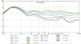
Klipsch RF15 or RF63

I have owned a pair of Klipsch RF15 for about 15 years now. I am satisfied with the sound, but I saw a pair of RF63 for sale in the neighbourhood, and I wonder, are RF63 a better loudspeaker than the RF15. I use different amps, an EL84se, an DIY Hypex class D, NAD 216, which amp depend on the mood I am in? But I liked the sound of my EL84SE, triode wired and about 1,5 watts!

Fostex FE108e∑

Hi all,
I thought build my first loudspeaker project using the Fostex Fe108e∑ drives, but recently I listen that the quality of Fostex fall down because it's not a genuine japan product that were in the past, I like know yours opinions and experiences with these drives and at the same time I will like to know if anyone has some projects with the Fostex Fe108 E sigma to share .
Thanks a lot in advance of your shares.
Regards,
Joaquim Bento

Need help with this guitar junction box system

I recently designed a junction box system for the 4-cable method of routing a guitar and effects to an amp and fx loop. It's designed to work just like any junction box (by just connecting the input directly to the corresponding output in the back). However, I added a switch which allows you to take all effects out of the fx loop of the amp and routing them in series with the other effects and have them all go in front of the amp, bypassing the fx loop.

This is the simple design.
30jxz1QM


It works, but it makes a lot of noise (just like a guitar that is not grounded). I know it is probably a design flaw that causes ground issues, but can't figure out what it is and how to solve it. Any thoughts?

Thanks!

Leaky supercardioid mids

So far I've been focused on controlling directivity for the tweeter (as seen in the 3D-printing thread here) which looks something like this (0-75 deg):
492164d1436128095-3d-printing-npdv543.jpg


I feel I'm closing in on something that I want to try in a speaker (not just measure). But then I need something for frequencies between ~150 Hz and 1500 Hz (below 150 I have subwoofers and that should be below the Scroeder frequency, i.e. directivity is not necessary). I need to place the speakers close to the front wall (~20 cm) so the most suitable polar patter should be supercardioid:
An externally hosted image should be here but it was not working when we last tested it.

(Image borrowed from kimmusaunisto.net)

I found this website:
Cardioid bass
And decided to give one of my test speakers a set of holes to test the leaky box approach:
IMAG0500.jpg
This is with 16 1" holes on each side, slightly above Sd for two 5" woofers.

First a measurement of the speaker before any holes where made (0, 30, 60, 90, 120 and 180 deg):
511876d1446243089-leaky-supercardioid-mids-closed2.jpg


Then I made 8 holes on each side and measured again (0, 30, 60, 90, 120 and 180 deg):
511877d1446243089-leaky-supercardioid-mids-16-holes.jpg

I assume the hump is due to the fact that the box behaves like a ported box at low frequencies. Can that be solved by adding more holes?

This is with 16 holes on each side (0, 30, 60, 90, 120, 150 and 180 deg):
511878d1446243089-leaky-supercardioid-mids-32-holes.jpg

The hump is moved up in frequency, but separation between lines is better. Lowest SPL is observed at 150 deg, then 120 and then 180 deg.

All measurements at 1.5 m distance, 1.5 m above ground, no gating, psychoacoustic smoothing.

I have not added any resistive element to the holes, but there is some ~polyfill in the speaker. The results are decent, what would adding resistance do?

Questions:
1. What should I do to get directivity to reach down below 200 Hz? Add more holes, resistivity?
2. What driver parameters should be suitable for this type of application? Any examples below 100 USD each for ~7" drivers?

/Anton

Attachments

  • closed2.jpg
    closed2.jpg
    73.4 KB · Views: 2,788
  • 16 holes.jpg
    16 holes.jpg
    77.3 KB · Views: 2,206
  • 32 holes.jpg
    32 holes.jpg
    80.9 KB · Views: 2,195

Balanced Input / Output IC's vs Discreet - real world performance

Hi, I've been reading through Self's Active Crossover book and I was looking over the various reference designs for balanced input and output circuits using opamps and other passives.

Then I stumbled upon an article about the THAT 1200 IC. I also noticed ICs built for balanced output.

Has anyone used these?

In real world performance do they outperform discrete circuits?

It would seem much simpler to just use a chip... This also seems to be a common enough application that TI should have a single chip for this...

Creating the 'virtual ground' in a single supply preamp/amp circuit???

I am building a single supply (24V) preamp and amplifier circuit that uses about 8 op amps for active filters and 4 LM3886 amplifier IC's (High and Low Bridged Outputs).

What is the best way to create a steady mid-rail voltage (VCC/2) for a reference voltage (also known as virtual ground) for the opamps and LM3886 IC's?

At the moment, I am trying an op amp follower circuit similar to the one shown on page 2 of this document http://www.analogzone.com/avt_0806.pdf (i originally didnt have the small resistor on the output and got oscillations from the op amp. the small 47R resistor fixed this)

I am using an LM324 op amp for the follower. (have a spare one available on the board). Can I also add a large electrolytic cap (68uF) to the follower output for filtering/regulation?

Alps potentiometer awful channel imbalance

I think my Alps RK27112A00AK stereo log audio potentiometer is broken?! The left channel is completely muted until I turn the knob around 50% now.


I only had it for several months, too. Is there a way to repair? Should I be adding resistors to it to improve the tracking? Should I try to replace it? Should I switch to a stepped attenuator?

I would prefer to have my digital source audio at 100% and rely on the potentiometer for the volume to reduce bit crush.

Cambridge A500 Sudden Death

Hallo DIYers

Yesterday i had the experience of my trusty A500 amp out of nowhere, driving 4 ohm speakers, suddenly having the right channel dying completely.

Not longer than 30 minutes later, the left channel died as well.

Two red diodes have lit up inside the cabinet, nothing other than that looks out of the ordinary.

Does anyone know what the next step in finding the problem here and if its fixable?

I hurried out and bought a NAD320BEE to replace it, as i had no other amp at that specific time, but i would very much like to bring back the A500, as it had a great sound and many solid qualities to it.

Should i visit a technician about this?

Thanks alot, you HiFi wizards!

3 way position (vertical or horizontal)

I am assembling a 3-way, composed of a Celestion 1746 CD mounted in a MCM 54-580 / Pyle PH65, a Faital 6FE100 Midwoofer and a JBL 2226H woofer.

Both woofer will be on sealed compartments and will be crossed over my subwoofers around 70-80hz.

The crossovers will be active around 400hz and 2200hz.-

Considering the space I have in my room, a horizontal mounting of the components and a horizontal speaker it's much better, but what are the problems from a sound quality and "stage" perspective?

I have DSP capabilities for each component and this will be used for "in home" usage.

So, would you recommend to arrange like: waveguide > midbass > 15" woofer, mounted in vertical position or would it be better to mount the waveguide and the mid like a standard two-way and woofer on the side?

Looking forward to your help!

Attachments

  • Captura77.JPG
    Captura77.JPG
    200.5 KB · Views: 182

Collection of rare 6AK5 EF95 6J1 5654W 6P1 403B 6AQ5 equivalents tubes mostly NOS so

8MM6QvF.jpg


JjKpEfX.jpg


$100 shipped.

these are all equivalent driver tubes:
LM Ericsson 5591 / 403B (quantity 3)
Western electric 403B (quantity 1)
Voskhd 6J1-EV rocket logo (quantity 2) glass has glue residue so its ugly but works as new and perfect
Amperex bugle boy EF95 (quantity 2)
EI Tugoslavia 6HM5 ( EC900 6HA5 6HQ5 ) (quantity 3)
RCA 6AK4 NOS matched pair
GE 5654W (quantity 1)
and a few more i dont remeber

these are all equivalent (the 6AQ5 needs an adapter which is included in the price) power tubes
Brimar 6AQ5 used (quantity 2)
Tung Sol 6AQ5 NOS quantity 3
wing C 6P1-EV quantity 2 NOS vintage 1988 matched pair
wing C 6p1-EV vintage 1976 NOS mathed pair
2 gold pin adapters for 6AQ5 to 6p1
and a few more that i dont remember

tonearm cable question

I recently came across some surplus cable that I think may make a good tonearm cable. The cable is composed of two stranded parallel conductors, with two concentric braided shields. The shields are insulated from each other and the conductors with layers of teflon.

I plan on terminating to a 5 pin DIN connector (tonearm end), and RCA connectors on the other end, using one 1.5m length for each channel.

My question is about the two layers of shielding. What are your suggestions for terminating the shields? From what I understand, the usual configuration is to terminate the shield to ground at the RCA (input to pre-amp) connector. What do you suggest for the second shield? Should I also terminate it at the RCA connector?

Any advice will be welcome

Pair of Seas CA18RNX and Seas 27TDFC

Have these still boxed up and unused. Bought from Falcon Acoustics last month for a project but won't be getting round to it. Too late to return so offering them here if someone can make use.

Paid £80 for the tweeters and £144 for the drivers so wanting to get a reasonable bit back as they are mint.

If you want to buy all of them I'll cut a deal. P&P would be extra in the UK

Links:
Seas CA18RNX
Seas 27TDFC

Kef Kube 2 repair

Hi all

I needed some help regarding my Kef Kube 2 subwoofer
It recently stopped working and I sent off the amplifier part of the subwoofer to Kef to see if they could repair it. They were very helpful but unfortunately they discovered that there was alot of damage/burnt out areas on the power board and recommended I buy a new amplifier part to install into the enclosure.

I wanted to know if anyone has had a similar problem with this particular subwoofer and managed to fix this problem?
I have attached images of the subwoofer and also images of what Kef sent to me of the PCB of the amplifier and power supply

If this isnt worth the hassle could someone recommend an amplifier/power supply I could buy cheaply enough to carry on using my subwoofer until I am ready to either buy the replacement amp or even buy a new subwoofer.

Thanks in advance

Sansui 551

Dear Everyone,

I am working on a Sansui 551 Stereo Receiver belonging to a friend. Its left channel was dead. One output transisitor (2SD315) and One Driver (2SA697) were shorted. I replaced both the parts but within seconds they blew up again. One further checking, I realised that a Diode mounted on the heatsink has open. From the schematic, I realised that the diode part number is SV-03F. I cannot get the datasheet for this part as it is obselete. I guess it is a NTC diode to increase the resistance and control the current as the heatsink heats up. I cannot get this part from any electronic parts dealers locally. Can someone advice me on a replacement part number or how to modify this circuit and the actual function of this part. Please help as I am still a junior as far as repairing is concerned.

Thank you


Carlosraj

Replacing Velo DD12 amp

Hi, I have a Velodyne DD12 that produces distorted sound due to damaged electronics. The driver and the box are still in good condition. Has anybody ever tried to replace the plate amplifier of this sub with some generic DIY plate amp? Any suggestion on which plate amp will fit the form factor of the original module? I know that doing so, I will lose the servo feedback feature as well as some other control features of the sub, but I am fine with that. Will I be getting a good bass response by using a replacement plate amp assuming there is one that fits? Will appreciate any suggestion that you guys might have in utilizing the still-good driver and cabinet of the sub.

Power supply fault in preamp

Please help!

I have no experience with tubes and I'm stuck on a problem. I've had a preamp for a while by Assembelage L-1

There is no high voltage and I cant figure out what is going on. I have tested all resistors and caps and diodes. I bought a nice transistor tester from China that tell me my Mosfets are fine but it doesn't even get that far.

the problem is before the resistor marked 1M5 there is very high voltage but after is only 16v! Its not supposed to be that low. Please what is going on? I waited a week for the resistor only to find the same result!

Any help appreciated!

Attachments

  • Assembly.jpg
    Assembly.jpg
    367.5 KB · Views: 291

2-way passive open baffle

Just looking for feedback on an idea I have for a passive two-way open baffle speaker.

I've got four of these Peerless SLS 12" 830669 woofers (see attachment for specs) that I'd like to make something with. I'm thinking of using them on a baffle not too much wider than the woofers themselves, so about 350mm wide. However this is somewhat flexible, I could stretch it out to maybe a ma of 450mm

I'm thinking of crossing over somewhere between 150-300hz or so to some widerange 4" Mark Audio CHR-70 (see attachment for specs).

For aesthetics I want to keep with a simple U-frame baffle, with all drivers firing forwards. I'm looking to do a regular height floorstander (approximately 1m)

What do people think in terms of feasibility? Any anticipated major difficulties or things I need to rethink before proceeding and ordering parts/wood etc? Will things work out with matching sensitivities of these drivers? As there will be two woofers per side, will it work wiring them up in parallel for a 4ohm nominal load. Good idea? Bad idea?

Any ideas or feedback is welcome

Attachments

Plenty of excursion, no *******' bass!

I have built a 16ltr test cabinet for 6.5" drivers. I am fascinated by the behaviour one particular unbranded driver. It seems to be [British expression]: all fur coat and no knickers. It would look good on a Youtube video, bouncing around like it's having a serious affect on the Richter scale but it doesn't produce any actual bass. Of all the drivers I have laying around it has the weakest suspension.

Can somebody point me in the direction as to why it would be a disaster?

I can only guess that it was designed for a very small sealed cabinet.

FS: “New Generation” Dynaco St-35 clone

Built from a kit, the ST-NG is a stereo tube power amplifier based on the Dynaco ST-35. 17.5W/ch. The power supply comprises the high voltage, regulated dual bias adjustment, and regulated DC filament supply. Bias is adjusted externally from back panel jacks, and a separate meter specifically for the adjustment is included. The amplifier is an improved ST-35 circuit, with both channels on one printed circuit board. Tubes are GE 7247 and (2) matched JJ Electronics EL84 per channel. Transformers are Dynakit original spec parts. The amplifier is housed in a Par Metal chassis and rests on Cary Audio isolation feet. Alps Blue volume potentiometer.
Note: This is not an Erhard Audio product. I built this from an electronics kit from the company.

$500 plus shipping to CUS only

PM for photos or with questions

17 foot pipe sub 12-230 Hz ±5dB

The sub has two parts, a base holding a 15-inch, 1965 Stephens 150W, and a 17x17x72-inch box mostly ¼ inch plywood weighing about 45 lbs, containing three tubes (with two abrupt bends) with sound exiting from the top.

The first pix shows an average of 3 mic positions near my chair. No EQ or crossover filter. Can't say for sure if bottom bass is as it should measure, but that's 12-230 Hz ±5dB (which I ordinarily cross over around 130 Hz). Nice.

The second and third pix shows near field sound outputs at the driver and at top exit. In each, you see the very lightly absorbent versus final stuffed (roughly the familiar .5 lb per cu foot). You can see the weird pipe effects. Something's cooking at multiples of 8.5 Hz.

The fourth pix has five impedance curves. The top and bottom are 47- and 7-Ohm resistors to benchmark the curves. The big bump at 26 Hz is the free-air driver. The smaller bump is in the lightly stuffed. The all-but-flat final curve near the middle is the stuffed pipe.

B.

sb23nrxs45-8 simulations and reality

Okay,so a few days ago i finished my bass modules using these drivers , 37 l , simulated in winisd , tuned to 31 hz , 22 cm long port ... frequency response should fall off smoothly with +1 db boost in bass region according to simulation , with - 3 db at 40 hz . Now , in reality when i play bass sweep the bass starts to play right from 30 hz up to 41 hz then drops in volume between 41-51 hz and starts climbing again fast from 52 hz . Is the reason for this :
a) simulation program sucks
b) it was desigend properly but my room acoustics sucks out bass in that region.
c) the speakers are not broken in and they will fill that hole once they are broken in ( i doubt it )

Should this speaker be tuned to 38-40 hz ?
If anyone has this speaker in simillar sized enclosure please tell me how it behaves and what frequency was it tuned?

A big "Hi" from a console guy!

Hey folks, greetings from London, Ontario, Canada.

Over the last year or so, I've used many of your discussions to inform a rebuild of an older (1967) console stereo. So, I'm hoping to add to your considerable knowledgebase by chronicling my build in hopes that the next person to take on a console upgrade can benefit from my learnings like I did from your experiences.

Looking forward to collaborating with you soon.

5654 (6ak5) line stage in triode mode

Finally I decided to start projecting a new line stage with 5654, unfortunately I’ve got 35 of this tubes and in Naples the garbage collection is a main problem now so… I’ve to use them!!! Moreover this is the first time for me and I’m sure that 35 tubes are not enough before i get the goal. Therefore I need some help from you , this is the schema I’ve designed, please give it a look and give me any useful correction and/or suggestion.

Thanks
Francesco

Attachments

  • 6ak5.jpg
    6ak5.jpg
    17.8 KB · Views: 3,942

42v to +/-24 DC-DC isolated buck-boost converter 10A

Hello Everyone,

I have 3 car batteries in series in order to power my amplifier. They are charged with a simple linear PSU. For many days I am trying to find a controller that I could drive my buck-boost circuit with and keep the output voltage stable. I have been through many dozens of products of many manufacturers but I just can't seem to be able to find what I need.

Did any of you stumble upon an IC that could do the job?

Many thanks in advance.

Need advice - mid-range speaker design

Hi guys

I need your advice. I am looking for a mid-range self build. I have a CNC and the required tools, so can do the cabinets myself, but I don't have the knowledge and the desire to design a cross-overs myself, so want to opt for something existing that is proven and sounds good.

I am open minded as to what type of speaker - floorstander, compact on stands, etc.

My sound style is literally across the the full range of music styles (classic to hard rock) with Jazz/Fusion my most listened to genre. Thus, I need something that is a good allrounder with a top mid-range. I do enjoy a solid, tight, clean base, but nothing crazy.

While looking around, I came came across a few open source designs by good driver manufacturers, like:
- ARA – Sbacoustics (driver cost £401)
- Arya – Sbacoustics (driver cost £1052)
- IDUNN (driver cost £306)

Are those designs any good? I think both SB and Seas have an excellent reputation. Or could you point me in another direction where I could find a good open source design (cabinet & cross-over)?

Thanks very much for your help.
Phil

SDR widget PCB group buy (USB 24/192 IN-OUT)

Hello,

I need to my own use an experiment of my DIY project based on LCT2380-24 ADC to build a SDR widget CPU board.

So, the designer of th SDR widget hardware (Yoyodyne consulting) doesn't provide this board anymore.
Anyway, as the project is fully open sourced he provide Gerbers of the design and all stuff needed to build the board without issue.

So, to avoid the big cost of doing a single PCB order, i post here
to know if there is others DIYaudio members that would be interested
to join a group buy to get a bare PCB of the SDR widget.

The goal would be 10 PCB.

For this quantity, the unit price would be 20€ each. This price include one bare PCB,
the worldwide shipment to you and Paypal fees. I will ask payment using Paypal only.
The final price will be lower if we are more (15€ of we are 20).

PCB will be ordered to WEdirekt in Germany, with ENIG(gold) finish and silkscreen.
No parts are included.

The group buy will be closed as soon we reach 20 buyers, or at the end of this month
if there is less buyers.

To recall a little, the SDRwidget is an open source project of USBaudio
interface that is capable to send/receive audio stream from 24bits
48kHz / 96kHz and even 192kHz (playback and record mode).

You can found many information HERE.
I is supported by all OS.
Many information about software and firmware using Google search.


SO i add me here on this first post below in the list of buyer : NEW PRICE 5 € !
---------------------------------------------------------------------------------
PCB ARE AVAILABLE NOW, PM ME IF INTERSTED
---------------------------------------------------------------------------


Pseudo --- Qty ---- Location
----------------
Frex x1 France - Done
Turbon x2 Sweden
mroether x2 Germany --- Payment ok -- Shipping done
BDL x1 Romania --- Payment ok -- Shipping done


----------------

Regard.

Frex


A picture of the SDR Widget :
SDR_Widget_Lite_CPU_Alpha2_Top.JPG

Op amp + Vfet 's 60|18 = Seychelle

Share this schematics if you have 2SK60 and 2SJ18 in your drawer.
Simple build use only half of the op amp and pair of Sony vfet's.

Attachments

  • A544E334-5392-462F-B064-87D72DB06C9B.jpg
    A544E334-5392-462F-B064-87D72DB06C9B.jpg
    365.7 KB · Views: 706
  • 3F766587-BB5F-422D-9FDE-148CF15FFBB4.jpg
    3F766587-BB5F-422D-9FDE-148CF15FFBB4.jpg
    169.6 KB · Views: 711
  • 8ABC87B0-E26E-4963-AF3F-5725EA0B7BF6.jpg
    8ABC87B0-E26E-4963-AF3F-5725EA0B7BF6.jpg
    169.7 KB · Views: 714
  • F4E7684E-3104-4CC0-A408-5933DF370294.jpg
    F4E7684E-3104-4CC0-A408-5933DF370294.jpg
    496.6 KB · Views: 700
  • 8618FBB9-E250-418B-A2EB-E02DB5E1835E.jpg
    8618FBB9-E250-418B-A2EB-E02DB5E1835E.jpg
    223.2 KB · Views: 678
  • 0204D142-ECCD-4C0C-A153-84D6C91A177A.jpg
    0204D142-ECCD-4C0C-A153-84D6C91A177A.jpg
    407.1 KB · Views: 349

Nichicon Muse ES bipolar caps measured: <-120dB THD, <-140dB IMD

Hi folks, as a few of you may know from my occasional posts, one of the DIY areas I tend to focus on is design of composite amplifiers. The performance of well executed composite amplifiers tends not to be measureable as it exceeds that of high end test and measurement equipment (more on this a few pages in on the Modulus-86 thread if you're interested) and the most attractive approach in a design I'm currently working on is DC blocking caps. I wished to know if the capacitors would limit performance.

It happens I'm in Seattle on a business trip this week. So I made arrangements to visit Neurochrome Audio to get the caps assessed on Neurochrome's APx525 as part of the test services Tom offers. If you're not familiar with the APx525 it's a USD 12k or so audio analyzer which is (currently) the second best bit of audio measurement kit available---its performance is exceeded only by the APx555, which runs around USD 40k. (My current car is the best I've ever owned and I bought it new for USD 13.1k. 😉)

Nichicon's ES series is quite linear when there's less than about 400mV RMS developed across the capacitors. The graphs below show representative THD+N and IMD; at no point were we able to obtain results where the caps rose above the APx525's measurement limits. Below 500mV or so RMS THD+N is limited by the AP's approximately 1uV of audio band noise (20Hz-20kHz) and by the best linearity available within its range switching at larger swings---all traces including loopback on the AP group on top of each other, from 20Hz at the bottom to 7kHz at the top (loopback gets shortened to loop or loopb in the trace labels). IMD is also limited by the AP's function generator with the location of the spur frequencies shifting depending on the DC offset applied. 0 and 1V offset are shown; there's no discernable difference among the various traces as they're all identical within the limits of measurement repeatability. This held to the largest offsets tested, ±10V. Parts measured are the 6.3mm ES lineup; 4.7uF 50V, 10uF 35V, 22uF 25V, 33uF 16V, and 47uF 10V. Elna bipolars weren't measured as none of the distributors I use stocks them.

The thread title is conservative for the passband of DC blocking applications. Since the measurements don't budge when the cap under test is inserted one can infer the cap's nonlinearity is neither increasing or cancelling the AP's nonlinearities. In these charts the limit of measurement repeatability is a bit under 0.1dB on the -124dB spurs shown, corresponding to the -145dB or so noise floor (the test signal is 0dBV RMS so IMD can be read directly off the graphs). Therefore, the IMD of the caps is -145dB or better. Worst case THD is likely rather better than -130dB.

For perspective, the APx525's 1uV noise is the audio band Johnson noise of a 3k resistor. Very quiet audio op amps, such as the LME49710, have to be operated with feedback impedances of 600 ohms or less to achieve this noise floor. The -124dBV spurs are 630nV RMS, which requires a 180 ohm feedback impedance to beat---achieving similar performance in the amplifier I'm building is possible but requires either very special case optimizations or spending a few hundred euro on precision resistors. Finally, the IMD graphs are labeled Demo Mode as I put them together after the measurement session. Running AP's software without the analyzer attached requires operation in Demo Mode and I elected not erase the label in Photoshop.

Attachments

  • NichiconES-THD.png
    NichiconES-THD.png
    76.9 KB · Views: 3,849
  • NichiconES-IMD-0V.png
    NichiconES-IMD-0V.png
    88 KB · Views: 3,743
  • NichiconES-IMD-1V.png
    NichiconES-IMD-1V.png
    91.3 KB · Views: 3,705
  • NichiconES-IMD-0V-zoom.png
    NichiconES-IMD-0V-zoom.png
    68.7 KB · Views: 3,637
  • NichiconES-IMD-1V-zoom.png
    NichiconES-IMD-1V-zoom.png
    63 KB · Views: 3,718

FS: CLEARANCE: Various PCBs - Headphone Amplifiers / D-Noizator (EU Only) FREE UK P&P

FS: CLEARANCE: Various PCBs - Headphone Amplifiers / D-Noizator / FREE UK P&P

I have a few spare PCB's for made from the original design files. These are spare boards which I have left over from a fabrication run (due to minimum order requirements) and are therefore sold for DIY purposes only and not for commercial gain. They are to cover board, build and shipping costs to me, not for profit. Once they are gone, they are gone.

PAYMENT AND SHIPPING:
  • Payment by Paypal "Friends and Family"
  • UK - Free untracked P&P for orders over £5, additional fee for Signed-For.
  • EU/US - As per Royal Mail: Get a price | Royal Mail Group Ltd
  • Payment within 48 hours before being released from reserve

Die-Noizator 5-36V PSU, PCB designed by me, schematic by Elvee/diegomj1973
D-Noizator: a magic active noise canceller to retrofit & upgrade any 317-based V.Reg.
Single rail positive PSU 5-36V.
Onboard transformer solution (Talema/Amveco/RS Pro toroidal series)
EMI filter, transformer snubber, CRC, LM317, Sziklai Pair Die-Noizator. Extremely low noise PSU.
220-240V primary. Secondaries can be jumpered parallel or series.
None available £6 each, 100g 'Letter'

  • 1x jean-paul (GER) Dispatched
  • 1x giaspyr (GRE) Dispatched
  • 2x ml48 (UK) Dispatched

Die-Noizator 5-36V, PCB designed by tombo56, schematic by Elvee/diegomj1973
D-Noizator: a magic active noise canceller to retrofit & upgrade any 317-based V.Reg.
Single rail positive PSU 5-36V
Offboard transformer.
None available £4 each, 100g 'Letter'

  • 1x giaspyr (GRE) Dispatched
  • 2x JRKO (UK) Dispatched
  • 1x indaco (ITA) Dispatched
  • 1x capslock (GER) Dispatched

Objective 2 Headphone Amplifier designed by NwAvGuy
NwAvGuy: O2 Details
2x available £8 each, 100g 'Letter'

  • 1x capslock (GER) Dispatched
  • 1x Gregje(UK) Dispatched

WHAMMY Class A Headphone Amplifier designed by Wayne Colburn (Pass Labs)
"WHAMMY" Pass DIY headphone amp guide
None available- £18 each, 200g 'Large Letter'

  • 2x Itsmee (UK) Dispatched
  • 1x capslock (GER) Dispatched

Note: This is based on Wayne's original design files from 2017 which do not have the optional input resistors (R39/R40). These are included in the latest revision to add some input impedance which makes the amplifier more stable using some older audio sources. However, they are optional and can be added between the input pads and the input RCA connector if required (see schematic). For the newest, supported PCB revision, please see diyaudiostore.com

Alps RK27 Blue Velvet Mounting Board
7x available £3 each, 100g 'Letter'

  • 2x davidjt (UK) Dispatched
  • 2x Itsmee (UK) Dispatched
  • 2x Slinkymalinky (UK) Dispatched
  • 1x indaco (ITA) Dispatched
  • 2x capslock (GER) Dispatched

CheapModo Snubber Calculator designed by Mark Johnson
CheapoModo: quick and dirty transformer snubber bellringer jig
A quick and dirty transformer snubber bellringer jig
2x available £3 each, 100g 'Letter'

  • 1x capslock (GER) Dispatched
  • 1x Gregje(UK) Dispatched

Attachments

  • PCB-LM317DN-1.jpg
    PCB-LM317DN-1.jpg
    998.8 KB · Views: 568
  • PCB-Tombo56.jpg
    PCB-Tombo56.jpg
    991.6 KB · Views: 585
  • PCB-O2.jpg
    PCB-O2.jpg
    989.7 KB · Views: 543
  • PCB-Whammy.jpg
    PCB-Whammy.jpg
    832.7 KB · Views: 549
  • PCB-RK27.jpg
    PCB-RK27.jpg
    638.1 KB · Views: 514

Help finding replacement driver

I have a pair of Green Mountain EOS that I just upgraded with RAAL tweeters using RJ's crossover specs. I am very happy with the results but . . .

I am wondering if I could find a replacement woofer that would be an upgrade in performance (without having to completely redesign the xovers). The drivers are not labelled so I can't find specs for them. the tweeters were about 5 ohm 92 db.

Anyway, maybe I am being naive that I could find a reasonable alternative. Anyway, thanks for any opinions/suggestions you might have.

  • Locked
Fancy capacitors (UltraFSP‘s C3 C4)

Hello
I‘m going to follow the masters recommendation and use the clarity cap CMR.
But, while surfing hificollective‘s range, I almost got lost. There are so many different brands and types! It made me ask myself what „exactly“ the differences are.
Sure, there are the brands and their respective characteristics (sonic, materials etc), but how can I differentiate them not just by the numbers?
What‘s the fuss about oil? EVO? Supreme? Which to prefer when?

Elliot‘s sound-au.com has great information already, but this didn’t really helped.

I wish I had found a logic in all this, which would enable me to make decisions not only by measuring the drool [emoji1782] or the price-tag...

'Active woofer' in 3-way

I'm hesitating on which way would be the simplest and cheapest way to go active on the woofers in a 3-way build, so I'm looking for advice.

Background:
I wanted to try wide baffle speakers 'on the cheap', and to build my first 3-way passive XO speakers. I more ore less copied Troels PMS, but used vifa m21 woofers and m13 mids from a pair of Dali 810 that I had in the garage. After a couple of tries I ended up using Seas DXT tweeters that worked well with the mids (alignment).

A lot of simulation and listening and tweaking has gone in to the XO's (LR2 acoustic slopes), and I'm pretty happy with the overall result. However, with the bass I have not been totally happy. The low woofer/mid XO needed for the wide baffle (abt 350Hz) takes a large coil and this is messing up the woofer response, reacting with the woofer impedance etc. I have tried RCL to remove the woofer resonance impedance peak, parallel resistor with he woofer etc, and it did improve, but recently I tried the woofer with active LP XO (EQ APO in PC) and it just sounded better. Note, I was still using the passive HP for the mid, only active LR2 LP for woofer. Simulated in Xsim3d and it lined up very well.
I could just leave it like that, but then I'm restricted to use them only with the PC as source. Would be nice to be able to use them with the surround system too.

I can think of these options:

-Fully passive and not be happy with the bass
-Active for woofer/mid and only use PC as source
-Separate amp in speaker driving the woofer, and some passive network from high level signal to the woofer amp.
-Same as above, but some simple DSP solution to filter woofer.

I looked at using Hypex DSP plate amps for the woofers, but they are just too expensive for this project.. I have a few DIY amps and boards that could be built in the speaker boxes to drive the woofers, but for mid & treble, I would like the freedom to use whatever amp I prefer (JLH class A at the moment).

What I'm leaning towards is to use the amplified signal from 'main amp', have some kind of low pass (analog or digital), and feed that to a woofer amp in each box, and still use passive HP for the mid.

Standard LR2 slope will do for the woofer, but would benefit from a little bit of EQ in the 1-2kHz area to get the perfect acoustic slope. Of course DSP with some extra bass tuning possibilities for room would be a nice feature.

How would you do that in a elegant and cost effective way?

ags TRIO / Kenwood KW-55A mag phono pre-amp weak channel

I have been doing battle with this unit for more than 2 years. And thanks to help recieved on this forum, gotten guidance enough to have overcome it's preliminary issues. It has been resurected to some degree.

New power tubes from Jim McShane, all new electrolytic capacitors, all of the original gray capacitors and the wax coated ones are gone, replaced with new film caps.

In it's present state it works and sounds quite good with a CD player at AUX but the right channel MAG PHONO input has a problem.

It is weak. For a time, it did not work at all but I eventually discovered a bad solder connection on one of the film capacitors I installed.

This morning, I was rotating the MODE selector while listening to PHONO. It may not have any bearing on the problem but when set to MONO, both left and right sides are evenly balanced.

Set to REV, the before mentioned weak right channel switches sides but when rotating the balance control lock to lock, there is audio on both.

This is not so when in STEREO mode. The balance control performs as it should.

Apolgies if the above description is vague, it's what comes to mind.

I have swapped both 12AX7 tubes with no change so I am going to conclude that the tubes and sockets are OK.

I am obviously wrong though in my assumption that one 12AX7 is left channel and the other is right. I say that because removing either tube kills both sides.

Needless to say, there are a number of resistors associated with both tube sockets. Somewhere I got the notion those grey resistors do not necessarily deteriorate.

There has been work done to this receiver before I got it, a few electrolytic capacitors were installed. But I just now noticed a blue, presumably metal film 1.5K ohm resistor, connected to pin 8 of a 12AX7. There is no such resistor involved with the other 12AX7.

Would there be a recommendation or suggestion to start replacing resistors involved with those 12AX7 phono pre-amp tubes? Or something else?

Attachments

  • IMG_4574.JPG
    IMG_4574.JPG
    964.6 KB · Views: 212
  • IMG_4575.JPG
    IMG_4575.JPG
    831 KB · Views: 203

The Borbely EB602-200 Revisited

Earlier in the JLH Headphone thread, we mentioned that we intended to benchmark various headphone amplifier designs of ours against some legendary circuits.
We already discussed the Pioneer Super Linear circuit and the JLH 1985 headphone amplifier elsewhere.
Another one on our list is Erno Borbely's EB602/201, which is actually the FET version of his Hybrid headphone amp.

It is a circuit that has been copied and adapted so many times with new names given.
This article is thus meant to be a tribute to Erno Borbely’s original design.
We were lucky enough to have Mr. Borbely himself reviewed and approved the publication of the article.


Patrick


PS Forum restricts PDF files size and thus it has to be broken into 4 parts.
.

Attachments

Multicell horns

All right... multi-cell horns are one of the coolest thing Ive ever seen.
Ive never had the chance to hear one. Are they cool but obsolete tech? Any notable advantages or disadvantages?
I noticed they are all(mostly?)exponential. Is that the only flavor they come in? Does a multi-cell version of the same horn profile sound any different? That is to say, whats the difference between a 'single cell' and say an 18 cell of the same overall size?

No project here. Just curious.

MrKramer

Need +-15-17 from +-20v without voltage divider

Hi, I'm building an active crossover and I already have a regulated power supply near the circuit from the Hypex NC250MP. The problem is that it's +-20v and I need less for most of the opamps I'm looking at.

I've considered just using the 5532 but even those are at the limit with a 40v swing.

I would like to get 15-17v +- without using a voltage divider.

I've looked at voltage regulators (buck style), but I'm not familiar with these.

I would prefer to still use the power supply from the amplifier as it's activated by the other supporting circuitry I have built into my design.

Any recommendations for a converter or easy to use regulator that is okay in an audio circuit?

Thanks!

Is it worth to use dedicated midrange instead of mid-woofer?

Let's say we have a 4 inch midrange and midwoofer to choose between , same manufacturer both speakers looks identical the difference is in parameters:
midrange has lower mms , higher efficiency , lesser power handling and excursion, shorter voice coil . It would play as midrange between 500-2500 hz so both speakers are perfectly capable in this range. Midwoofer has even slightly better FR . So which do i choose ? Will there be any sonic benefits to using decicated midrange driver ? Micro details etc. ?

Need help with a custom build in a classic car

Hello all,

This is going to get long and I apologize in advance for that. There will be a lot of detail in getting to the question(s).

The short version: I need help designing a small but somewhat intricate car audio system for a classic car.

Still interested? okay, then, read on...

The long version:

I am the owner of a 1974 MGB GT (this is the hardtop version). The car is in great condition for 46 year old car. That said, I don't want to cut holes in it for an audio system. It has an antenna but no stereo and I'm not sure it's ever had a stereo... Recently, I also came into possession of some car parts from a 1973 MGB that was being parted out. More specifically, I now have a 2nd set of seats and a center console. The 1973 center console has been cut (poorly) for a radio. The plan is to use this and store the original console in case I ever bring this back to original condition. The seats were purchased as I need a gear mechanism from one to repair one of mine. The 1973 Head Rests are going to house 2 small speakers in each (like the Miata Roadster) and I will need to fabricate new foam and sew new covers to make it all work. The current head rests from the car will go into storage in case...

I WILL NOT be cutting holes into the doors, etc. Yes, I know they have speaker holes behind the door panels. I don't have a 2nd set of door panels, so this option is out.

Okay, with that out of the way. Lets get into my vision (I'm open to suggestions that are non-invasive) to the car.

Head unit: Single DIN, AM/FM/USB/AUX/Bluetooth (no CD player). There is very little room behind the console to work with so the shallow design of this style of radio works for my application. Something like the SONY DSXA415BT (I am not set on any given unit and am open to suggestions). Head unit specs indicate 4x55W and I am assuming it runs at 4ohm

Amplifier: If possible, I'd like to not use an amplifier. It's not out of the question... I'd just rather not have to find a place to hide it.

Head Rests: here's where I get into difficulty. Each headrest is to have 2 small speakers inset into the foam.
Aurasound NSW2-326-8AT Whisper 2" Extended Range Speaker Driver 8 Ohm​
  • Again, I'm open to suggestions on this. 3.5" 2 way's are just too big. If you Google Mazda Head Rest Speakers, you'll get an idea of what Mazda uses.
  • Using (2) 8 ohm speakers in parallel brings me to 4 ohm and I match the head unit (presumably).
  • The above mentioned Aurasound are 15 Watt RMS with a max power of 60 Watts. (2) speakers in parallel 30 Watts - 120 Watts. Sony head unit puts out 55 Watts per channel. So everything should be fine... right?!?
If you're still reading with interest, I thank you. I've opted for 2 full range speakers but I'm not married to this... I get that I will sacrifice highs and lows. I could also do 2 small speakers in each of the head rests and 1 "really small" tweeter in the center console where the head unit will be. Unfortunately, I have no idea how to make this work... What speakers would I use and how would I connect them? That would be 3 speakers running off each of the front channels and I'm not sure how to make 4 ohms out of 3 speakers.

Rear Speakers: There are 2 small oblong(ish) storage spaces at the back of the car. These are on either side of the spare tire storage compartment. I can make something to fit speakers into these spaces. Unfortunately, the car is currently in my father-in-laws garage and I cannot measure the size of these spaces. I know I could do 5.25" rounds. Possibly 6.5" rounds. Possibly 6x9's, I know the length is there, I just don't know the width at the moment.

Do I stick with 2 full range small speakers in each of the head rests and go with a larger 2 way or 3 way speaker in the back? If so, this is pretty easy to accomplish.

Do I go with 2 small speakers in the head rests, a tweeter in the dash, components of some sort in the back? If so, I need help making that all come together. As such, I have come to an Audio forum to help me understand how to do that.

I don't need an insane stereo system as that's not what this car is all about. I don't know how many of you have been in an early 70's Little British Car. I can tell you, they are not quiet! Road noise, engine noise, exhaust noise, typical squeaks and rattles that you would expect from a 46 year old car... So it's not like I will be sitting in a Lexus listening to audiophile quality music. It's a part-time summer car that just needs the benefit of some audio.


Cheers!

Videos of horns playing classical

Hi all,

Not everyone is comfortable uploading videos, but given that we cannot travel in COVID times to listen to systems, this is next best. Please upload your videos shot on mobile phones. My request is for you to play classical, jazz, and then whatever tickles your fancy.

Here are a few I have shot of friends' systems.

I have covered below hORNs Universum (Radian 950be, Radian 475 tweeter, active downfiring woofer), Altec 817, TAD 4003 in a dual FLH with JBL, Cessaro Gamma (TAD 4001), AER BD4 and BD5, and Tune Audio Anima

I would be interested in hearing some other horns, especially JBL, Tang Band, Lowther, Vitavox

Starting with hORNs Universum

Universum Szeryng lalo Espagnole - YouTube

Universum Scottish Fantasia - YouTube

Altec 817

Cello VOTT - YouTube

Black Sabbath on VoTT - YouTube

TAD 4003 with JBL dual FLH

Ely Ameling - YouTube

https://www.youtube.com/watch?v=IhiHosDHXzo

https://www.youtube.com/watch?v=r0YrEWHih1Q

https://www.youtube.com/watch?v=eF_b4ni61cY&t=82s

Tune Audio Anima

https://www.youtube.com/watch?v=3gk-766CO0Q

AER BD5 and BD4

https://www.youtube.com/watch?v=JHpB0GvO90o

The two of Murat's below haven't been shot by me

https://www.youtube.com/watch?v=ElG70jr7B6o

https://www.youtube.com/watch?v=93_9K6SW5io

Cessaro Gamma

https://www.youtube.com/watch?v=ZGgiGGLtSTI

https://www.youtube.com/watch?v=R4MZV6ALuJ4

Cessaro used TAD 4001, here is another 4001 from a Russian named Oleg

https://www.youtube.com/watch?v=czIIvQUJmlA&feature=emb_title

I would be interested in hearing some other horns, especially JBL, Tang Band, Lowther, Vitavox

Anyone know of an 8" coaxial driver that can do this? (JBL SCS8)

This little beast seems to be able to put out 90 Hz to 20 KHz with peaks of 124 dB! I have not seen an 8" coaxial with the specs to do this, without significant compromises... I know that this speaker is widely in use in post production studios and smaller cinema theatres, I'm guessing that it's not all all wrong...

Any reason the thing should not work well in a stereo situation with a suitable sub? The 120 x 120 dispersion might be problematic in untreated rooms, I guess - but room reflections should not be a problem at my studio... could it even be an advantage?

scs8_angle_nogrill_z_original.jpg

Challenge with Phase Splitter

Hi,

I’ve been working on an amplifier concept for several weeks now and I’m still struggling with the phase inverter.

My input stage is from tubecad.com, aikido style with a 6SN7. With 0.71 VRMS (1 VPP) I get 10 VRMS output, with 1.42 VRMS (2 VPP) I get 20 VRMS output. Distortion is low, around 0.15 - 0.2%. B+ for input and phase splitter is 400 VDC regulated and stable).

My second stage is also a 6SN7 (although I also tried an ECC83). I tried all sorts of configurations, Cathodyne, Long Tailed Pair and Schmitt (see attachment). I tried the LTP and Smitt (1) with a resistor to ground and (2) with a CCS (10M45S) to (a) ground and (b) -50 VDC.

My observations are quite frustrating:
1. With low phase splitter output (< 5 VRMS) distortion is around 0.5% or even lower
2. Distortion becomes easily above 1% and a lot more with higher output voltages (distortion measured after the output capacitor).

Output stage is 2 x KT150 PP, capacitor coupled. This stage adds approx. 0.15 to 0.2% distortion.

For driving the KT150 tubes for full output (50 Watts or slightly more) I will need more drive than I can get now without high distortion. I haven’t been able to measure exactly what is needed, but I guess it will be 25 VRMS or more.

I wonder if anyone has suggestions where to look or, what to try. For now it looks asif I have tried almost anything within my reach (2 x 6SN7 and 2 x KT150).

Regards, Gerrit

Attachments

  • aikido cascade.png
    aikido cascade.png
    311.3 KB · Views: 382
  • schmitt phase splitter.png
    schmitt phase splitter.png
    6.6 KB · Views: 402

Triplet 3480 tester

Can anyone tell me if the Triplet 3480 is a good tube tester? One has come my way, and I have a large stack of sub miniature tubes I want to test and this appears to handle them. The tester needs a little attention but it's in pretty good shape for a 50-60 year old unit. After I cracked it open today I found what looked like pretty vintage battery, a 67 1/2 volt Eveready nine lives No.467.

So the question is, can this be a useful bench tool or does it belong as a historical curiosity?

What determines frequency response of an integrated amplifier?

Hello everyone, I would like to know if you guys can clarify on what components alone or in conjunction determines the frequency response of an integrated amplifier.
- Is it the pre amplifier?
- Op amp?
- Output chips?
- Circuit board design?


Knowing that audible frequencies are in between 20 Hz to 20 Khz, is it possible to modify this? for example in a wider range?


Will this improve hearing experience?


Thanks for taking the time to read, all responses are welcome.


Have a great day.


SkyWay

worthwhile trying to fix IE transformer ?

hi guys i have a rotel RB-870 with what i believe is a broken transformer, among other things.
this model of amp has 2 BANDO T-180GBE11-EJX transformers, when i pass current through them, one produces less than one tenth of the voltage of the other, while the current's going in are the same. the bando company is still trading!! unfortunately they are located in Malaysia. a google search yields none for sale.

my questions are- is it possible for me to fix at home? and is it worthwhile doing so? how difficult would it be?

i have sent an email to a transformer "rewind" company, and am awaiting a reply (hopefully not with a large quote).
any advise would would be appreciated.

gaz
ps i'm quite new to diy audio repair, never actually built an amp (yet)

6922 AR LS7

Hello everyone! I would like to propose a question about a 6922 valve. I recently purchased a used Audio Research LS7, after a few hours
of listening, turning the preamp back on I heard a hum in the speakers.
I started trying to disconnect the various connected electronics until
the only preamp remains, it was he who generated the noise. after a
visual analysis I noticed that valve 4 was like in the photo.😕 The valve is a sovtek. Has it reached the end of its life?

Thanks to those who can answer me!

Good music

Giorgio

Technics SB-5200

I need a pair of disposable speakers for a garden party, so I bought these at a thrift shop today. The more I look at them, the more i'm starting to like the design, and realizing that they could potentially have been worth some money back in the day.

I am, however, struggling to find any info online.

Can someone shed some light on the model - and Technics speakers in general?

TIA!


CitCXnK_d.webp

Heatsinks

Hi, I’m moving to a smaller house so I’m having to dispose of these heat sinks.
There are two types as shown in the pictures. They are not new and have a bit of surface corrosion , so will require cleaning up. I have 16 of the larger and 12 of the smaller type. Larger weighs 1.6Kg each and measures 150mm high x 150 wide x 70 deep. The smaller weigh 1.2Kg each and are 150mm high x 70 wide x 90 deep. Would prefer any buyer to collect them to see their condition, also due to their weight shipping may be expensive. South west England

Attachments

  • D5E0000D-AB8D-42C5-A1B7-DECC9EBE12E3.jpeg
    D5E0000D-AB8D-42C5-A1B7-DECC9EBE12E3.jpeg
    129.1 KB · Views: 509
  • B006121B-DB2C-4F0B-8043-B06D5564589F.jpeg
    B006121B-DB2C-4F0B-8043-B06D5564589F.jpeg
    121.2 KB · Views: 507
  • 00A3A903-16CF-4804-8FF5-78FD7F1F5762.jpeg
    00A3A903-16CF-4804-8FF5-78FD7F1F5762.jpeg
    124.3 KB · Views: 500
  • 6173D899-CD31-4A00-AB84-6BF04318FAF2.jpeg
    6173D899-CD31-4A00-AB84-6BF04318FAF2.jpeg
    97.7 KB · Views: 511
  • 45E9E8EC-2BC0-4C04-B922-1ECED873A46A.jpeg
    45E9E8EC-2BC0-4C04-B922-1ECED873A46A.jpeg
    119.4 KB · Views: 498
  • E1F871DD-1D09-4345-9D77-243543C3364F.jpeg
    E1F871DD-1D09-4345-9D77-243543C3364F.jpeg
    85.8 KB · Views: 183

Aiyima TPA3251 on/off switch

Just received a new Aiyima TPA3251 from Amazon US and it is the now rare black board version!!. Unfortunately the shaft of the on/off switch is loose and a bit springy. Assuming that it is not meant to be like that and I don't want to send it back, has anyone replaced their switch and if so could you send a part number as I'm not sure what type of toggle switch it is?

garrard 401 restorer in Pcific Northwest (Tacoma?)

Have an early run 401 in a massive platter with two arms. Would like to have a smaller footprint plinth just with the Abis 1.2 as I never use the VPI 3D. Would like it checked out and have a plinth built out of Corian. Saw a Slatedeck design that was footers on bottom then slate and then pillars and then slate plinth with the 401 inserted. Thanks.

PM6A replacement drivers.

PM6C replacement drivers.

I have the Bicor 200 back loaded enclosures sitting around taking up space, I was just wondering if there were any drivers, (don’t have to be full range),out there that share similar enough specs that they will work effectively in these cabinets? The original PM6C are sitting waiting to be completely overhauled. Just want to make use of the cans in the short term.

Matt

Distortion pedal for bass not functioning properly.

HELP!!!

I've built this pedal, and I cant identify what's wrong.
Black Arts Toneworks Revelation Super Bass.png
If both pre-gain and gain are turned up, a steady, fast ticking noise appears, or a loud high pitched whistle, depends on which one is turned up first, with no signal from the bass coming through. With both these knobs turned down, the signal can be heard, undistorted, quiter than when the circuit is bypassed. The bass signal could be heard with the volume turned down, but the before mentioned issues appear when the volume is up, so i just removed it until i solve the issue.

I've built an LTspice simulation to compare voltage values, and these are the main points:

1.voltages before the collectors of Q1 and Q2 are identical in the simulation, 4.228.. , but it's 4.9 and 4.16 in my circuit
2. Voltages before and after the diodes are identical in the simulation, but it's 4.14 on on the side of Q2 and 3.99 on the side of C7.
3. After the 10uf output cap, voltage should be 42uv, but in my circuit, the value started at around 2.4V and is slowly droping, removing the multimeter leads, and then reapplying them, didn't reset the value, turning the power on and off didn't reset the value, it kept dropping, it was around 600mv last time, but when i meassured it now, it randomly jumped up to 1.4V and is now steadily decreasing again. There are no solder bridges or anything, like that. Should voltage even be able to travel through the cap?

These are the main clues to what could be wrong, I really need some guidance on how to figure out what's going on. I've built this circuit twice now, and the problems are identical this time as they were the first time. I'm new to this, so don't be afraid to suggest anything to basic.

I have no idea what to do next, and what to look for. I'm using a 9v battery,but the actual value of my battery is 9.5v
The firs template i used called for different diodes, that's why they're not the same as in the circuitboad diagram.
I didn't have 6k resistor, so wired some in series, 6.06k is the closest i could manage, but i can't imagine this would cause such insane issues.

Attachments

Volume Pot Extension? Why?

Hello there,

I will soon be building a LM3886DR amplifier and I have been gorging on as much info as I can.

One thing I have seen in several amp builds is where there is a volume pot on the line level in that is placed at the "back" of the amp and an extension has been used to extend the control to a knob at the front of the amp.

I can only guess that that has been done to make the line-in signal path as short as possible inside the chassis.

Does this really matter when the external line-in signal patch cord is longer than the amount of "path" saved inside the amp by doing this?

Am I missing something?

Thank you,

David.

Speaker drawing CAD files

I want to build some speakers but have minimal woodworking skills.
I found a local shop that can cut wood with CNC and am interested to try that out.

I'm just learning my way around QCAD / LibreCAD....
I would greatly appreciate if anyone has a drawing (.DXF or similar) of a basic speaker cabinet that they can share.

I'll adjust it to the relevant plan, it will just be a good starting / learning point for me.

Thanks alot!

Replacement xfmr has no filament CT

A search didn’t reveal my exact question, so here I am looking for affirmation and/or advice.

My Lafayette stereo PP 7189 amp now has a bad pwr xfmr primary winding. A variac has shown anything over 35-40V blows the fuse.

Since this proprietary xfmr is unobtainium, the closest thing I’ve found is a Fender Deluxe P-TF41316 replacement:
Primary 117 V, 60 Hz
Secondary 330-0-330 VAC @ 120 mA, 340 VDC @ 120 mA, with 50 V bias tap
Filament Winding 6.3 V, 3 A
Rectifier Filament 5 V, 3 A

The Lafayette 15-7 specs were:
Primary 117 V @ 1.1A
Secondary 680 VCT @ 120 mA, with 26V bias tap @ 1 mA
Filament Winding 6.3 VCT, 2.8 A
Rectifier Filament 5 V, 1.9 A

3% less rectifier voltage appears to be still adequate?
If I swap the stock 2.2K bias resistor for a 5K should drop it down to the schematic’s -16V

The filament and rectifier specs are sufficient, but the Fender replacement has no CT. I’ve read you can create a center tap by soldering two series-connected 100 ohm resistors between the X and Y filament wires, and their junction is grounded to the same terminal as the Sec 1 winding CT wire (red/yellow). Do I have this right?

Any feedback is greatly appreciated.
Projects by fanatics, for fanatics
Get answers and advice for everyone wanting to learn the art of audio.
Join the Community
507,796
Members
7,888,829
Messages

Filter

Forum Statistics

Threads
406,261
Messages
7,888,829
Members
507,796
Latest member
MAYA MAJIMA