RIAA amp using shunt feedback

Hello, I am a new member here and this is my first thread. It’s about RIAA amp topology...

If RIAA amp is designed using feedback principle, why not use shunt feedback?
The reason is the noise that is produced by 47K resistor being in the signal path, they say.
But in my experience that noise is not obtrusive at all and stays well below the
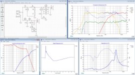
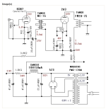
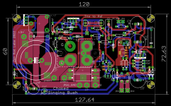
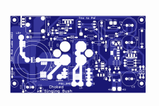
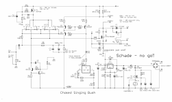
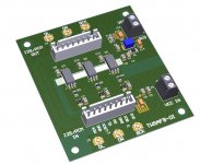
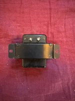
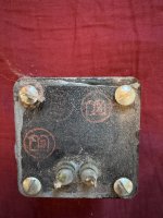
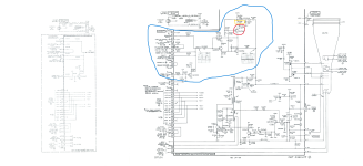
surface noise of the record. In my amp (using op amps with FET input, see attachment)
there are two inverting stages so that the first one is producing RIAA curve with
dc amplification of 40dB and the second one acting as a buffer giving extra
amplification of 20dB. It is well known that shunt feedback handles transients
better than series feedback and in my experience it can be heard too. In a way
shunt feedback concept is half passive by keeping the op amp out of the signal
path as much as possible.

...MK

Attachments

Building Class D integrated amp in vintage case

I want to build a class D amplifier to be integrated into a vintage case. I want to keep things simple, but not overly so. My knowledge of these things is limited, so forgive me in advance if I am being silly in any way.

Power supply
Should I (and can I) just use the existing vintage power supply?

If I decide to replace it, I would go for a switching power supply (ready-made PCB). I want to buy off the shelf high quality stuff - any resources you can point me to?

Digital crossover
There will be one digital signal input. I want a 4 channel output (mid and high freq, stereo). As with everything in this project, I want to buy off-the-shelf pcb boards, hopefully as high a quality as I can afford.

Do I need a DAC before the crossover? Or are there crossover designs that are purely digital?

I would like to buy a PCB board where I can tweak (mechanically?) the crossover frequency (inside the vintage box) and slope. Does this exist? I would then close the box and keep it closed until I change the speakers, for example. Or move to a different room. And then set the new crossover frequencies and slope if needed.

Where can I buy, and find resources on, these boards?

Power amplification
I am looking at two 2x100W stereo, or four 100W mono class D amplification.

Would I control the volume (through the existing knob on the vintage case) on the input to these two (or four) amps. Anything I should be aware of here?

Again, any resources or recommendations on where I can buy off the shelf PCB boards would be very helpful.

Speakers
Not strictly part of this project - but I would use my existing passive speakers, but with the crossover physically removed.


That is it, I guess. If there are any useful threads on the forum - I would appreciate any pointers. There is just so much material that I am getting lost.

Copper wire vs bananas vs mud - An interconnect test

Do you remember the great fun we had 11 years ago when I ran audio signals through fruits and vegetables, beer, coke, steel wool and other stuff? No? Not to worry, here is the banana mud redux!


Banana desktop.jpg


The idea of this blind test is that the same audio signals were run through copper wire, then through mud and then through bananas and recorded them. You get to listen to the files and figure out what differences you hear. It's good fun for all and you might be surprised by how each different material sounds. Have a listen, make some notes and let me know what you hear. Do Not post your results here (because spoilers) just send me a direct message with your findings.

In this these Google folder you will find the test files.
FLAC format. Lossless and faster downloads.
https://drive.google.com/drive/folders/1hxRL2L_M5O0fD8Ll9Y2dphqQgaeCKW_I?usp=sharing

And in WAV format if you can't deal with FLAC.
https://drive.google.com/drive/folders/1fe8-0kYWexOEveq5DPJ1zqPFP3RQZQ4S?usp=sharing

Pick a song or three that you like, and compare the versions. In those folders you will find many tracks arranged by musical genre. All tracks are 30 secs long. You should easily find something with which you can judge sound qualities. There is rock, jazz, classical and others - pick what you like and have a listen.
Remember, DO NOT post your results here, you don't want to bias the other listeners. Send me a private message. I will respond to your message and answer questions.

In the next post I will explain more about the test.

What is the most complex crossover you've implemented?

So I'm making these speakers. And I'm going for this Harsch XO style. And by the time I get it set up it's gotten a little crazy. And it makes me think let's talk about complex crossover designs.

XO and validation.jpg


AULA Spkr XO.jpg

Thank goodness for wagos!

But then I think - ya know? I bet someone on DIYAudio has something way crazier than this. I mean, you could make a passive 4-way, do it 4th order, that'll be like 10,000 components NP. But a complicated 2 way gets respect also, I think. Total complexity, or complexity per band. You know what I mean. But implemented designs only! "I designed something but then didn't build it b/c it was insane" doesn't count. And also, passive - anyone can put 45 biquads in DSP if they wanna. If you actually built something crazy, why did you feel like it was worth it to go the extra mile?

Also, I was thinking about the possibility to build something like this before electrical simulation and measurement software were as good as they are today. So I welcome discussion of crossover complexity today vs. back in history. And, hobbyists may choose to pursue designs that wouldn't make sense commercially, so discussion about commercial XO's vs hobbyist decisions WRT complexity and motivation are also on-topic.

Who has some interesting stories?

Attachments

  • XO and validation.jpg
    XO and validation.jpg
    266.9 KB · Views: 198
  • Like
Reactions: tubelectron and stv

Taramps DS 1200X4 2 ohms turns on but no audio

Hey! I've been working on this amp for awhile and at first I thought it was the IRS 2093M that was the issue, given the fact the the fan stopped working, so I thought the chip cooked itself.

Bought the chip on Digikey dropped it in same issue. Also there's this periodical pop sound when speakers are hooked up and you can just barely hear the audio prior to me changing out the chip. But I don't think there was voltage on the output before, there no 4.9 volts sitting on the output, so I took out the entire output stage, almost. Now there isn't any voltage.

Can anyone help?

Power supply is okay 53- and 53+ on the rails. There's also 14+ and 14- on the op-amps and the IRS 2093 chip also has its 2 14 volts supply and 5- and 5+ volts.

Attachments

  • IMG_20250113_172026.jpg
    IMG_20250113_172026.jpg
    235.6 KB · Views: 67
  • IMG_20250113_172046.jpg
    IMG_20250113_172046.jpg
    199.6 KB · Views: 57
  • IMG_20250113_172054.jpg
    IMG_20250113_172054.jpg
    256.5 KB · Views: 62
  • IMG_20250113_172339.jpg
    IMG_20250113_172339.jpg
    367.2 KB · Views: 65
  • IMG_20250113_172350.jpg
    IMG_20250113_172350.jpg
    393.9 KB · Views: 64
  • IMG_20250213_194759.jpg
    IMG_20250213_194759.jpg
    353.2 KB · Views: 61
  • IMG_20250213_200024.jpg
    IMG_20250213_200024.jpg
    326 KB · Views: 53
  • IMG_20250213_200108.jpg
    IMG_20250213_200108.jpg
    410.8 KB · Views: 59
  • IMG_20250214_144923.jpg
    IMG_20250214_144923.jpg
    448.5 KB · Views: 54
  • IMG_20250215_140315.jpg
    IMG_20250215_140315.jpg
    362.7 KB · Views: 55
  • IMG_20250216_122501.jpg
    IMG_20250216_122501.jpg
    340.7 KB · Views: 54

true ribbon - GRS vs Fountek

is the GRS:

https://www.parts-express.com/GRS-RT3.0-8-Hi-Res-Neo-Ribbon-Tweeter-8-Ohm-272-206?quantity=1

going to be as durable as Fountek ?

https://www.madisoundspeakerstore.c...lk-5-ribbon-tweeter-rectangular-flange-black/

are they both sandwich diaphragm ? it seems GRS is just aluminum. so it means it is fragile ?

what justifies the price discrepancy between the two ribbons ?

i would be blasting these with 130 decibel bass.

would they hold up ?

or at least one of them ?

i just want the cheapest true ribbon that won't break the second bass hits it, well, and also i want the ribbon element to be user replaceable.

i suppose that's the weakness of the fountek - that you can't make your own sandwich ribbon ? or can you ?

please educate me.

Single sheet TH challenge

Ok, so being 'never satisfied' I'm trying to better 'the cube' that I just built a few of.

Since there are several hornresp tapped horn quarterbacks that are better than I.... Here's the challenge.

1. Single 4x8 sheet of plywood. All panels, including bracing/reflectors, etc..
2. Most SPL 'area under the curve' from 40hz-140hz (minimum 100db average +-3db 1W1M)
3. Minimum 125db single cabinet from 'about' 40hz on up in 2pi space (understand, some designs in single cabinet won't 'quite' be able to hit 40hz, that's ok...)
4. Under $200 driver.

Bonus points for a better shape than a cube.

EDIT:

This section of the original post will be used for navigating this thread, and will be updated occasionally.
This sub was designed for the eminence series of drivers, 4015lf, 3015lf, Kappa Pro 15-LF2. Others work too.

cad drawing -- http://www.diyaudio.com/forums/subwoofers/170771-single-sheet-th-challenge-8.html#post2278081
General Layout -- http://www.diyaudio.com/forums/subwoofers/170771-single-sheet-th-challenge-6.html#post2273977
cut sheet -- http://www.diyaudio.com/forums/subwoofers/170771-single-sheet-th-challenge-4.html#post2265677
note about using PL premium poly glue -- http://www.diyaudio.com/forums/subwoofers/170771-single-sheet-th-challenge-49.html#post2484469
High pass filters and excursion -- http://www.diyaudio.com/forums/subwoofers/170771-single-sheet-th-challenge-74.html#post2509736
First thoughts on 'cone correction' -- http://www.diyaudio.com/forums/subwoofers/170771-single-sheet-th-challenge-60.html#post2499741
Directivity Testing -- http://www.diyaudio.com/forums/subwoofers/170771-single-sheet-th-challenge-85.html#post2525499
Non US driver, (monacor) -- http://www.diyaudio.com/forums/subwoofers/170771-single-sheet-th-challenge-113.html#post2759432
US Drivers/PowerRatings -- http://www.diyaudio.com/forums/subwoofers/170771-single-sheet-th-challenge-173.html#post3193764
Nice little comparison chart -- http://www.diyaudio.com/forums/subwoofers/170771-single-sheet-th-challenge-119.html#post2836328
One of my favorite pics of FlipC's dozen -- http://www.diyaudio.com/forums/subwoofers/170771-single-sheet-th-challenge-88.html#post2528082
Quick post about construction technique -- http://www.diyaudio.com/forums/subwoofers/170771-single-sheet-th-challenge-43.html#post2470384

Dayton SA1000 Subwoofer amp

SOLD!

Had this along time and it worked great powering a huge folded horn sub with two ID15 subs then later two sealed ID 15's then in our RV a single Arc Audio Black 12, all sounded great! Unfortunately I slipped when taking it down from a cabinet and one of the pots for tuning was bumped then it stopped working, sure that it just needs a solder joint or two fixed or the pot replaced. I have to many projects and not enough interested as not going to be able to use it to repair so selling as is.

Selling instead of fixing it because I need to go to D class for all my amps to save energy as preparing to go solar as soon as we can.

$99 plus shipping.

Rick

XSD drivers, 8" woofers instead of standard 6.5", both mids and tweeters as well

Updated 01 March

All the drivers for the great XSD speakers I ordered awhile back but came to the conclusion just not going to work out for my listening space, which I knew all along but was going to at least try them but not doing so now🙁

All drivers are new in box but opened one of each to look them over, never hooked them up.

Available:
18) GRS 8PR-8 8" woofers (16 requited, 2 are spares) $179 plus shipping, OBO
----------------------------
On Hold:
2) GRS PT2522-4 planar tweeters, $69 shipped!
----------------------------
SOLD, and shipped:
2) PVR 5MR450-NDY 5" Neo midrange


Thanks,
Rick

For Sale Bottlehead Quickie preamp with 36 each 3S4 vacuum tubes

This preamp was built by a DIY Audio member when I purchased it. Sale includes thirty six 3S4 vacuum tubes of various brands, most in their original boxes. If you're not familiar with tube rolling, this setup can help with that.

This preamp is powered by dry cell batteries. Two D-cell and four 9V batteries last about 150 hours.

Asking for $250.

IMG_2084.JPG


IMG_2082.JPG


IMG_2083.JPG

(naïve) Question about this phase inverter circuit

Hi folks,

I'm an happy owner of this 2x5881 PP and I'm asking myself looking at the schematics about the phase inverter part of the circuit.
As I see it, it looks like a long tail pair circuit, but I don't get how the gain is leveled between the 2 outputs.
Most of the time, the gain difference is leveled via plate resistors, but there are the same, and there is this weird thing going to the grid of the second tube.
Please light me up on this !
Cheers

Attachments

  • ampli-hifi-tubes.jpg
    ampli-hifi-tubes.jpg
    116.2 KB · Views: 170

When I connect the Harman Kardon AVR265 HDMI 1 to the TV, the AVR detects an Fide TV, but the Harman Kardon AVR265 tV does not give the screen a menu

Hello, harman kardon avr265 avr anfide detects the tv when I connect hdmi 1 to the TV, but harman kardonavr265 does not give a menu to the screen, I could not solve this problem, I do not know where to look, what to control, I would be very happy if you could help me.

Reasons for torroid overheating

Hi.

After 20+ years of tampering with electronics (and getting an EE), I burned my first torroidial transformer!

The issue is that I dont understand why... The setup is 2 identical transformers with primaries in parrallel and secondaries in series.
Its powering a active subwoofer (300-400W classD and in THAM10).
All voltages check out and the setup was working fine for hours with minimal heat.

After the initial test the sub was stored in the basement for a few months and when I took it out for a test one of the transformers started smoking and melted the insulation within 2 minutes. I tuned off power as soon as I detected the fault.
The other transformer appears to be fine. Pretty sure that there is not an overload from the amplifier.

After removing the transformer, it was clear that it had shifted slightly beacuse the mounting pads had also melted somewhat.
I can understand that heavy vibration and melting mounting pads is an recipe for disaster, but Im not sure on the root cause.

One possibility is that I did not thighten the mounting bolt enough. - or maybe too much? - but Im pretty sure both transformers were mounted OK.

Any ideas? how would you secure a torroidial used in a sub? I´ve seen in commercial subs, so I assume its acceptable.

Kind regards TroelsM

Tubelab TSE-II with 45 tubes- One fully functioning and one bare PCB

SOLD. Thank you


Included in this sale is one bare TSE-II pcb, and one fully built and functioning 45 tube amp built with a Tubelab TSE-II pcb. Includes one Silvertone 45 tube, one National Union 45 tube, two Raytheon JAN 5642 tubes, one RCA 5U4G, one TEMco CBB65-R Run Capacitor, one Triad C-14X transformer, two Electraprint output transformers, and one Hammond 270FX power transformer.

The working TSE-II pcb was assembled by me in 2020, prior to my retirement. I called Jack Eliano at the former Electraprint shop and asked him to sell me the two output transformers for a 45 tube amp. I think they were $120 each, 5K:8 Ohm. Also, having a now retired former accountant wife, I always had to hide the true cost of items I bought in order to stay within my budget. 😉

All tubes were tested with my formerly owned Hickok Tube Tester and tested as NOS for all tubes. The working amp was assembled, bias adjusted and sounded really nice. I have the receipts for all the components, the total was ~$105. A 5U4G tube is well over $150 from Tube Depot, and a good pair of 45 tubes ain't cheap. Neither are the 5642 tubes.

I am asking for $600, or best offer for everything shown here. What you see is what you get.

IMG_2061.JPG


IMG_2079.JPG


IMG_2075.JPG


IMG_2080.JPG


IMG_2070.JPG


IMG_2071.JPG

Old FANE driver

Hey guys,

I've visited an old Hifi buddy and listened to his new open baffle project with old Fane drivers. I liked the sound and would like to copy that project but the driver seems to be a phantom. I've searched the "whole internet" and couldn't find any information on this driver.. let alone a sales offer.
It's a 12" driver and I think it must be from the 70s (the man. date says something different but I think this is just the serial number)
Here are some pics:

PXL_20250207_151736357.jpg


PXL_20250207_151707948~2.jpg


I don't have a pic from the front but it has a whizzer cone.
Does anybody know anything about this driver? Especially where it was mounted? Guitar amps? Organs?

I really would love to rebuild the project so any help is highly appreciated!

Greetings
Tim

Lower My B+ Help

I built a clone fi SET amp last summer and I am primarily using 2A3 tubes. With Don’s original design one could use 2A3’s or 45’s but when using the 45’s you have to use a 5Y3 to lower the voltages. I’m using a 5U4GB with my 2A3’s safety within spec but when using the 45/5Y3 I’m at the hairy edge with the following numbers: plate voltage 237VDC, 47mA, plate disposition 11.3W. Is there an easy why to lower my B+ as to get in line with the 45 specs?

Choked Singing Bush ..... special one for Purists and Masochists

OK, this one long in making
I mean - have pcb files and everything for some time, basic functions confirmed but - as is my nature - never working by plan :rofl:

Anyway - why Purists and Masochists?

List of reasons:

1. you really need properly made high quality choke; 100mH, no more than 0R5 winding resistance, declared for 3A5dc (big Tokin) or 2A5dc (small Tokin)

2. PSU - bummer - heavy filtration; CLC, or C then cap multiplier followed with heacy C cell, or fat switcher ..... most likely also followed (by choice or necessity) with some sort of high-pass filter and followed with fat C cell

3. this time ( even if evidently intended as option) - no Schade Mos Puck; simply too high Rout of part itself (even if normally or even heavy Schaded), resulting in uberfunny transfer function and THD way too high; now - with all my crummy chokes (yes, Plethora of them but all crummy) that's the situation; there is a possibility that Schaded option is viable and worthy if adequate quality choke is used, but that I can't confirm, nor I intend to purchase it, in any way or arrangement

4. looking at all above - simply - cost; you gain something with lesser volts involved (vs. say "regular" Singing Bush) thus lesser heat and lesser Donut and lesser voltage caps and lesser Aluminum in sinks...... but then main choke, PSU choke, yadayada....

5. yes, OPT is an option, for both shown iteration ( Big Tokin, small Tokin), don't have it, easy to try if you have one; same conditions as with choke - do not even try with cheaply made Iron

there are few more reasons, worthy of this list, but I'm lazy to think now .....

Anyway, usual set of introductory eye-pleasing files:

Attachments

  • Choked Singing Bush Eagle sshot.png
    Choked Singing Bush Eagle sshot.png
    49.9 KB · Views: 1,252
  • Choked Singing Bush top render.png
    Choked Singing Bush top render.png
    1.1 MB · Views: 540
  • Choked Singing Bush bottom render.png
    Choked Singing Bush bottom render.png
    875.4 KB · Views: 1,222
  • Choked Singing Bush schmtc.png
    Choked Singing Bush schmtc.png
    352.8 KB · Views: 1,249

For Sale Keysight DSOX 1102G 2 channel 70 mHz 2 channel oscilloscope, built in Waveform Generator

Asking $500 including USA shipping. Payment by Zelle or Paypal. SOLD

I am the second owner of this Keysight oscilloscope. No functional problems that I have noted.

2 channel with built in function generator. Can easily do Bode plots.

Comes with the 2 standard probes as shown, a few extra cables, and a basic power cord.

No original packaging, but it will be carefully packed surrounded by rigid foam board.

I have the manual as a pdf I will send to the new owner.

USA shipping only.

IMG_1873.jpegIMG_1875.jpegIMG_1876.jpegIMG_1877.jpegIMG_1878.jpegIMG_1880.jpegIMG_1881.jpegIMG_1882.jpegIMG_1883.jpegIMG_1885.jpeg

The Well synchronized asynchronous FIFO buffer - Slaved I2S reclocker

Since the latch signal is crucial to get the best performance from a DAC we are developing a FIFO re-clocker that runs slave to the master clock.

In other words the FIFO buffer and re-clocker FPGA based does not manage the latch of the DAC (WS signal in I2S format and LLLR in PCM format) that comes directly from the master clock via a programmable divider isolated from the other digital circuits.
This to avoid any interference between the FPGA based digital circuit and the conversion circuit inside the DAC.

Every time the latch signal switches new data are asked to the FPGA, using all optical isolated lines.
This is a different approach in respect to other similar devices where the FPGA works on all I2S signals including the word select.

There will be 3 boards, the main FIFO re-clocker and the optional User Interface and Output Interface boards.

The main board has 4 I2S input selectable by the User Interface board.
Also the dithering process is selectable via the User Interface board.

There are 2 output options, both with header and u.fl connectors.
The main board needs 2 master clock signals, one for each sample rate family.
It can accommodate the Crystek or NDK oscillators, but a pair of very low phase noise are strongly suggested (5.6448 MHz up to 24.576 MHz).

More infos next days, a prototype is on the way.

New RPI Interface, LVDS transmitter and receiver I2S over HDMI from post #125
The Well synchronized asynchronous FIFO buffer - Slaved I2S reclocker

User manuals at post #153
The Well synchronized asynchronous FIFO buffer - Slaved I2S reclocker

Attachments

  • TWSAFB.jpg
    TWSAFB.jpg
    211.7 KB · Views: 3,689
  • TWSAFB-UI.jpg
    TWSAFB-UI.jpg
    146.3 KB · Views: 3,600
  • TWSAFB-OI.jpg
    TWSAFB-OI.jpg
    123.1 KB · Views: 3,551

Behringer CX2310 high noise levels, replace op amps?

Just got one of these and the noise levels are relatively high, its clearly audible from a few meters away with 85dB/1W/1M speakers. The original op amps are the 4580 as buffers and the 2060 for the filters, see partial schematic below. I have checked the power-supply to the op amps and its as clean as it gets with 7815/7915 regulators.
I am considering changing the 4580/2060 for the OPA165x Op Amps to get the noise levels down, any thoughts or other suggestions on this from anyone?
X-Pro schematic partial.JPG

For Sale Power Transformer, Filament Transformer, Chokes Hoard

I have the following power transformers, filament transformers, and chokes for sale. These were acquired over the years on eBay—some were used temporarily, while others remained unused.

I will add more items as I continue to sort through my collection.

Pricing: All prices are net to me. Please add shipping costs from Brooklyn, NY 11211, and 3% fees if paying via PayPal (as a purchase) or Venmo (as a purchase). No fees are required if paying via PayPal (as a friend), Venmo (as a friend), Zelle, or bank transfer.


Power Transformers:
  • Freed 29856 (Potted)
    750VCT @ 85mA, 5V @ 2A, 6.3V @ 2.75A
    Painted Black
    $40
  • Triad R-18A
    Primary: 115V
    Secondary: 750V CT @ 175mA, 6.3V CT @ 8A, 5V @ 3A
    $100
  • Triad R-116A (Full-wave)
    Primary: 117V
    Secondary: 700V CT @ 160mA, 6.3V @ 5A CT, 5V @ 3A
    Has scratches
    $50
  • Bendix Aviation L217151-1
    Plate Transformer
    $15


Chokes:

  • Freed 36856 (Potted)
    6H @ 85mA
    Painted Black
    $20
  • Tango 110
    10H @ 100mA
    $30
  • Sansui C-905
    10H @ 150mA
    $35
  • Bendix Aviation L217386-1 (Potted)
    10H @ 100ADC (or possibly 150ADC?)
    $15


Filament Transformers:

  • Standard Transformer P-3026
    Primary: 107-117V
    Secondary: 5V @ 3A CT
    $30
  • Peerless Electrical Pepco 1040
    6.3V
    $25
    I may still have the original box

Attachments

  • IMG_1642.jpeg
    IMG_1642.jpeg
    409.4 KB · Views: 50
  • IMG_1643.jpeg
    IMG_1643.jpeg
    369.9 KB · Views: 51
  • IMG_1644.jpeg
    IMG_1644.jpeg
    412.7 KB · Views: 49
  • IMG_1645.jpeg
    IMG_1645.jpeg
    345.2 KB · Views: 48
  • IMG_1646.jpeg
    IMG_1646.jpeg
    463.6 KB · Views: 46
  • IMG_1647.jpeg
    IMG_1647.jpeg
    383.5 KB · Views: 50
  • IMG_1648.jpeg
    IMG_1648.jpeg
    436.2 KB · Views: 55
  • IMG_1649.jpeg
    IMG_1649.jpeg
    444.2 KB · Views: 45
  • IMG_1650.jpeg
    IMG_1650.jpeg
    529.3 KB · Views: 46
  • IMG_1651.jpeg
    IMG_1651.jpeg
    546.4 KB · Views: 53
  • IMG_1652.jpeg
    IMG_1652.jpeg
    548.2 KB · Views: 51
  • IMG_1654.jpeg
    IMG_1654.jpeg
    467.6 KB · Views: 52
  • IMG_1655.jpeg
    IMG_1655.jpeg
    501 KB · Views: 47
  • IMG_1656.jpeg
    IMG_1656.jpeg
    582.9 KB · Views: 51
  • IMG_1657.jpeg
    IMG_1657.jpeg
    520 KB · Views: 42
  • IMG_1658.jpeg
    IMG_1658.jpeg
    430.4 KB · Views: 59
  • IMG_1659.jpeg
    IMG_1659.jpeg
    482.9 KB · Views: 43
  • IMG_1660.jpeg
    IMG_1660.jpeg
    852.2 KB · Views: 47
  • IMG_1661.jpeg
    IMG_1661.jpeg
    679 KB · Views: 51

Which system you would consider the best for specific genre of music ?

I did not found this topic so I hope it was not discussed somewhere, but I would like to know opinions (because this is what they are i am not trying to find the BEST) about from own experiences what system you would recommand for specific kind of music.
For example which speaker design for :

CLASSICAL CHAMBER MUSIC
BIG ORCHESTRA
JAZZ
BLUES
HEAVY METAL
PUNK ROCK/HARDCORE
POP
FOLK
LATIN
ELECTRO
HIPHOP
CHORUS

I tried to cover style by frequencies i am open to changes. Mono vs Stereo can also be in the answers, but it's not the main point. There will be a full rangef against multi way but even in multi way there will be sub genre as there is sub genre in music.

For example as my nickname suggest in this forum, I have been in love with listening to Time out Take five with caisson RJ from supravox. I will not state it is the best, but the overall listening experience is fantastic for me (this picture is not from me).

Time+Out-403762129.jpg
RJ.jpg
  • Like
Reactions: limono

End Game Array V2

messed up the title - it was supposed to say " please critique this " like the original thread.

it became obvious to me that i can completely eliminate one of 5 frequency bands from original design without much detriment so i did. here is the new design ( this is a horizontal cross section / view of array from the top ). the top of image is a waveguide that is forward facing towards the listener. the bottom of the image is a rear-firing subwoofer.

array sketch crop v2.jpg


for reference here is the original thread when the design was 5 way, which is embarrassing now because of how much more complex and expensive it was for almost no benefit:


but that thread has a lot of information about what i am trying to accomplish with that design so i am including a link to it.

basically all the drivers remain the same except that 12" woofers are eliminated. previously they covered 60 hz to 150 hz range but now the 18" subs simply go up to 120 hz and the 5" midbass array stretches a bit lower to 120 vs 150 hz.

there was originally a purpose to 12" woofers a few design iterations back but they lost their usefulness over several redesigns so now they're gone.

Some quick questions on Zen Decware EL84 SET schematic

I noticed I have all the parts to make this Zen Decware EL84/6BQ5/6P15P amp. I have a few quick questions about some possible improvements, opinions welcome. I want to make this a fast-build project so I'm not looking to depart too much or start all over from first-principles. Just what would be some good tweaks, if anyone wants to chime in. Schematic attached. Here are my questions:

1) Both the L/R output tubes are biased on the same cathode resistor, I assume its probably better for me to use two 75 ohom resistors instead of the single 150 ohm.

2) There doesnt seem to be a whole lot of capacitance in the reservoir and smoothing caps (only 33uf per). I have some 60uf motor run caps that I was thinking of using instead, go all-film since the designer didnt call for much capacitance in this design.

3) There seems to be a weird voltage divider dual capacitor decoupler (3.3 uf caps) for the 6N1P plates. What is that all about? I'll keep it I guess and I have some 5 uf motor run caps for these too.

4) The tranny voltage is 300-0-300 volts is this about right? does the operating point look ok overall at this voltage?

I'll be using this low-watts amp with a pair of Klipsch RP600M speakers (96db at 2.83V / 1m) and an 8 inch powered sub woofer coming off the speakers.

https://f072605def1c9a5ef179-a0bc3f...product-specsheets/RP-600M_Spec-Sheet_v01.pdf

Attachments

Crossover Recommendations for a Small Subwoofer

Hello,
I have two Tectonic TEBM65C20F-8 3-1/2" BMR Full-Range Speaker 8 Ohm speakers I want to supplement with a Tang Band W5-1138SMF 5-1/4" Paper Cone Subwoofer Speaker to add more bass response. I plan to put all three in a three chambered enclosure for use in a bedroom/office setting. I'm looking for a suitable preassembled crossover that will work for this pairing. I would like the crossover frequency to be around 200 Hz - 300 Hz based on the various speaker specs and modeling curves. The FR speakers are 8 Ohm, and the subwoofer is 4 Ohm.

I'm considering using a Parts Express 100 Hz Low Pass 8 Ohm Crossover Part #266-446. This is an 8 Ohm crossover. If I use two of these crossovers with that subwoofer (one for each FR speaker), can I reasonably expect the crossover frequency to increase from 100 Hz to somewhere near my desired 200-300 Hz? Are there any concerns to consider about doing this?

Recommendations for something else to consider are appreciated.

Thanks.

100 Hz Crossover
TEBM65C20F-8
W5-1138SMF

SMPS Noise and Ground Loop Issues with JLH Amplifier – Need Filter Advice

Hi everyone,

I am building a 4-channel JLH amplifier powered by a 24V Meanwell LRS-150-24 SMPS for a FAST system (2x SB34NRX75-6 woofers and 2x 4-inch full-range speakers). However, I am experiencing high-frequency switching noise and ground loop issues.

While searching for solutions, I came across two different SMPS DC filters on DIYAudio:

  1. ACA Power Supply Filter
  2. PO89ZB Filter
I noticed that these two filters use very different inductor values. One has 2.2µH, while the other uses 180µH. I’m trying to understand why there is such a big difference and which one would be more suitable for my JLH amplifiers.

I also have 10pcs of white and yellow toroidal cores that, as I recall, produce 100µH with 22 turns. Can I use these for an SMPS DC filter? Additionally, I have some 27µH (13x13mm green) inductors.

Would these components be useful for reducing switching noise and ground loop issues? I also have many different capacitors to make pi filters.Any advice, filter schematics, or suggestions would be greatly appreciated!

Thanks in advance!

Attachments

  • 20250228_233032.jpg
    20250228_233032.jpg
    654.3 KB · Views: 60
  • 20250228_232811.jpg
    20250228_232811.jpg
    462.7 KB · Views: 61

Paper capacitors?

I got 10 of these 5nF capacitors very cheap:
capacitor.jpg

It says 'DIN41161' and if I look that up I see it is a 'paper capacitor'.
They must be very old, however the first two measure ok, didn't check them all. And they do not seem to be used.
Are they still usable for audio? How is the quality of a paper capacitor compared to say, a film capacitor?

Tweaking sound Funkey RP-88A Rollpiano

A little tweak to a mobile electric piano brings a better sound to it:

The small loudspeaker got some papercone treatment with thin silicone sealant omitting the dustcap.

One ohm put in line made it sound less aggressive and more pleasing (adding a little bit of current drive to the amplifier)

The sound got much nicer and more articulate!

images-12.jpeg


IMG_20250228_073432.jpg


IMG_20250228_073254.jpg


Disassembling is easy only remove six screws.

loudspeaker is easy removable

And put all back again after tuning / tweaking the electric piano.

Here some fotos of the inside electronics

IMG_20250228_073403.jpg


IMG_20250228_073351.jpg

IMG_20250228_073307.jpg

Turntable Pioneer revisioned

good morning, I was given an old Pioneer turntable, on which I replaced the belt, cartridge/stylus (I put an AT VM95H) and created an external power supply. I would need documentation with clear suggestions to do best complete setup of it: set height, cartridge/stylus alignment etc... Furthermore, I would need a sheet drawn with the stroboscope, that I can download and print 1/1 to place it on the plate for turns number adjust . I apologize in advance if the topic has already been discussed, but I haven't found anything yet (if so, can you provide me with the link). Thank you. Kind regards and the entire forum. Ros

GRS vs Fountek vs Aurum Cantus vs RAAL

first off i have never heard a ribbon tweeter in my life so this is just my take based on research i was able to do online and i may be wrong, but this is what it looks like to me:

GRS: seems to be fake Fountek, or at least an el cheapo version of it - probably made in the same factory, but with smaller magnets and regular aluminum ribbon ( not sandwich ). the foil is also very thick. efficiency is low for a pure aluminum ribbon.

Fountek: decent ribbon but spotty availability and it is more than a little bit concerning that manufacturer doesn't even have a website. the housing is made of plastic such that for example the front bezel screws into plastic and the "fins" on top and bottom that hold the ribbon also attach to plastic. not very nice.

i feel like the cheap plastic build of Fountek is appropriate at GRS price point ( which uses the same build ) but not at Fountek's price point. you do get bigger magnets in Fountek and it is unclear what kind of ribbon element you get.

Aurum Cantus: 50% heavier than Fountek because it uses no plastic and magnetic return structure is cast iron, not stamped steel. also because plastic is eliminated it has smaller exterior dimensions for same ribbon size, which is beneficial for line arrays maintaining tighter gaps between ribbons. 100db effcient. replacement ribbons sold through PE.

RAAL: very fancy and expensive. you can buy an entire GRS driver for the price of RAAL replacement ribbon. made in Europe. all the other ribbons mentioned above are made in China.

to me personally i think Aurum Cantus is the sweet spot. all metal construction and cheap replacement ribbons.

but ironically Aurum Cantus seems to be the least talked about out of the four ... any ideas why ?

Tektronix 577 D1 curve tracer intensity malfunction

Hi and thank you for the forum!
I bought this equipment a week ago and it was quite OK when I did resistor, capacitor and diode measurement (user manual). anyway, it didn't go so well when you wanted to check the characteristics of a transistor.
I decided to go through the calibration according to the service manual and this is where I ran into problems. I tried doing point 4 "adjust intensity range" INT RANGE potentiometer (R1245) rotated sluggishly so I sprayed it with some electric lubricant (see picture) then when I started again, the intensity knob no longer worked. I checked the service manual again and drawing 8 (see attached picture) and discovered that the resistor R1236 had browned. I changed it and then this browned again. I did ohm measurement on R1245 mounted on PCB and it varies between 0 and 1Mohm so I don't think the problem lies here. I suspect that it lies in the Z-Axis amplifier and the part that ensures that there is a constant current flow throw this operational amp. In other words, I suspect that C1236 or Q1234 are the culprits. What do you think? any advice can be of great help. It is quite difficult to pick out the whole CRT Circuit PCB and don't want to do it unless absolutely is necessary.
Another solution that I wanted to try is to isolate the board from all the remaining parts and apply power only to the yellow part of the drawing (External +30, -30VDC and 200VDC) via P1130, then inject a square wave (20Vp-p) on the anode part of CR1209 and see what the OSC have to say in the collector part of Q1226 if it looks like on the graph. What do you think? Transformer T1240 is powerless so there shouldn't be a mega-voltage out to the CRT (-3450V) right?
thanks!

Attachments

  • 2-26.jpg
    2-26.jpg
    52.3 KB · Views: 86
  • Intensity malfunction_1.png
    Intensity malfunction_1.png
    848.6 KB · Views: 78
  • thumbnail_IMG_6902.jpg
    thumbnail_IMG_6902.jpg
    58.4 KB · Views: 81

Is this a case of noise or oscillation? How critical is the impact of this signal anomaly

Greetings! I am building a GFA-565 amplifier, and the signal shown in the image is present at the amplifier's output. How much of an issue could this be for sound quality? Is it worth addressing this problem? Note that the amplifier is not yet installed in its case. The oscilloscope is set to 0.2 µs/div, 50 mV/div, and x1 probe position. The signal at the amplifier's output is approximately 20 MHz with an amplitude of 50 mV.

Attachments

  • Osc1.jpg
    Osc1.jpg
    118.5 KB · Views: 138

For Sale Hashimoto PT-150F power trans., HC-203U 2.5K/3.5K SE OPT pair

Hi all,

Hashimoto transformers, brand new and unused.

1x PT-150F power transformer:
Pri: 120V
Sec:
  • 280V-250V-220V-0V-220V-250V-280V-160mA AC (220mA DC: double wave rectification)
  • 0V-6.3V-2A (3 circuits)
  • 0V-5V-3A

HC-203U pair
Output: 20W at 50Hz
Primary: 2.5K or 3.5K Ohms
Secondary: 4, 8, 16 Ohms
FR(+-2dB) 30-60,000Hz
Suitable for 300B, EL-34, 2A3, 6GB4, 6L6-GC, 6A3


Asking $720 shipped CONUS. (roughly 10-15% off cost of new price)

Attachments

  • P1040772.jpg
    P1040772.jpg
    269.9 KB · Views: 75
  • P1040773.jpg
    P1040773.jpg
    235.4 KB · Views: 76

Dayton Audio CE32A-4 (1-1/4" Mini Speaker, 4 Ohm)

I installed the Dayton Audio CE32A-4 in a mini-sized bass reflex enclosure.
The finish is vinyl sheet.

HB-02F-01.jpg


It doesn't produce low frequencies, but it delivers a lovely female vocal performance.
Truly the "Songstress of the Dwarf Kingdom."
It may not be considered a full-range speaker, but it is sufficient to enjoy on its own.

Login to view embedded media

Attachments

  • HB-02F-03.jpg
    HB-02F-03.jpg
    172.4 KB · Views: 245
  • HB-02F-05.jpg
    HB-02F-05.jpg
    155.1 KB · Views: 245
  • HB-02F-04.jpg
    HB-02F-04.jpg
    185.5 KB · Views: 244
  • HB-02F-06.jpg
    HB-02F-06.jpg
    174 KB · Views: 291
  • HB-02F-07.jpg
    HB-02F-07.jpg
    195 KB · Views: 428

For Sale I2SoverUSB v.III and oscillator board and crystek clocks

Jlsounds I2SoverUSB v.III board
Oscillator board with crystek CCHD-957-25-45.1584 and CCHD-957-25-49.152 oscillators
And I have a couple power supply boards that go with it. 5V and a 4.2V made with LM317 and LM1117. You will just need to supply 7-12VAC input power.

I soldered a 9 pin molex header onto H3 on the oscillator board so you can connect to the I2S pins.

$100. you pay shipping.


SOLD


IMG_1529.jpgIMG_1524.jpgIMG_1525.jpgIMG_1526.jpgIMG_1527.jpg

For Sale XMOS XU316 multi channel audio development board XK-Audio-316-MC-AB

SOLD
XU316 XCore™ Audio Processing Audio Evaluation Board

Used to develop my own custom board around the xu316 processor. The board is in good working condition and is loaded with the default XMOS USB audio software version 8.1.0 USB audio 2 channel demo code. This the multi channel audio dev board, and you can develop your own application with up to 8 channels working simultaneously, or just 2. The board features 4 stereo DACs, a USB interface, and flexible clocking options.

U26 clock generator chip has been replaced with a pre-programmed version of the same part (Si5351A-B04486-GT). Otherwise everything on the board is stock.

Includes 1 USB micro cable.

$100 includes shipping to anywhere in the US

IMG_1238.JPG

Attachments

  • IMG_1239.JPG
    IMG_1239.JPG
    337.1 KB · Views: 42
  • MFG_XK-AUDIO-316-MC-AB.jpg
    MFG_XK-AUDIO-316-MC-AB.jpg
    70.1 KB · Views: 47

Proline 3000 Speaker Membrane Slow Return Issue (First Repair Attempt)

Hi everyone,

I have a T.Amo Proline 3000 amplifier, and I’ve noticed something strange when playing music. After every bass kick, the speaker membrane doesn’t return to the neutral position immediately—instead, it slowly moves back as if there’s some kind of delay. It’s not exactly a DC offset (at least I’m not sure), but the speaker doesn’t behave normally and seems sluggish in response.

I tested the same speaker with a different amplifier, and the issue does not occur, so I’m sure the problem is within the Proline 3000.

This is my first time attempting a repair, so I would really appreciate some detailed guidance on where to start troubleshooting. If possible, please explain things in as much detail as you can so I don’t miss anything important.

What could be causing this issue? Could it be DC offset, bad capacitors, or something in the power supply? How can I test for these things? Any help would be greatly appreciated!

I only have a Multimeter to work with.

Thanks in advance! 😊

Kicker IX1000.1 Distorted Audio

I had a Kicker which had a 15V regulator resistor blown apart. R173, R174, R176 are also all open/cracked.

It can drive a lot of power, but its heavily distorted unless I turn the volume mostly down.

What is weird is when bending/twisting on the board i could make it produce a very loud hash noise, and then sometimes it would come out perfectly clean with no faults in the audio.

So, from what I learned on the CX600.1 I went ahead and resoldered the whole power output stage. No change in behavior. I decided to inductance check and ring check both output inductors, and they match.

The fact I can bang on the PCB and get the behavior to change (sometimes) leads me to believe theres an intermittent connection somewhere but im just not finding it. its hard to track down the search area without a schematic.

Posted a screenshot of the output from the amplifier, that is supposed to be a sinewave but as you can see, its anything but. All 4 output transistors have a PWM drive waveform.
1740185798600.png

Wee bit of help identifying what caps are what

Looking for a little basic help. I have a tube amp that needs biasing. In order to do so I gotta get right in there. The amp is also about 10 years old and I kinda wanted to look around at the electrolytics and at least understand them in case they need changing at some point soon.

I have labelled the caps and my guess as to what they are. No schematic possible.

Hoping people can help me determine best guess as to what cap is what, especially filter caps so I can be extra careful.

I do have a discharge tool and understand basic safety and will be careful.

Any help is much appreciated

1. 2 x 470uf 450v (power supply?)
2. 1 x 220uf 450 (??)
3. 2 x 0.47uf 630 (output coupling?)
4. 2 x 47uf 450 (ps filter?)
5. 2 x 220uf 16 (input coupling?)
6. Some caps on a PCB that I could quite see and have no idea...
7. 2 x 220uf 63v (no idea?)

Attachments

  • IMG_20250228_163410.jpg
    IMG_20250228_163410.jpg
    53.3 KB · Views: 75

ML Folded Voigt Pipes ( ML TQWP or similar) construction design!

So, I know a lot has been said about this type of box, Good and Bad… and not all of that has been “ scientifically “ tested… (“ my mate told me this, so it must be true stuff”….)

So, I’m a “nobody, but I’ve built 11 boxes in a short time and I’m usually comparing the last 3 boxes that I make against each other to see if there’s progress ( some will say that I’m wasting my time) ( I keep 3 pairs of drivers so I can do comparisons with box construction,….yer I know audio isn’t an exact science)…

So, in my journey ( no, I don’t spend time with Horns rep), but, I started with “ Nandappe’s”design and I’ve been letting my ears and those of others guide my journey…
Yer, I can hear all the Computer warriors 🤡 crying, but it’s my gear in my room… I don’t expect a Computer program to fine tune that journey..

So, perhaps stupidly, I follow the ideas of Janos from “ Real World Audio “ You tube who says “ build it like a musical 🎶 instrument “, so my construction is much more like a guitar 🎸 top, than an MDF box..( MDF is Hateful stuff)..

Included in that idea is the finish that you give the timber..
A musician friend of mine suggested that timber oil sounds much nicer than varnish… and probably it does..
However I can physically feel a lot of vibration/ energy escaping through through the top of the box. ( yes it does have some stuffing there).
So, that leads me to think 🤔 that a straight pipe with a restricted mouth/ port might give me a purer midrange, but still keeping the bass balance…
Or maybe 🤔 I don’t need to, as the Midrange energy on a straight pipe would just bounce of the back wall instead of being released from the top of the box….

Ideas from people who have actually tried this stuff welcome 🤗 😊!!

Kicker KX2500.1 audible hiss

I have a KX2500.1 that was completely blown up so I rebuilt it. I noticed though with no input, theres a strong audible hiss from the speaker. like a waterfall. (This speaker is full-range btw).

I have not had this before when working on these amps, I removed the pre-amp board and no more hiss. So the problem is in the preamp.

I replaced both TL074C chips but the noise is still the same, not sure what's going on there.

I suppose the good news is, I can finger the LM13600 and listen to the radio station across the street :-D

Short of replacing the LM13600, I am not sure where to go with it. I did scope the output of OUT, and I can see the noise. it looks like an oscillation of around 13Mhz bursts repeating.

Tube newbie

Hi
I'm an electronics engineer that first got into electronics via the guitar. I built my first amplifier and took it to a job interview to show them what I'd made. I was 17 and got the job.
I went on to work in lots of different electronics fields including pro audio.
Fast forward 30yr and I'm interested in tubes to go with my terrible guitar skills.

Hello from Australia. I need your help with my Z5500 speakers

Greetings from Australia! I'm so glad to see so many others have enjoyed these speakers, looking at some of the threads here.. I've had my set for well over 10 years and have only just started experiencing an issue with them. figured I'd try my luck here. They turn on fine from the control pod but after a minute or two, the sound stops and the screen on the control pod goes mostly black (the blue led still is on). I have to turn the sub power switch off and back on and theyll work again for about the same amount of time. I did some research and found the easiest possible fix is replacing the fuse in the back. I went and got an identical fuse from Jaycar audio and replaced with but the same issue persists! i couldnt see this specific problem in any of the searches ive done but was hoping for some help on potentially fixing without needing to get too crazy and replace or bypass the control pod. thanks!

Hacking the Logitech Z5500

Like others on the net, I had something wrong with my Z5500 so they asked me to send back the controller and I ended up with an operational system and a "headless" one.

I now need a sub for a small system, and I figured I could somehow hack my Z5500 amp/sub for the purpose. After reading someone's post on how easy it was to access ins/outs and power switching on a 680 kit, since the connections had identifiable names on the PC board (FR, FL, RR, RL, etc...), I decided to take a look at the innards of the 5500.

After poking around in both the sub and the controller, I have to admit that there's a good reason Logitech asks for only the controller back: they've done everything possible to make it difficult for the DIYer to hack this speaker! Some of this stuff includes:

-No recognizable identification of any of the wire connections.
-Use of hot glue on the pcbs over many connection areas.
-Sanding of chip tops to prevent identification (mind you, the chinese subcontractor did a lousy job of this on my unit 😉 )
-The volume wheel on the controller seems impossible to take off. It feels glued (!). You can't clearly see the other side without removing it.

There's two main boards in the sub unit, possibly multi-layered: a preamp (5*4850's there) and the amp board with 8 heat sinked chips (7 chip amps + probably a regulator), but there's also some logic switching on the preamp board, probably responsible for turning on the amp. It doesn't look like it's a simple "switch-to-ground-to-turn-on" deal.

So in brief, it's not at all clear how to handle this. I may have to disassemble the amp board to see what chips are used, and just plug a diy preamp into the sub amp chips, bypassing everything else. I'll keep digging.

BTW, does anyone know a good way of removing this type of glue without damaging pcb and components?

I'm curious to hear from anyone else attempting/considering this.

ACA - help needed

Hi all!

Just finished building this amp and have issues with one channel not working. Once turned on, it just "farts" on the speaker, sounds like a 3 second discgarge noise for the lack of better explanation.

I've removed that channel out of the chassis and tested again isolated, same issue. All components check out measure vise (resistors and caps). Placement is exact as on the working channel. Did the resistance messurements suggested by the manual and here are the results (output connected, input and PSU disconnected):

Q1 -- S = 0, D = 4.96 k, G = 1 k
Q2 -- S=4.96 k, D = 1 k, G = 11.1 k
Q3 -- B = 5.65 k, C = 10.9 k, E = 4.96 k
Q4 -- S = 990, D = 1 k, G = 334 k

Is there any doc that shows how to test for correct voltages? Any help is greatly appreciated!

Thanks!!

REW FSAF revisited

Following @DcibeL post about using FSAF measurements across an Rsense of 0.1 Ohm, i open this thread.


First challenge was to find the latest Rew Beta, finally succeeded (only this morning), now i have to get into understanding the set up of Rew in combination with a RME Babyface pro FS.
Somehow my logic and that of Rew do not match very well yet, iow i have difficulty in getting it set up and calibrated.

But my checklist, once it is working, is to check the noise(or garbage ?) not only for drivers but also for the connecting cables.
  • Like
Reactions: TNT

Blown Sundown Salt 8 Amplifier

Hello ! I am working on fixing a blown salt 8 amplifier it looks as though one of the output fets died and took the output section along with the power section with it. I have repaired a few amps before but am no way an expert but do have the desire to learn more and get better at amp repairs. Ive established that the power section mosfets are IRF7530's but I do not know what the driver NPN/PNP transistors are, also the output section uses 24N40F's I was wondering would it be possible/ worth it to replace them with 24N50F's so the amp can handle charging in the 15v range a bit better ? From my understanding these SALT amps run very close to the output fet breakdown voltage when charging above 14.4-14.8 which leads to issues sometimes when charging any higher. Also what are the 5pin output driver chips there seems to be 4 of them directly in from of the driver card, rumor is they are all TC4452's but I just wanted to confirm. If these are blown is there a high chance it took the driver card with it as well? Any help would be greatly appreciated, I may ask alot of questions but I am trying to learn for future projects.
20230818_213930.jpg
20230818_234020.jpg
20230818_234012.jpg
IMG_20230828_161739_073.jpg

Luxman SQ38u

I recently purchased a Luxman SQ38u amp used. Seller stated that it's a 120v amp. I found out, while it was being shipped to me, that Luxman does not make a 120v version. The SQ38 transformer can be switched from 100v to 115v by Luxman for either market. This has led me to believe that the seller buys 100v versions and switches them himself misstating the voltage for the market he sells to.

To make a long story short, I can't tell if he actually did it and I am afraid the amp is working too hard at 120v. I can hear some buzzing from the power transformer, but also, a hum through the headphone jack that is very noticeable. Does anyone know how to check a transformer for it's operating voltage and the reason for the loud hum through the headphones?

Thanks!!

For Sale Clarity Cap MR (400V) capacitors, Solen capacitors

Hello all,

Purging some capacitors. All are used. All are roughly 50% of retail and include shipping and paypal in USA/Canada. All have leads that are roughly 1.25 inches (32 mm) long minimum.

Clarity MR 3.9uf (2) - $20 each
Clarity MR 15uf (4) - $30 each
Clarity MR 20uf (4) - $43 each

Solen 12uf (4) = $16 entire lot.

Thanks for looking!

Best,
Anand.

Edit: ALL CAPS SOLD!

Attachments

  • IMG_1055.jpeg
    IMG_1055.jpeg
    602.5 KB · Views: 111
  • IMG_1054.jpeg
    IMG_1054.jpeg
    625 KB · Views: 103
  • IMG_1053.jpeg
    IMG_1053.jpeg
    515.2 KB · Views: 107
  • IMG_1057.jpeg
    IMG_1057.jpeg
    620.2 KB · Views: 111

A Stereo 6N6P Hybrid Line stage w/Parafeed Output Transformer

What it is:
A single tube hybrid parafeed line stage using a single 6N6P - should work with the 6H30 as well utilizing Lundahl LL1930. This is not intended to be an ultimate design, but a cost effective design with transformer.

Each channel comprises half the 6N6P, a cascode CCS using DN2540 or similar, the transformer and a DC blocking capacitor. LED bias is used. Resistors are 1206 or 2512 SMDs.

There are two options for connecting the transformer; jumper configurable; one is directly to the plate of the 6N6P, the other is to the source of the lower device in the cascode. The LL1930 expects to see a source impedance of 4.5K or so and provision is present for padding resistors to satisfy that requirement. (There is obviously a small loss in gain.)

Gain is approximately 8 - 9dB
Frequency response 20 - 30khz @ 1dB or better
Output impedance should be < 150 ohms typical.

Distortion is predicted at 0.3% at 2Vrms out and is predominantly 2nd with 3rd about 20dB further down, not betting that is an accurate prediction. [Edit: This was way off, THD is typically 0.006% or less]

Both balanced and unbalanced output is possible, input is unbalanced only and is intended for connection to a 50 or 100K pot or stepped attenuator. I will be using a 50K stepped attenuator of dubious origins. (read inexpensive)

I've completed the design, but have not built or tested it yet, that's next.

Power supply will likely be unregulated and lightly filtered since the PSRR will be reasonably high. I will design that next.

Power transformer is an open guess at this point, raw DC voltages in the range of 230 - 300VDC are required. Filament power may/may not be AC, proximity to sensitive circuitry may drive the use of a cheap monolithic regulator for the filament supply.

I ordered the PCB from JLCPCB tonight and will order the rest of the parts (DigiKey) in the next few days.

The name is a bit of an inside joke, I recently designed a line stage using some left over discrete jfet input op-amps I designed which uses a heavily filtered dc to dc converter for power and is very compact. I called it the Cheesy Line Stage because it was supposed to be cheap. (It really wasn't) Trying to keep entertained in these times so I am doing cheesy line stage designs, the last was solid state, this one will be hybrid. After this I will move on and do something else.

Attachments

  • schematic.png
    schematic.png
    24.6 KB · Views: 2,571
  • Parafeed line stage V1.0.pdf
    Parafeed line stage V1.0.pdf
    55.2 KB · Views: 538
  • Topside.png
    Topside.png
    97.4 KB · Views: 2,383
  • 1930.pdf
    1930.pdf
    148.8 KB · Views: 405
  • 20211001_191839.jpg
    20211001_191839.jpg
    669 KB · Views: 2,226

Did anyone try one of these ES9028/ES9038 DAC kits?

Hi,

I am considering building a DAC and think these from DIYINHK based on ES9028PRO or ES9038PRO look interesting:

ES9028PRO ES9018 32bit Audio DAC PCB - DIYINHK

ES9038PRO XMOS DSD DXD 768kHz USB DAC with Bit-perfect volume control and SPDIF input - DIYINHK

Did anyone ever build and/or listen to one of these? Any experiences to share?

Thanks in advance,
Maartn

Changing QUAD 405 Input Impedance

Hello all, this may be a shot in the dark but i have read some excellent threads here so i know there are some well informed and experienced folk around !

I have a Quad 405 (mk1) which was modded some moons ago by a gentlemen named Ivan who was residing in London at the time.
Unfortunately i cannot remember what mods i had done exactly, but i do know it has dual power supplies* and rca inputs added.
(I've added pictures of the internals of the amp to this post)
Unfortunately i lost contact with him and have been unable to locate him.

I am going to try and use a potentiometer (alternatively named a passive preamp) inbetween my audio interface's DAC and my Quad 405.
The audio interface is a Fireface800 and the Output Impedance is 75 ohm.
So going by the rule of 20x, i am going to use a potentiometer at 1500 ohm, and then multiply that by 20 for the Quad = 30,000.
I believe the Quad 405's original Input Impedance is 20,000k, and i would be ok with that, however Ivan informed me back then that he added a resistor to the Input Attenuator which brought the Quad's Input Impedance down to 6800k.
(ah, i've just remembered that the Quad's Input Sensitivity was adjusted to 1.5v)

So my question is, can i simply remove this resistor in hopes of returning it to 20k, or does it involve making other adjustments ?
Or maybe even -can i increase this amount to 30k without complex work.
I am not proficient at circuits and electronics, but i am competent and experienced with soldering and getting simpler tasks done.

Any input at all would be most appreciated, thank you !

20250226_163456.jpg
20250226_163503.jpg

20250226_163511.jpg
20250226_163525.jpg

20250226_163557.jpg

20250226_163628.jpg
20250226_163650.jpg
20250226_163747.jpg

20250226_163804.jpg
20250226_163825.jpg
20250226_163853.jpg
20250226_163931.jpg
Projects by fanatics, for fanatics
Get answers and advice for everyone wanting to learn the art of audio.
Join the Community
508,492
Members
7,921,930
Messages

Filter

Forum Statistics

Threads
407,874
Messages
7,921,930
Members
508,492
Latest member
Stevejeanes