Looking for a little basic help. I have a tube amp that needs biasing. In order to do so I gotta get right in there. The amp is also about 10 years old and I kinda wanted to look around at the electrolytics and at least understand them in case they need changing at some point soon.
I have labelled the caps and my guess as to what they are. No schematic possible.
Hoping people can help me determine best guess as to what cap is what, especially filter caps so I can be extra careful.
I do have a discharge tool and understand basic safety and will be careful.
Any help is much appreciated
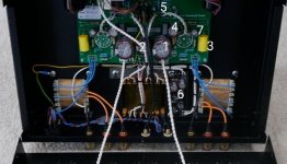
1. 2 x 470uf 450v (power supply?)
2. 1 x 220uf 450 (??)
3. 2 x 0.47uf 630 (output coupling?)
4. 2 x 47uf 450 (ps filter?)
5. 2 x 220uf 16 (input coupling?)
6. Some caps on a PCB that I could quite see and have no idea...
7. 2 x 220uf 63v (no idea?)
I have labelled the caps and my guess as to what they are. No schematic possible.
Hoping people can help me determine best guess as to what cap is what, especially filter caps so I can be extra careful.
I do have a discharge tool and understand basic safety and will be careful.
Any help is much appreciated
1. 2 x 470uf 450v (power supply?)
2. 1 x 220uf 450 (??)
3. 2 x 0.47uf 630 (output coupling?)
4. 2 x 47uf 450 (ps filter?)
5. 2 x 220uf 16 (input coupling?)
6. Some caps on a PCB that I could quite see and have no idea...
7. 2 x 220uf 63v (no idea?)
Attachments
Ten years is not that much unless amp was used 24/7, or incompetently designed.
If the amp works ok, best to leave it alone.
If the amp works ok, best to leave it alone.
I don't see any bias pots, but then it's hard to see so small a pic. What amp is it? Looks like a little single ended amplifier of some sort.I have a tube amp that needs biasing
jeff
It's a lab12 Suono, single ended.
Bias pots are just below the 6. I agree, best pic I could work with.
I agree, the caps don't need changing now from what I can tell, but having just had to recap about 100 caps in an active crossover (which fixed the issue)I would like to know what I'm dealing with if/when a problem arises.
Knowing which is the filter caps seems to just make sense having to be in there to bias anyway...
I have a basic understanding of what the different caps do, but not how to identify which is which.
I think most of your cap assumptions are more or less correct. The low voltage caps could be for cathode bypass duty.
Pretty tough to nail all of them without a schematic.
jeff
Pretty tough to nail all of them without a schematic.
jeff
Last edited:
