Pure Audio Project Thrier Crossover

I recently added an official Thrier crossover from PAP to my DIY Trio Open Baffles, running with 2x15” woofers and one 8” full ranger on each side. The original owner had used an active crossover and biamped them, but I bought the passive crossovers as these still seem interesting adaptable and keep me from needing to buy a new amp.

Anyway, I’m wondering if anyone has experience with this type of crossover and what kind of circuit it is I’m looking at. I’m wanting to experiment with different full range drivers, but am stuck thinking through how to calculate different crossover values as I don’t really know what I’m looking at. I’ve got the Tang Band W8-1808’s they came with, but also a pair of Lii Audio Fast 8’s and could out my hands on some Lowthers and Voxativs at some point. Should be fun!

Thanks for any tips. I’m guessing others have already blazed a trail here and I can coast in their wake...

Miller & Kreisel S-1B satellite crossover update

I have a mint pair of MK S-1B's that sound great. But I wonder if updating the caps will offer any improvement and figured I would see if anyone here has experience. Mine have the Peerless dome tweeters. I did find another thread on AK where the owner pulled the crossovers. The caps are small and easy to get to, but there were comments about the position of the inductors (there are 4).

What I'm hoping to get is some experienced advice on how to chose caps that will be an improvement. I've seen so many opinions on types of caps that I want to avoid getting into a roller coaster of "rolling" caps until I find the right ones, which would take awhile, but also open up the possibility of reaming the threads on the panel fasteners by repeatedly opening up the speakers.

I'm not looking for esoteric options, but something that is a known quantity.

Attachments

  • MK_S-1B.JPG
    MK_S-1B.JPG
    835.5 KB · Views: 545

Improving JAMO D265 C speakers on the cheap

Hello everyone!

I am thinking if someone could help me on my project - Upgrading a pair of Jamo D 265 C speakers on the cheap! While I know you can’t make a cheap speaker great, certainly we could make these better without spending a fortune, all while learning something along the way. Isn’t that the spirit of DIY? 😉

The speakers are Danish made, vented box with a 12” bass driver, a 5” (or so about) midrange and then a tweeter which I ain’t familiar with yet. The speaker box itself is made out of particle board with a decent thickness. But it has no bracing and very minimal damping. Also the bass / mid are quite badly fastened to the box, using plastic rings to compress driver to the box, without any sealing material in between the speaker and the box. The crossovers are pathetic, as is the cabling which has a diameter barely visible to the eye. These I would like to improve by learning how to build new crossovers, of course not using any high end components but standard ones of decent quality.

So my first mods will be: Bracing the cabinets lightly, adding some damping material to surfaces except baffle and add light stuffing. And then I would like to upgrade / make new crossovers. But with that I really need help.

Bildresultat på Google

Could anyone help a man in need? Thanks!

FS: Zaphaudio ZA-SR71 fully build or parts

Hello.
In this clearance moment it's time for Zaphaudio ZA-SR71 bookshelfs.
Parts where bought late November 2019 and cabs were finished this Jan 2020.
Let's say that I have played them for 5 hours.

I could sell the kit parts (drivers + crossovers) or fully build speakers.

2 x ER18RNX H1456 7" Reed/Paper Pulp Cone Woofers
2 x Seas Prestige 27TDCF H1189 1" Pre-coated Fabric Dome Tweeters
2x fully assembled crossovers.

Cabinets are made of CNC plywood and veneered with Okumen, then professionally barnished and painted with white pearl laquer.

Asking for the Speaker and crossover Kit 300 euro
Asking for the cabinets 230 euro

Fully build speakers cabinets included 480 euro
Prices plus PP fees + shipping


Upgrade question

Suppose that you have in one cafe one laptop that is very old like 12 years old with win 7 recently formatted with only duty to run VLC open a link from a provider and play music @ 192 kbps directly from the provider

Then the lap top drives a 200 euro sound card USB

Obviously if the laptop has only this duty it manages very well and with no issues like braking up or any other problem ....

Client wonders if we trash the laptop and go for a brand new laptop obviously with win 10 and the latest goodies like faster processors and huge memory and probably brand new algorithms do we expect the slightest upgrade in the quality of sound ?

'150W' 12VDC isolated 25kHz step-up smps for B+

eBay has a cheap isolated smps to generate B+ from 12VDC with enough throughput for a substantial valve amplifier. This is a neat way for DIY to not require any AC mains wiring within an amp. A suitable mains plug-pack, with regulated 12VDC and enough current to suit valve heaters and this dc-dc, is all that is needed.

dcdc%2012V%20isolated%20stepup%20top.gif


I just got two units in from:
150W Inverter Boost Board Transformer DC-AC Converter 12V to 110V 200V 220V 280V | eBay

A recent thread was on the diodes in that power supply:
Suggestions needed for a diode to rectify 37kHz

The primary side uses a SG3525A controlled push-pull with a YP17575C fet each side on a heatsink. Can't find datasheet for the FET but it seems to be pretty good for the job. PCB layout is good for leaded parts. The secondary offers an isolated 0-110-200-220-280V winding/taps, and a full bridge of HER207 fast diodes.

A basic doubler using the 0-220V winding provides a simple means to generate approx 430Vdc for a PP output stage, as well as 215V for preamp stages, and suitable for a push-pull pair of any common valve such as 6L6GC etc., as the output power delivery seems to be fine for at least 60-100W.

A doubler allows two 300-350VDC small electrolytics to easily fit on the pcb -
I used 10uF which have sufficient ripple current capability (especially due to the 25kHz fundamental ripple - 50kHz as seen from the B+ output). The voltage rating needs to cover the maximum voltage that could be output - as the output voltage is unregulated, it will increase with module input voltage (so idle voltage could exceed 500V if the input dc exceeds 14V).

I removed the HER207 diodes, and the blue connector, and fitted 2x UF4007 on the rear for the doubler diodes, which gave a neat small switching current loop along with the electrolytics. There is no need for 'larger' or better diodes imho, and the capacitance of larger diodes will just add to switching losses.

The pcb pads for the HER207 diodes can be conveniently used for inserting some low value resistors, or inductors, to act as a balanced high-frequency filter with a shunt capacitor on the rear of the output terminals.

As I had some smt caps, I was able to easily fit them to minimise some switching current loop lengths, but its doubtful whether any noise would be noticeable (it would probably need a good spectrum plot of the final amp to detect).

I only had a 12Vdc 5A plug pack (12VDC 5A Desktop Power Supply - Fixed 2.5mm Plug | Jaycar Electronics) so just tested to 97mA 41.2W loading on 426V output, with 3.8A input.

No load loss within the dc/dc module is about 2.5W with 12Vdc input, and that loss increased to about 3.3W for 41W output - where FET heatsinks didn't rise by more than 2-3degC, and transformer winding outer surface was about 20degC rise.

If going this DIY path, then I recommend using a good quality AC smps plugpack with a protective earth pin that connects through to the 12Vdc output, as that then provides a protective earth path for the amp chassis, and the plugpack to have current limiting. As an example - the compliance file for my plugpack is https://www.jaycar.com.au/medias/sys_master/images/8998748520478/MP3242-dataSheetMain.pdf

  • Locked
Current limiting bulb circuit

Hi ! as it is better to be safe than sorry i would like to put together a current limiting circuit using a light bulb
I am attaching a schema i found
I wonder if this will provide protection however the two-pins power plug is plugged inside the wall socket
I mean there is a wire running through the bulb ... but another one not
Is this is the live wire ... and i touch it ... no problem at all ?

Attachments

  • lampada-serie_orig.gif
    lampada-serie_orig.gif
    13.2 KB · Views: 345

Sony TA-3650 power rail resistors burn

Hello to all,

I have run into problems restoring a Sony TA-3650 integrated amp. I replaced the blown right channel output transistors and the driver and bias stage (Q352-Q358) plus the differential pair (Q351). When I turned the amp on after the repair, the rail resistors R356, R370 (fusible 0,25W resistors as it seems to me), burnt (see attached part of the schematics).

I checked the outputs Q57, Q358 again and found one open and one shorted on all junctions each (can’t remember which at the moment). I replaced the rail resistors (with none fusible metal films 0,25W) and powered on without the output transistors, both resistors burn.

I checked Q302-304 and Diodes D301-D303 which seemed to check ok. I nonetheless replaced D302 (infamous “death diode” VD1221). could not spot other resistors which seem burned. The bias pot is set at 7K (as on the good left channel).

I went back and forth through this testing yesterday and smoked the rail resistors a couple of times after checking and test-wise substituting a couple of parts (I swapped the bias diode D303 against 4 normal diodes in series as suggested somewhere else here but to no avail. I even swapped C352 and C357 against new ones. The whole amp is in for a recap if I can find and repair the fault).

Now I am clueless. Where is my mistake?

I don’t get where the rails are shorted together (as it seems they must be, and must be after, not before the rail resistors; so obviously no short through the driver transistors).

I put the amp away for a moment (actually thinking “forever”, when I brought it down into the basement yesterday). But maybe you have some suggestions? I could use some help. It’s a nice amp, and the 1000uF caps per rail help to make it sound good. I wanted to give it to my brother in law, together with a pair of recapped vintage Dual CL-180 three-ways. Thanks!

Eschenborn

Attachments

  • Schermata 2020-04-20 alle 09.13.39.png
    Schermata 2020-04-20 alle 09.13.39.png
    439.5 KB · Views: 315

MG30fx doesnt respond to knobs movement

Hello,
A friend of mine brought me a marshall MG30Fx to fix it.
It had 2 problems. It had always effects playing (phaser or chorus or delay etc.)
And the other one was that master volume pot made some noise.


I changed the master pot and it fixed the second problem.
I made the assumption that the pot for effects was shot too so I replaced it.

When I reconnected everything I made the mistake and connected the fx board the wrong way so the amp didn't make any sound. I changed the wiring and after the replacement I opened the amp and I can't really change anything except the master volume. All 4 leds are lighting (clean, overdrive, tap and store).
Amp doesn't respond to any of my changes (pot turning, button pushing)


Anyone has any clue?

Try to lower transformer noise

Try to lower transformer noise
I just bought a used tube amp
It’s the Boyuu model ???
What I’m thinking of is this
McIntosh pure’s hot tar into the input and output transformers. I guess that’s how they get them not to have any harmonic or subharmonic vibration. I was wondering if y’all can tell from this picture if I could do this to these type of transformers. Or is anyone done anything like this? I know I’m giving a lot of vague information , as I just picked this up a few hours ago
Thanks and please do t be to hard on my ignorance. Lol
Also. Any advice on what kind of different tubes I could use in this? I will pull the tubes out and get the model and make of them . and I have one more sheet about this amp,I can take a picture of it if that helps
Thanks

image-2020-09-10-19:45:17-827.jpg
image-2020-09-10-19:45:26-395.jpg
image-2020-09-10-19:45:41-859.jpg
image-2020-09-10-19:45:59-389.jpg
image-2020-09-10-19:46:08-796.jpg
image-2020-09-10-19:46:19-353.jpg

Is this too much ringing?

Attached is a picture of the square wave test I just performed, and the schematic.


I have a compensating 100 pF cap across the VAS stage.
Before testing, I removed the 33 pF at the input of the differential pair to be able to see oscillations above it's rolloff.


Should I be wary of this square wave response? There seems to be a little bit of overshoot and a some ringing present as well.


Thanks

Attachments

  • IMG_20190925_200627.jpg
    IMG_20190925_200627.jpg
    148 KB · Views: 810
  • luce_amp_schematic_safe.png
    luce_amp_schematic_safe.png
    121.9 KB · Views: 833

Loudness Calculation

I'd like to apply loudness on my integrated amp. In fact, my amp already has a loudness function but it didn't satisfied me. It boosts +8dB @ 100Hz and +6dB @ 10kHz. I thought it was too much for me. Going to my car, I found my head unit satisfied me. It specs is +6dB @ 20Hz and +3dB @ 20kHz. Back to my home, there are bass/ treble knobs available on my amp which are boosting at the same frequencies as its loudness; 100 and 10kHz, also have dB scales on the face-plate. In order to replicate the car's hifi, how much dB should I turn up the bass/ treble knobs? Thanks in advance

Wanted Service Manual Marconi TF2331

Hi...I'm new here and not sure if this is the correct section to post this, but I am looking for the service manual for a Marconi TF2331 Distortion Analyzer...

I have the user manual and I verified the unit is working, but I'm in the process of checking out and replacing bad caps and drifted resistors, and the internal modular construction makes some circuit board difficult to access....

Any help out there...? Thanks for your time, Jordan....

Soundstream DTR1.1400D

Someone hooked the remote wire into the negative speaker terminal by accident

I pulled the driverboard and outputs amp is still in protection mode .

1 of the 5 volt regulators has the correct voltages but the outlet one there is no voltage on any of its pins .

Any ideas on what to check ?

Attachments

  • 7A21C4F8-A261-45E5-9165-02A693527E4B.jpg
    7A21C4F8-A261-45E5-9165-02A693527E4B.jpg
    1 MB · Views: 123
  • EABEC26B-B7E3-416E-9AA5-645B27E18338.jpg
    EABEC26B-B7E3-416E-9AA5-645B27E18338.jpg
    1,012.6 KB · Views: 102

Idea for a SE tube amp 5-10W

Hi all,
as a next project I was thinking of trying my hand at something not too elaborate, possibly SE class A (eg with EL34, 6p3s, 6L6, etc.). Any suggestions about it?
The aim is a good quality speaker amp (not necessarily "top" though) in the range of 5-10W about.
I have found previous threads dealing with 12AU7 SRPP / EL34 that I might be interested in. The recently rewound transformer usable for this purpose has 150VA with sec. 285V / 200mA, 6.3V / 5A and 5V / 2A. Thanks.

Tight Soldering Spot, Help Needed

Good day & hope all are well~ Not knowing exactly where to post this, so I duped it,,,,If you check out my picture, you'll see those 3 dip switches, & the 2 end switches need to be replaced, but my technician can't get in between those 2 green wafers to unsolder the bottoms of the switches, and the wafers don't easily separate. Who locally could I turn to to help tackle this tricky job,,, a jeweler, a blacksmith ��,,, any thoughts?
Thanks so much in advance for your help~
Stay well~
Kenny

Attachments

  • Screenshot_20200910-125204_Gallery.jpg
    Screenshot_20200910-125204_Gallery.jpg
    373.9 KB · Views: 138

U-pad and L pad for high-end resistors at line level

These are U-pads (balanced) that can also be configured as L-pads (single ended) for fixed attenuation at line level. They are designed for use with large high end resistors. Both boards accept 1.2 mm leads. In simplest terms, it is a DIY fixed level passive volume control.

The search for higher and higher fidelity leads many to a complex system. Bi-amping, tri-amping or beyond is usually the approach of such a system. It allows each individual driver or section of drivers to complement an amp right where that amp shines the most. Since the amps used are usually quite different in specs the trick is to then match the gain of each amp. There are a few ways around this already. These boards are for those who do not use DSP or would like to take a volume pot out of the signal chain for fixed level matching. They are also an inexpensive way of getting into using high-end resistors for volume control.

V.1 has a single resistor for R2 giving an average of 1/4 dBv stepped attenuation which may be all that is needed. V.3 allows 2 or 3 resistors in R2 giving exact attenuation control. Both boards are made with the same .093" thick FR4 with 2 oz. extra wide copper tracks, lead free HASL finish and are made in the USA. They come with (4) Phoenix Contact terminal blocks.

STUDIOPHON

V1 Example: U-PAD configuration with Audio Note Tantalum 2W resistors in R1 and Audio Note Tantalum 2W in R2 position
V3 Example: U-PAD configuration with Audio Note Tantalum 2W resistors in R1 and Dale / Vishay in R2 position

Attachments

  • v1.jpg
    v1.jpg
    693 KB · Views: 105
  • v3.jpg
    v3.jpg
    770.1 KB · Views: 107
  • v1 example 4.jpg
    v1 example 4.jpg
    772.9 KB · Views: 111
  • v3 example 1.jpg
    v3 example 1.jpg
    823.9 KB · Views: 112

A 4-way build

Hey Guys!
I need your input on this project with active crossover. See pictures.
The three way box will contain:

tweeter: Scan Speak 9700 (already got)
mid: LPKM 130/50 / 120TT 2" (already got)
midbass: Scan Speak 8542 6.5 inch (planning to buy)

In the back of the 3way box I will put a bass reflex opening for letting the membrane move more freely (not in the pictures yet). The walls will be 21mm thick and the volume around 21L. Both baffles are 260cm wide.

(The 2 basstowers is at 45L and already done and have an 8" driver with very nice "boom capacity").

I also have found 2 pcs of 4-channel amps and a OpenDRC DA-8 for digital crossover with built in DAC's, so most parts is set and done except the 3-way box and the mid bass. Any thoughts?

Cheers!

Attachments

  • Anteckning 2020-09-04 233550.png
    Anteckning 2020-09-04 233550.png
    418.4 KB · Views: 353
  • Anteckning 2020-09-04 233935.png
    Anteckning 2020-09-04 233935.png
    71.7 KB · Views: 352
  • Untitled-1.jpg
    Untitled-1.jpg
    71.5 KB · Views: 347
  • 2391339-10aac940-minidsp-opendrc-da8.jpg
    2391339-10aac940-minidsp-opendrc-da8.jpg
    70.8 KB · Views: 342

AES67

Is anyone here doing any DIY AES67? (Standards based, low-latency audio-over-IP).

There is a sad lack of open source tools and information but it is very slowly getting better.

I bought a Glensound AOIP44 a couple of years ago to test interoperability. It was one of the cheapest AES67 implementations I could find at the time. When I have time again, I would love to spend some more time writing some AES67 tools.

One of the parts I have found the hardest is clocking. Not many (cheap) PTPv2 grand master clocks out there...

New Horn in Town?

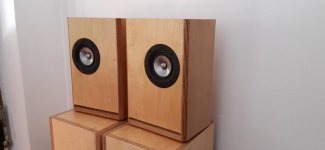
For those interested, the 'unorthodox' system I described in
An Unorthodox and Affordable 1st Class System
may undergo a physical change. Why? Mostly because it's a hobby and it's never finished. But I thought my latest unit under test might be of interest if only because of its seeming absurdity.

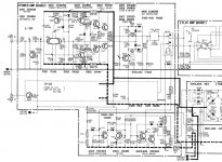
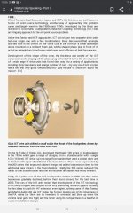
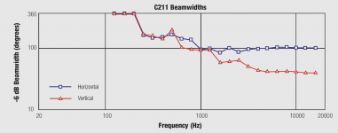
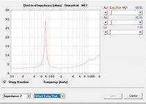
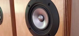
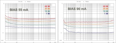
The system already employs the (IMO magnificent) Atlas CJ-46 horn and PD-5VH driver for midrange duties, currently set at 200hz-3khz. But as you've probably noticed, there's a persistent and near-universal urge to extend horn response as low as possible. A little fishing around made me too curious to avoid looking at another horn/driver setup, currently as mentioned under test. I expected to pack away both items and send them back after observing either poor performance (for my hifi uses) or simply not enough improvement to justify trying to implement a pair. The horn is an Atlas DR-72, the driver an Atlas PD60A. Though seemingly equipped with transformers (I haven't looked yet), the driver is configured for straight-thru 16 ohm connection. Typically drivers of this sort have been taken apart and the transformers totally disconnected. Here I'm not sure. Tests have shown undistorted output down to 150hz, slight distortion at 140 and very visible (though oddly listenable) at 130. Considering where I drive the extant horns, I extrapolate that I could take down the high-pass to perhaps 175hz (or lower?).

Worth it? I'm not sure yet. Amplitude variations, which are smooth, can be compensated. Phase response was pretty stunning, better even than the extant horns/drivers. HF extension is fine (3khz will be the low-pass). Efficiency is absurd. So what's to stop my buying another horn/driver and trying this out? The cost increment over the current setup is only ~$220.

At this point, the concerns are
* not enough testing yet.
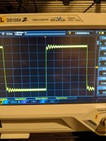
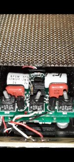
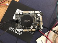
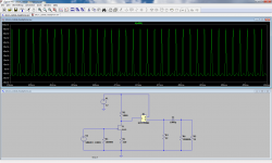
* possible ringing from the all-aluminum structure (CJ-46 is fiberglass), though I haven't sensed any. The scope showed remarkable reproduction of repeating 300hz and 3000hz tone bursts. But even if ringing showed up, the horn bell exterior could be damped easily enough.
* efficiency is so great that idle noise actually may be an issue. I think I can compensate, with shunt resistors if nothing else.
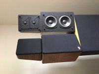
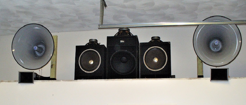
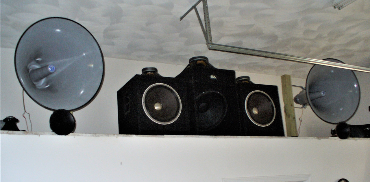
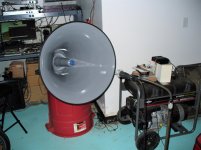
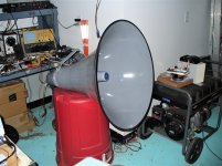
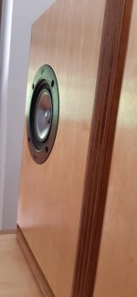
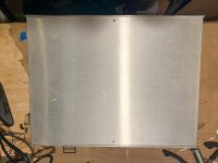
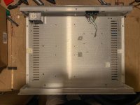
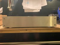
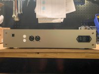
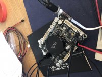
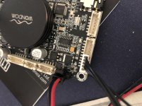
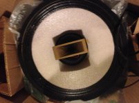
* the real reason --- the sheer size. Note photos. Yes, that is an inverted industrial trash can on which the UUT is perched, and that is a good-size mobile home generator next to it. Mouth diameter is spec'd at 31" (it's really 30" according to my yardstick). Oddly though it's not that heavy.

But so far, at least, things are trending toward a 'yes'.

dr72_1.jpg
dr72_2.jpg


UPDATE 9/12/20: Despite bad placement, dropped the buzz/scope tests to hook it up to the actual system and hear real music. Results even more surprising than scope tests. Where's my wallet?


UPDATE 9/19/20: And here it is. The sound is magnificent and midrange has never been so well defined. Void of 'harshness'. I think I'm starting to like round horns. The sound is smooth and melodic, not at all what you might think from the picture. Crossover to mids at 180hz. My 15" Altecs appear to have shrunk!


bighorns.jpg


UPDATE 9/23/20


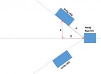
For no real reason I decided to find out whether a round-mouth tweeter might make a better match for the big mids. I already had two Eminence F110M drivers (their smaller ring radiator) and a couple of Dayton H08RW horns sitting around so I tried the combo. I don't know if it's 'better', but it certainly doesn't sound worse. Tests well too.


allrounds.jpg

Attachments

  • dr72_1.jpg
    dr72_1.jpg
    471.8 KB · Views: 156
  • dr72_2.jpg
    dr72_2.jpg
    570.2 KB · Views: 139

3e or Wondon DSP for Active Speaker

I need to develop a two way crossover for an active speaker. The active speaker will be for Bass Guitar and/or PA Top.I should add that my colleague has been designing analogue crossovers for years and has all the equipment neede to measure the speaker's performance and fine tune it


The rough spec is:


  • Active crossover between the woofer and tweeter. So one input and two outputs are all I need although I could build in a subwoofer output if there is enough processing power.
  • It should have phase adjustmet to time align the drivers.
  • HPF at up to 24dB/octave. Frequency would be between 30-40Hz
  • Parametric and.or Graphic EQ to smooth the response.
The 3e boards seem to find favour here but the Wondom system is complete, including all hardware needed to programme and operate the DSP system.


What are the advantages of each for my application? Are there latency figuires for the Analog Devices Chips?

Formula? Lining interior of sealed/ported cabinet.

I am making a cabinet for a Celestion F12-X200 speaker (this is an FrFr speaker).
I started following their suggested cabinet design (sealed, ported) but found
the dimensions to be not quite right for me.

So, being a programmer I writing a program that allows me to design a cabinet
for the F12-X200 (imperial / metric measurements, Yea from us state-side wood workers for Imperial!)
that allows me to design different sized cabinets, different configurations (Dual F12-X200's, Slant cabinets).

I am about 80% through the mathematics (TS, Tuning, Port Length,...) but in the back of my mind is the
fact that the Celestion Design for the F12-X200 calls for lining the inside of the cabinet with 'Polyfill'.
There is no property data given on the weight / density / thickness of the polyfill itself.

I somewhat understand what lining the interior of the cabinet with poly fill will do but it seems that the effect of it can only be arrived at via empirical data. meaning their is no real science or formulas behind it.
I constantly see sentences (on this four and others) such as:
- 'Most estimates say between 15-25% theoretical volume gain'.
- The use of 'estimates' and 'theoretical' in the same sentence somewhat bothers me.


I took a brief glance at WinISD (which seems to be a really old share-ware type application) and though I do
not have all of the required parameters from Celestion I see that they are applying some sort of formula:
- They use 'Qa' as 'absorption losses'.
It is my understanding that the value of Qa is reflected thusfully::
- 100. Bare Box
- 50. Lined Box
- 10. Stuffed but not over compressed.
- 5. Stuffed and compressed.

And that the lowering of Qa is seen at:
- SPL
- Impedence Charts
- Qtc

They of course are using a formula.

So, is anyone aware of any sort of formula that can be used to model the effects of lining the interior of a ported sealed speaker cabinet?

Thanks

Dual Drivers in a line array cabinet

Guys,

Need a little help here, I have 40 manufactured line array cabinets with 2x8" lo drivers and a 1" HF. The 8" lo drivers are in series and mounted next to each other spaced 8.35" apart. Crossover from 8's to 1" is approx 2.5k. I know I have destructive interference issues on the lo side with the 8's but I would really like to pinpoint the frequency. I am toying with changing these to 3 way but there are other issues with driver isolation issues as the 8's share a chamber. I am open to suggestions here as they sound ok but would really like to take these to the next level if economically possible.

Thoughts, besides dumping these and getting something else?

Understanding transients according to roll off or just in general

Which roll off would have better transients the vented or sealed? I mean, how do we tell how a roll off effects transients?

Essentially, I am looking at making a sealed cab and crossing over anywhere above 100hz as my subs play clean up to 180hz without boominess. I am just curious if its worth putting port in it to plug and have as a secondary option as they are about the same size. The vented is larger but I will be making a larger sealed cab anyway, to hit a lower QTC.

I am looking for maximum transients and punch. The driver is the Deltalite 2 2515.


2515 Vented Roll off.jpg

2515 Sealed Roll off.jpg

2 way synergy top

I wanted to try out building a synergy horn, perfect timing now that we want to replace mid-tops on our ghetto party stack.

I'm thinking of going for 2 Fane sovereign pro 10'' and p audio BM-D750 cd. Plan is to place it directly on the subs and cross it at 120, and push the fanes to 1000hz.

I tried simming it out in hornresp, but feel like the back chamber got awfully small. Will it work or should I increase the chamber a bit?
Would also love some general feedback on the design (or driver choice). The sims are xover at 120-100-1000.

Attachments

  • disp-chamber.JPG
    disp-chamber.JPG
    48.8 KB · Views: 213
  • horn-totalpower.JPG
    horn-totalpower.JPG
    44.7 KB · Views: 207
  • imp-port.JPG
    imp-port.JPG
    40.8 KB · Views: 208

Cathode degeneration in Output Stage?

I often see input stages and occasionally driver stages where no cathode bypass capacitor is used, either to control gain, or give a more favourable distortion spectrum.

Rarely, if ever, have I seen a single ended output stage with an unbypassed cathode resistor.

Why is this?

Is it simply a waste of output?

Is it the increase output impedance?


Recently, I completely re-jigged an amplifier I have been working on, and the configuration I ended up with, was no cathode bypasses, throughout all 3 stages of the amplifier, including the Output stage.

The performance was quite good, and stability/frequency response, was better than my last attempt at harnessing Global feedback - an attempt, which I thought was very promising, until I took a frequency sweep and saw a rising output, all the way to 75kHz!

Embarked amplifier + DSP + BT + WIFI for prototyping and more

Hello,


I'm very grateful of the support I received on this forum.
I've been able to release my first working prototype of an active parabolic speaker for home (check https://www.diyaudio.com/forums/planars-and-exotics/352353-project-parabolic-speaker-7.html ).


Now that I have secured the help of a designer to make it nicer in the living room, I try to secure the next steps: a second prototype and getting ready for a small serie (1000 units).


For the second prototype, I want to find the simplest way to embark in my speaker:
- amplification
- DSP (that I will configure at build time, not for customer)
- BT 5/WIFI (DLNA, Airplay) as source
- USB (charging and source)


I turn toward PC-based as I feel it will allow me to control better the software auto-updates.

What would you recommend me to explore?


cheers,


JLo

FS - Alpair 7.3 Silver-Grey in Planet 10 CGR Baltic-Birch Enclosures

Here is a pair of Alpair 7.3 Speakers in Silver-Gray. These are in the Classic Golden Ratio boxes designed by Dave dlugos of Planet 10 Audio. These are 15mm Baltic Birch lined with Natural Wool dampening.

Neutrik Speakon connectors are used on the back. These sound fantastic on a desktop nearfield or in smaller rooms. I preferred them high passed at 60 hz. with a sub.

These are located in Vienna, Austria. 200 euros plus shipping. Paypal friends and family.

Feel free to ask any question. Thanks!

Attachments

  • alpair1.jpg
    alpair1.jpg
    33.9 KB · Views: 224
  • alpair2.jpg
    alpair2.jpg
    46.9 KB · Views: 215
  • alpair3.jpg
    alpair3.jpg
    43.4 KB · Views: 218
  • alpair4.jpg
    alpair4.jpg
    51.6 KB · Views: 217

P-P with EL34/KT120

Hi

I have published a project on Audioreview magazine in Italy about a push pull amp that use EL34 or KT120 with fixed bias, pentode configuration.
It uses a 6922 for input, ECC99 for splitter.

In fig. 1 there is the inut diagram
In fig. 2 the splitter
In fig. 3 the output

The voltage is around 430 vdc, the bias current is zout 30mA.
I used a one trafo for HT supply with 4 caps of 470uF -450 Vdc.
One toroidal trafo only for filaments and neg bias.
The Output trafo is made by F.I.A.T. of Roma with a C core; ratio is 27:1 the secondary is one at 5 ohm.
The global feedback is about 18 dB

In fig. 6 there is a very intersting test we normally use in the Lab of Audio, it is a particular test to check the power of an amp with continuous or impulsive signal
The AP1 is driven by a software written for this purpose, we have a resistive load with. 6-8- 5,3-4 -3,2- 2,7- 2,2- 2 ohm the there is an interface driven by AP1 that change in sequence the load, the software detect in automatic the distortion (written on a window where is possible to put the information of the amp as max power and the max level of THD we want to test).
When the THD defined previously is reached the software change the load and so on.
This test is continos and impulsive; in theory a perfect amp have a vertical line; more the line became orizontal less the amp can delivery currento on load.
In fig. 6 there is a result with EL34 at 35 mA of bias; the power on 8 ohms is 41.5 Watts , at 4 ohm are 26.4 (it is reasonable); if we look on red line (contineous input signals) we see that the line become horizontally for a lower value of load.
The blue line is impulsive and it is better, of course.
In fig. 7 there is the freq. response for three different power; it is very wide.
In fig. 8 there is a THD vs freq. test for four differetn power level; the results is good because the line is costant for frequency with an increment at low freq.

The we put the KT120 on this circuit and something is happened.
In fig. 9 the test with a bias current at 90 mA (in this situation we have class A until 32 Watts), we can see that the power is much better due to the internal lower resistence of the tube compare with the EL34.
We reach 57 Watts impulsive on 8 ohm and 76,9 watt on 4 ohms.

In fig. 8_90 there is a freq. response that is similar with EL34.

In fig. 6_Bias there are two results for a bias at 55 mA and 90 mA , we can see the difference. Also in this case a good results mainly for the higher current, of course.

The use of a KT120 or KT150, where is possible, give us a better performance because the capacity to drive more current due to a lower Rp ; mainly when the trafo, at low and high frequency, has the tendence to get a lower L.
A good performance are obtained with 6CA7 EH, very very good. It has a 30% less in the Rp of EL34B Tungsol I used.


Ciao

Walter

Attachments

  • Figura 1_6922_srpp_input.gif
    Figura 1_6922_srpp_input.gif
    39.9 KB · Views: 2,413
  • Figura 2_ECC99_phase_splitter.gif
    Figura 2_ECC99_phase_splitter.gif
    42.2 KB · Views: 2,425
  • Figura 3_stadio_uscita.gif
    Figura 3_stadio_uscita.gif
    52.1 KB · Views: 2,455
  • Figura 6 - CCL.gif
    Figura 6 - CCL.gif
    344.9 KB · Views: 2,305
  • Figura 7 - RISP.gif
    Figura 7 - RISP.gif
    269 KB · Views: 2,027
  • Figura 8 - THFR.gif
    Figura 8 - THFR.gif
    206.9 KB · Views: 717
  • Fig.9_90MA_CCL.gif
    Fig.9_90MA_CCL.gif
    302 KB · Views: 666
  • Fig.8_90MARILI.gif
    Fig.8_90MARILI.gif
    265.7 KB · Views: 620
  • Fig.6_BIASTHFR.jpg
    Fig.6_BIASTHFR.jpg
    478.4 KB · Views: 782

Plinius CD-LAD schematics

Hello,

Could someone share Plinius CD-LAD preamp schematics? I have a problem with remote volume control - the potentiometer's motor works fine when connected to a DC source, the amp board gives 4,2 V to the motor when measured with the motor disconnected, but when I connect the motor to the board and press either vol up or down on the remote, the amp switches itself off for a second and then restarts.

Determine HP-freq for compression-driver?

Hi.

Let assume I'm pretty cheap and bought some compression-drivers with zero data-sheet. Yes, that's a gamble, but they were very cheap. I've tested one with a 24db HP @2200Hz and it sound OK for a party-speaker. 1,5" diaphragm, and magnet around Ø100mm. Appears pretty solid.

So now, I'm considering a new design where I would want to cross lower. Maybe around 1300-1500Hz. How would you determine the lowest cross-over for a unknown compression-driver?
Based on resonance-freq, distortion chart (at high power?), others?

Design-goal: one comp-driver in a Mrh-80 horn from Monacor (115mm deep), paired with 2*6.5" midbass with a sens. of 91dB. Electronic cross-over and power for midbass around 300W peak.

Kind regards TroelsM

1W - 7 Components American Beauty Buffer

Very simple to build and with outstanding quality parameters. It only requires an adjustment. The output current is properly compensated so as not to expose the output stage to risk.

It should be used with high-performance speakers or it can be used for headphones.

Its outstanding points are: very low distortion and very stable throughout the audible bandwidth, high PSRR

attachment.php


attachment.php


attachment.php


attachment.php

Attachments

  • 1WABB Schematic.jpg
    1WABB Schematic.jpg
    70.8 KB · Views: 1,991
  • 1WABB Fourier Analysis.jpg
    1WABB Fourier Analysis.jpg
    465.6 KB · Views: 1,871
  • 1WABB PSRR.jpg
    1WABB PSRR.jpg
    245.3 KB · Views: 1,899
  • 1WABB AC Analysis.jpg
    1WABB AC Analysis.jpg
    573.7 KB · Views: 1,867
  • Thank You
Reactions: ginetto61

0.5 woofer on a 2.5way

Satori mw16 are praised for their midrange, but here and there I've read some bad opinions on their bass performance being lumby, slow, soft, subwooferish etc.

For money saving and since there are probably some better drivers on the bass department, could I use another driver for the 0.5 woofer?
If yes, should it be at its own volume? I guess it should be same impendance and sensitivity?

Hello from Pangolin!

Hi everyone!

My name is William Benner. DIY Audio Forum is certainly full of great information and a lot of expertise, and that's why I'm here.

My company Pangolin manufactures laser systems that are very often used in concerts and special effects. The lasers are projected using very small motors that we call "Scanners". The impedance and power handling capability are very similar to speakers, so we often wind up using audio power amplifiers to drive them.

It's great to become a part of this community!

Best regards,

William Benner

UltraBib vs. LinearPi+UcConditioner

Hey,

have a RPI3A+ with DIY AD1815 NOS Hat-DAC which has now a simple cheap PSU, which feeds the RPI. DAC is powered by RPI through GPIO.

Want to update the system with a linear PSU. Can give power input directly to DAC and feed the RPI as well through GPIO from DAC. So I need just one linear power input.

I am thinking about using a UltraBib1.3 by Salas vs new LinearPI+UcConditioner by Ian Canada.

1st would be cheaper, but more to assemble. I am a noob, but think will find help from friends and learn to solder.

2nd would be more expensive, but easier to assemble. just 2 supercaps to solder.

does anybody have recommendations or experience in sound improvement? what would be better? thanx in advance.

Orange TH30 amp: weird components ?

Hi,
Since there were no schematics available, I've traced most of my Orange TH30 amp (preamp, loop driver, PI, power stage).
For reminder, it's a 2-channel preamp with a quad-EL84 power stage.

I can post my crappy drawings here if anyone's interested, however this amp looks like an EL84-driven Rockerverb 50 MK1 (its schematics can be found online):
- Clean channel: almost identical to RV50
- Dirty Channel: identical to RV50 (except one cathode bias resistor)
- Dirty Shape Control: identical to Dark Terror
- Loop Driver: identical to OR15
- Phase Inverter: identical to OR15

However, I noticed 2 weird things:
- The bass pot (in the Clean Channel tone stack) is a linear 250k pot, whereas it's a logarithmic pot in all the Orange tone stacks I've seen yet
>>> could that be an error made at the plant ? I already noticed that the bass control was not very "responsive"...

- For each EL84 valve, there's a 2k2 input resistor coming from the Phase Inverter into the valve grid (pin 2)... except for one valve, where this input resistor is only 1k !
>>> here, I'm kind of lost, why change this on only one of the 4 valves ? Crappy biasing for bad factory valves ?

Any advice would be very appreciated, thanks 🙂

Par-metal 16x12x3" chassis with FPE panels

This is a Par-metal 16x12x3" chassis that I used for a Twisted Pear Audio Buffalo 3 DAC.

It will be sold with 2 blank panels, and 2 rear milled panels from FPE for IEC, XLR and RCA jacks. One panel has a square opening for USB, the other has an additional "XLR-style" socket.

Chassis itself costs about $100, panels >$100, filtered IEC ($20).

I am asking $80 + $10 flat-rate shipping in US.
The bottom plate is fairly drilled but you could still buy only that part from Par-metal and save alot if the panels are right for your project.

Attachments

  • 2020-09-07 19.35.27.jpg
    2020-09-07 19.35.27.jpg
    202.8 KB · Views: 246
  • 2020-09-07 19.41.50.jpg
    2020-09-07 19.41.50.jpg
    198 KB · Views: 244
  • 2020-09-07 19.41.55.jpg
    2020-09-07 19.41.55.jpg
    140.7 KB · Views: 237
  • 2020-09-07 19.42.05.jpg
    2020-09-07 19.42.05.jpg
    150 KB · Views: 237
  • 2020-09-05 23.42.57.jpg
    2020-09-05 23.42.57.jpg
    162.8 KB · Views: 236

OPAMP rail-to-rail opamp <3.5V for audio ??

Good morning,

My name is Cristian, I have been reading the Forum for 2 months (approximately). I'm interested in the world of audio, in fact, reading the forum and its recommendations, I already built the first circuit with an OPAMP NE5532.

Now, I have a problem, I need a maximum output of 3.5V (peak to peak, 3Vp-p would be acceptable too), since the ADC input of the microcontroller I am using works with that maximum voltage. I already managed to do it with a simple voltage divider on the output (as the attached image shows). However, I would like an alternative, an OPAMP that can be fed with + -1.75 or + 3.5V at 0V, to be able to feed my complete circuit using only a 3.6V battery. Is there an OPAMP with those characteristics?

The input is an electret microphone.

I know that the LM5532 can be powered with + -1.75V, but the recommended minimum is + -5V.

I hope you can help me, I would be very grateful.

Attachments

  • OPAMP.PNG
    OPAMP.PNG
    64.2 KB · Views: 230

Why tie input ground to earth ground?

I've got a tubelab sse that I built a few years ago. I'm very happy with it. With the inputs disconnected, there is almost no noise/hum at all. I'm trying to troubleshoot why I'm getting some once I connect the inputs.

My main question, though, is why do we tie the input ground to the power/earth ground?

It seems like we should certainly tie chassis (and all metal external surfaces) to earth ground for safety. So I'm onboard there.

What purpose does tying the input ground to earth ground serve though? The circuit would still have a "common" tied to the input "ground". It seems like pulling the input ground down to earth ground would cause ground loops though. Let the circuit ground exist at the same potential as the source (by "grounding through" the input connector) and let the earth ground exist purely for safety.

What am I missing?

Tight Soldering Spot, Help Needed

Good day & hope all are well~ If you check out my picture, you'll see those 3 dip switches, & the 2 end switches need to be replaced, but my technician can't get in between those 2 green wafers to unsolder the bottoms of the switches, and the wafers don't easily separate. Who locally could I turn to to help tackle this tricky job,,, a jeweler, a blacksmith ��,,, any thoughts?
Thanks so much in advance for your help~
Stay well~
Kenny

Attachments

  • Screenshot_20200910-125204_Gallery.jpg
    Screenshot_20200910-125204_Gallery.jpg
    373.9 KB · Views: 156

Jab3 with DSP - quite stuck - noob asking for help

Hi everyone

Have bought the Jab3 with DSP and 2x50 w.
Hooked it up today to test it, with my drivers and for some reason i only got the slightest of sound from the woofer and tweeter. Almost just a whisper.

Hope you can see my attached images.

I'm clearly doing something wrong!

Used line in and hooked up my iPhone on spotify.

For the woofer i used 1 and 2 ( 4 pin with 4 wires called 1,2,3,4) and for the weeter 3 and 4.

Did not however think it would matter if wire 1 went to a specific input on the speaker ? I am a noob 🙂

In the DSP i made a simple crosser over - so not really anything I have made wrong there .. yet.

I just don't understand why it would play at a whisper and not just as a speaker would normally. Does anyone have ANY hint for me ?

Attachments

  • IMG-5406.jpg
    IMG-5406.jpg
    878.2 KB · Views: 88
  • IMG-5405.jpg
    IMG-5405.jpg
    990.5 KB · Views: 101
  • IMG-5404.jpg
    IMG-5404.jpg
    1,005.3 KB · Views: 90

2.1 buy or build for a friend?

Hi all,
After the highly successful build of my Woden Bloodhounds (thanks so much for all the help!!), my buddy saw them and wants me to build him something for his living room/TV space.
He just wants something better than his current TV sound, with maybe going to surround in the future. I'm thinking a decent 2.1 setup with a small dedicated amp at the moment might be his best option for price and flexibility.
His space is fairly large and open (maybe 18'x22'), with very high ceilings (~12'), hardwood floors, exposed masonry/plaster walls. It's a renovated upstairs store space. Very cool pad, actually. 😉
Anyway, as much as I'd love to build him something from scratch, I don't want to do him a disservice by not suggesting he buy a pre-built set, if that would be the best solution for now.

If building, I was thinking about maybe something floor-standing, but slim. I've seen a beautiful design with a curved back panel, can't recall the name now.
I was leaning towards just buying a sub for now, since I'm not up for a sub build I don't think. I was thinking about the BIC Acoustech H-100II, unless you folks know of a better option for the money?
So what do we think, buy or build?
I'll try to answer any questions I can. Thanks in advance for all the great info I know I'm about to get. You guys are awesome! 😀

Help me understand SiC mosfets

Newbie here. I've simulated the J-Mo 3 headphone amp and was wondering if any of the big silicon carbide mosfets could be used in place of the IRF510
https://www.diyaudio.com/forums/headphone-systems/310544-jfet-mosfet-headphone-amplifier-mo-3-a.html


Doing some reading it looks like they need a higher gate voltage, that I get. But in the simulation it looks like the gate is really dragging down the voltage from the J113. Like it's too much of a load?


Can these mosfets be used at low voltages or are the characteristics just not right for this application?

Attachments

  • sic_mosfet.png
    sic_mosfet.png
    104.5 KB · Views: 293

Single Goodmans Triaxiom 250c

Single Goodmans Triaxiom 250c 12" dual-concerntic speaker,
16 Ohm. Crossover: coil + one capacitor + Lpad.
Shipping weight ~22 lb, UPS cost: US west coast ~$30, east coast ~$60.
Non fatigue ... 60's sound...
This is my spare: bought from ebay, was a dud ... HF is replaced.
Tube amp friendly: ok with SE 2A3.

Caveat:
1. HF is replaced
2. don't drive it with solid state, it will blow the HF in no time.
3. likes big enclosure: aperiodic loading ... needs
7,800 cubic inches, see Goodmans ARU
https://worldradiohistory.com/Archive-All-Audio/Archive-Audiocraft/Audiocraft-1957-08.pdf

Free to a good home.
First come first serve, US preferred due to shipping cost.
Please PM mailing address. Thanks.

Attachments

  • GoodMans_triaxiom.jpg
    GoodMans_triaxiom.jpg
    664.6 KB · Views: 110

ESL57 audio transformer wiring

Hi everyone , new poster here, I'm currently refurbishing some ESL 57's but I'm having difficulty identifying the post numbering on an early audio transformer(all the panel wires have been removed) The later type have the posts sequentially numbered 1-15 +earth post. With my early type there are 12 posts+ the earth and another 3 on a seperate board.I beleive these are not numered sequentially and I do not want to rewire incorrectly. I would be most grateful for any help.
Dave

LED voltage rating in an illuminated pushbutton switch

I'm wondering if someone could help me understand this datasheet better.

I'm looking at this particular E-switch illuminated push button switch
https://sten-eswitch-13110800-produ...em/asset/product_line/data_sheet/251/SAV7.pdf

What I'm trying to figure out is that LED voltage rating that they list. The only ones I can find in stock are the 3V LED variants.

In the LED schematic from the datasheet though, they show the LED portion as just a pair of LED's in opposite orientations, but no limiting resistors.. Is there some reason I couldn't just use 12V or something like that, with an appropriate limiting resistor?

Where would the 3V rating come from?

Reconing kit for unbranded speakers

Hi there, I am trying to get into the wonderful world of speaker reconing/recoiling. To start of I have acquired some unbranded 12" drivers that someone was throwing out. The frame looks to be in good shape the cone has disintegrated.
What specs should I use when buying a reconing kit?
There are two tweeters as well with the coils opened, again unbranded. What should I keep in mind when ordering replacement?
Any further tips/advice on the matter would be greatly appreciated eg. what tools I should get, glue etc.

Thanks in advance.

Powerbeats 2 headphones

I am in constant contact with many American group action websites and I have just been notified that any purchaser ( in the USA ) who purchased them before -August-7-2020 may be eligible to claim $189 --or more from a class action settlement .


While no proof is necessary to submit a claim if you have a receipt it could mean more money in your pocket.
Claim deadline-Nov. 20 -2020.


Fault--- they stop working or charging after minimal use .


Sorry UK --- American customer protection laws are far superior to UK laws on this subject and I should know after years of trying to help UK citizens .


Apple agrees to pay $9.75M settlement over alleged Powerbeats 2 ‘design defect’ - The Verge
Projects by fanatics, for fanatics
Get answers and advice for everyone wanting to learn the art of audio.
Join the Community
507,837
Members
7,890,262
Messages

Filter

Forum Statistics

Threads
406,349
Messages
7,890,262
Members
507,837
Latest member
PaulPagoda