Alpha Nirvana 39W SE Class A Amplifier GB
- By xrk971
- Group Buys
- 155 Replies
This is the Group Buy and Build thread for the Alpha Nirvana 39W SE Class A amplifier designed by AKSA. The technical discussion thread is here:
Alpha Nirvana 39w 8ohm Class A Amp
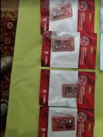
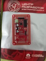
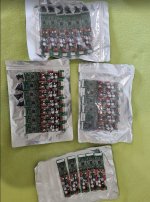
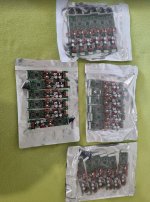
PCBs:
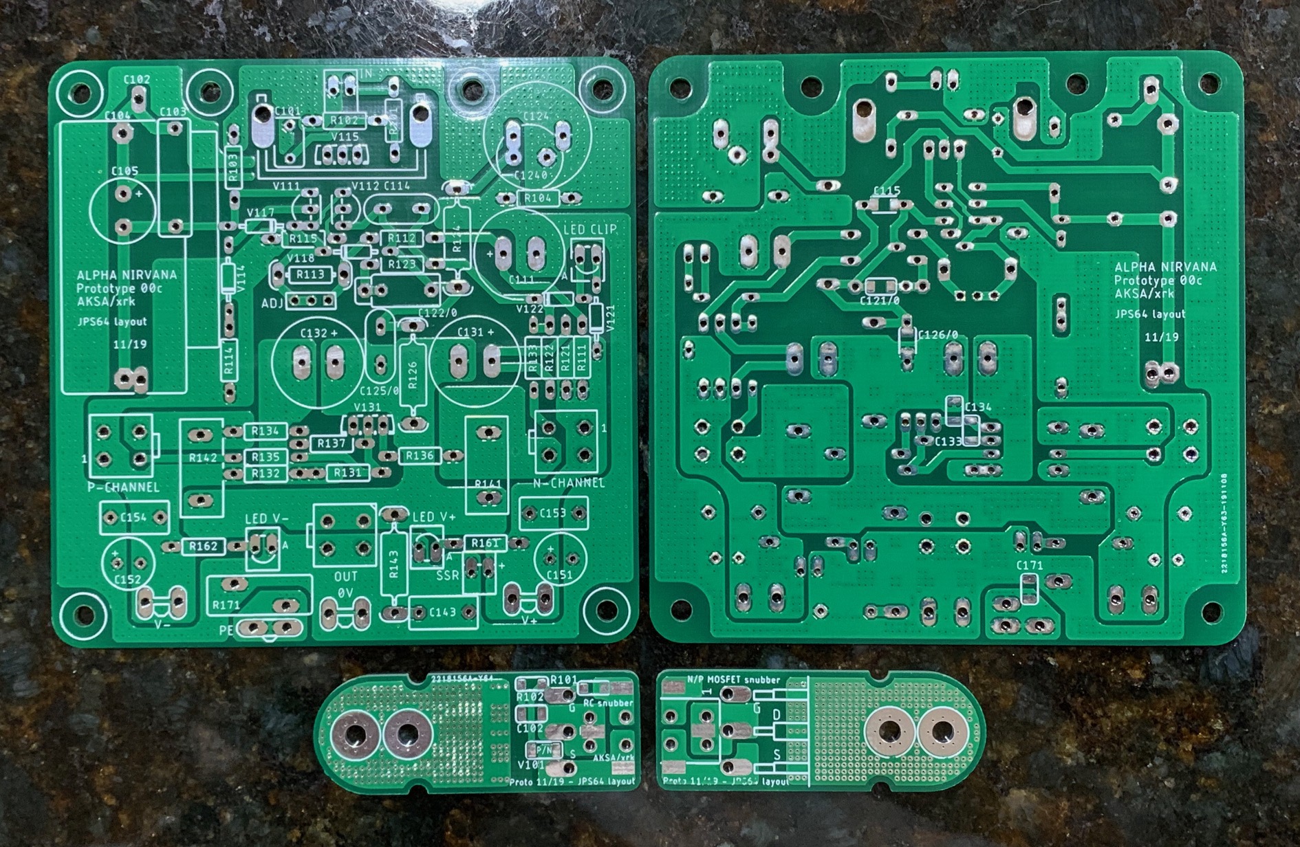
Production ones will be 2mm thick, 2oz Cu, ENIG gold finish, and Blue solder mask.
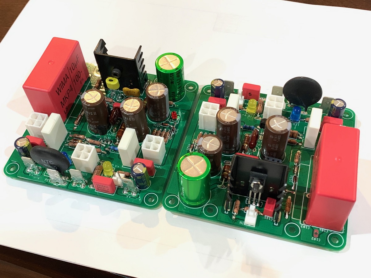
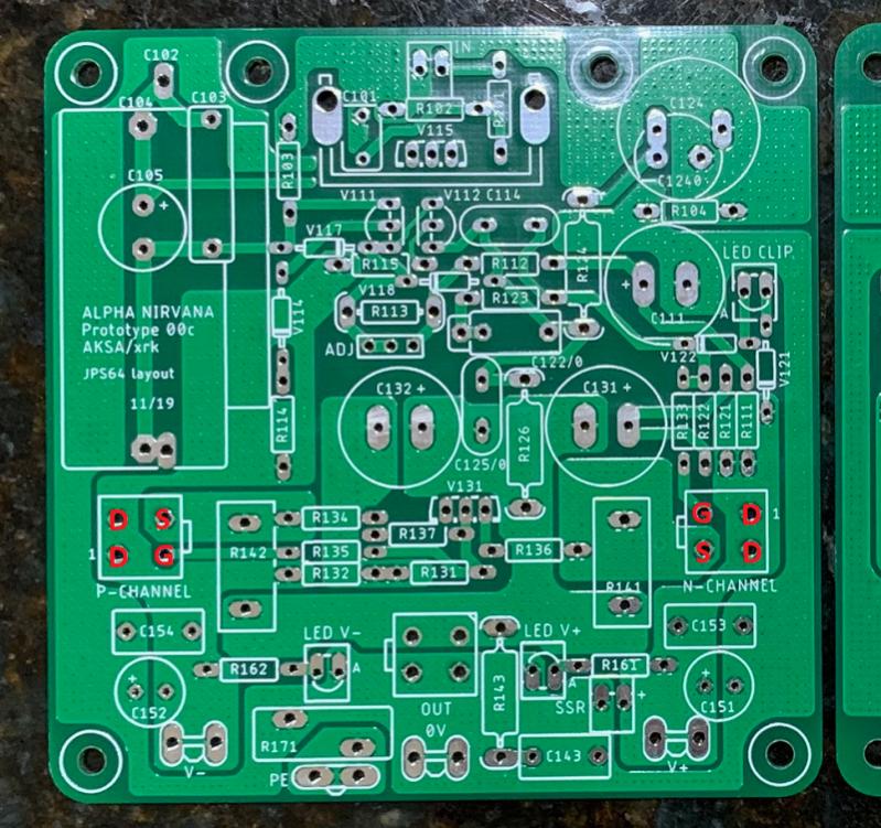
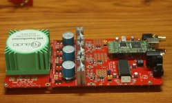
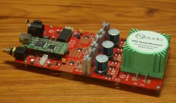
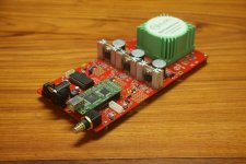
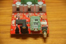
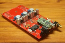
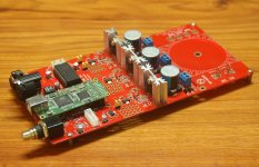
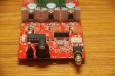
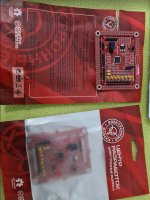
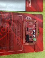
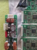
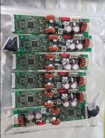
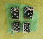
Amp module looks like this assembled:
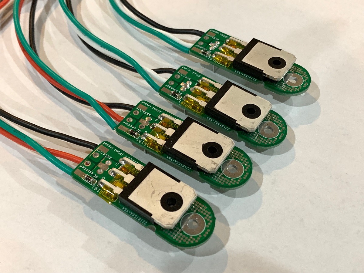
Includes helper snubber boards to allow remote mounting of MOSFETs for flexibility and ease of installation by decoupling the installation of the PCB and the MOSFETs:
Latest Schematics and BOM will be updated soon, but current version (very close to final) is below:
I recommend use of these Fairchild MOSFETs (higher power rating than IRFP's):
FQA40N25 ON Semiconductor / Fairchild | Mouser
FQA36P15 ON Semiconductor / Fairchild | Mouser
The SLB PSU is also highly recommended - proven to work with single SLB and Antek 600VA 24v (AN-6224) trafo. Should work as dual monoblock with dual SLB and Antek 300VA 24v trafos (or equivalent). Also, a ready to run (RTR) solid state relay (SSR) DC protection is highly recommended to prevent turn on thump and provide safety net for your speakers should something fail.
Also tested to work on DIYA Store Dissipante 4Ux300mm chassis. Board is UMS compliant and I did not have to drill and tap a single hole on my UMS heatsink. Chassis temp is 57C at hottest point in 20C ambient. A 5Ux400mm would be much more generous and allow higher bias current.
Pre-Orders are now being taken in my Etsy shop for the GB.
Pricing is $37ea (includes pair of snubber boards - which cost almost as much as the PCB, hence the higher price). Thus, a stereo pair requires two boards. Free shipping in USA. Etsy calculated shipping elsewhere - circa $23 via tracked and insured USPS First Class mail.
If you place a pre-order, please add your name to a running list below with name, qnty, country. Thanks!
A huge thank you to Hugh (AKSA) for the design and JPS64 for the superb professional layout.
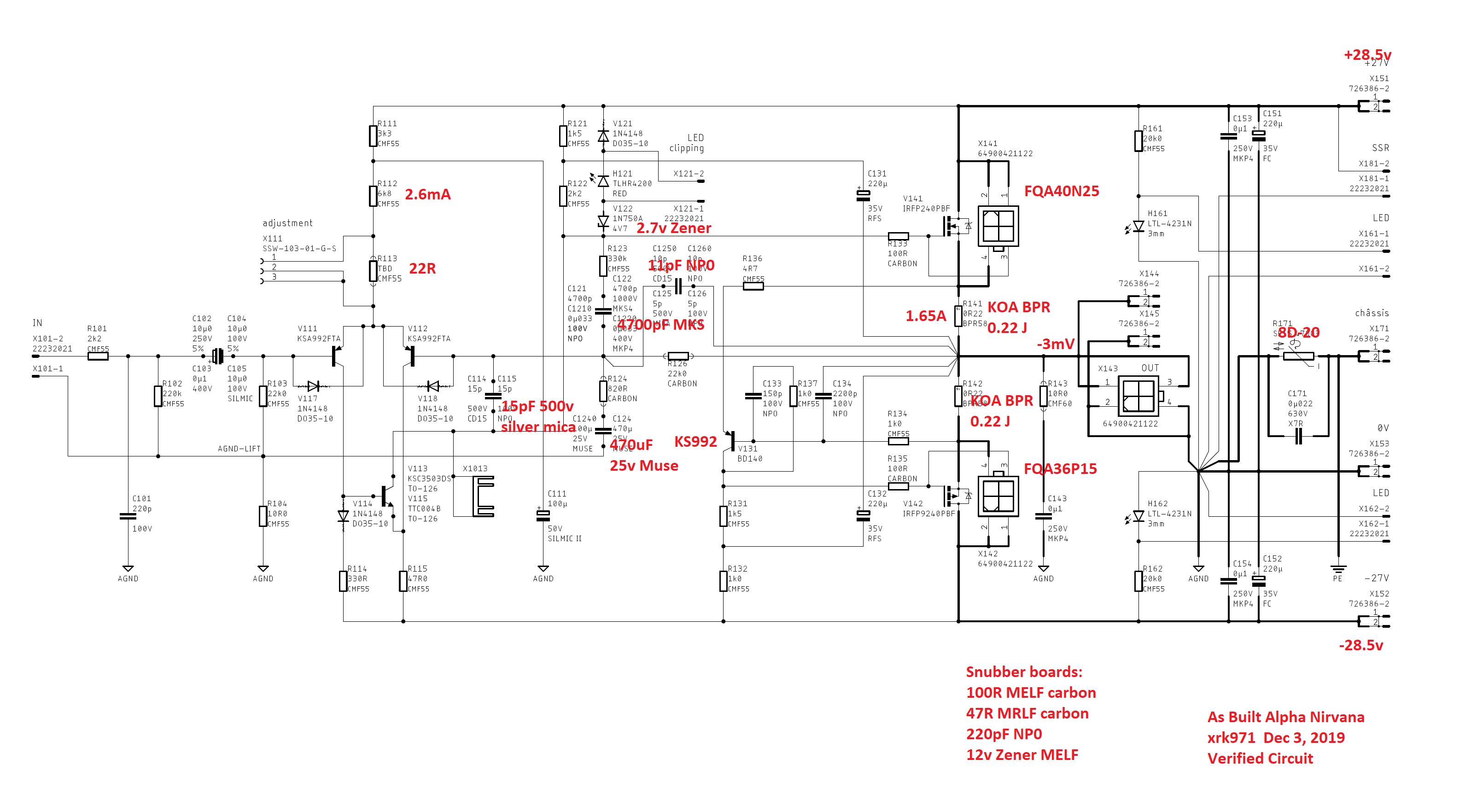
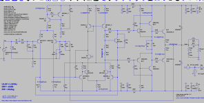
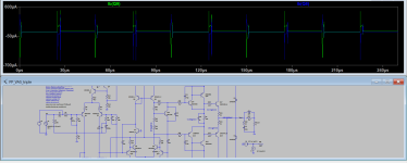
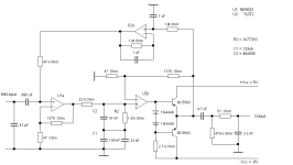
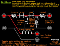
Here is the schematic of my amp "AS-BUILT". These values should work and clears up any ambiguous locations where multiple values are possible.
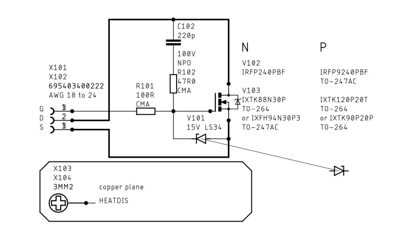
Schematic of snubber boards:
Edit Dec 26, 2019: AndyR has put together a nicely annotated BOM for both the 8ohm and 4ohm versions here:
Alpha Nirvana 39w 8ohm Class A Amp
Edit June 13, 2020: note that the feedback resistor R126 and R124 could 1% metal thin film or hand-matched carbon film as 1% not available at reasonable price. This needs to be done to get the same gain from left and right channel. It’s more important that they are matched left and right and not for absolute value. Also note that metal oxide thick film should not be used (dominant H3 and high THD). Do not use carbon composition - that is an error in the BOM. Sorry about that. Carbon film will have a slightly higher THD but more H2 vs H3. Metal thin film will have lower THD but relative H3 will be closer to H2 but H2 still dominant. Safest bet is use 0.5% metal thin film for these 2 resistors. But I personally like the carbon vs metal thin film.
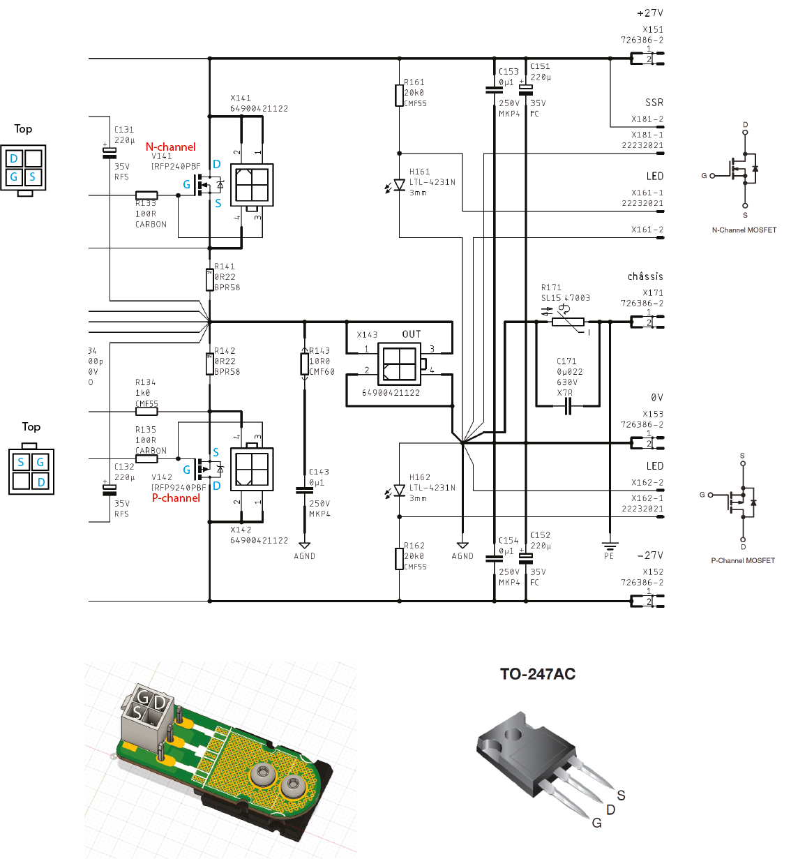
Edit Feb 7, 2020: Pin diagram for Molex quick connects to MOSFETs
Edit Mar 11. 2020: helpful pin diagram for MOSFETs
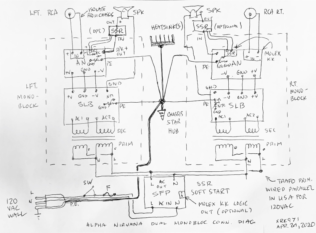
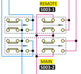
Edit Apr 24, 2020 - Dual Monoblock Connection Diagram if using SLB PSU's:
Alpha Nirvana 39w 8ohm Class A Amp
PCBs:
Production ones will be 2mm thick, 2oz Cu, ENIG gold finish, and Blue solder mask.
Amp module looks like this assembled:
Includes helper snubber boards to allow remote mounting of MOSFETs for flexibility and ease of installation by decoupling the installation of the PCB and the MOSFETs:
Latest Schematics and BOM will be updated soon, but current version (very close to final) is below:
I recommend use of these Fairchild MOSFETs (higher power rating than IRFP's):
FQA40N25 ON Semiconductor / Fairchild | Mouser
FQA36P15 ON Semiconductor / Fairchild | Mouser
The SLB PSU is also highly recommended - proven to work with single SLB and Antek 600VA 24v (AN-6224) trafo. Should work as dual monoblock with dual SLB and Antek 300VA 24v trafos (or equivalent). Also, a ready to run (RTR) solid state relay (SSR) DC protection is highly recommended to prevent turn on thump and provide safety net for your speakers should something fail.
Also tested to work on DIYA Store Dissipante 4Ux300mm chassis. Board is UMS compliant and I did not have to drill and tap a single hole on my UMS heatsink. Chassis temp is 57C at hottest point in 20C ambient. A 5Ux400mm would be much more generous and allow higher bias current.
Pre-Orders are now being taken in my Etsy shop for the GB.
Pricing is $37ea (includes pair of snubber boards - which cost almost as much as the PCB, hence the higher price). Thus, a stereo pair requires two boards. Free shipping in USA. Etsy calculated shipping elsewhere - circa $23 via tracked and insured USPS First Class mail.
If you place a pre-order, please add your name to a running list below with name, qnty, country. Thanks!
A huge thank you to Hugh (AKSA) for the design and JPS64 for the superb professional layout.
Here is the schematic of my amp "AS-BUILT". These values should work and clears up any ambiguous locations where multiple values are possible.
Schematic of snubber boards:
Edit Dec 26, 2019: AndyR has put together a nicely annotated BOM for both the 8ohm and 4ohm versions here:
Alpha Nirvana 39w 8ohm Class A Amp
Edit June 13, 2020: note that the feedback resistor R126 and R124 could 1% metal thin film or hand-matched carbon film as 1% not available at reasonable price. This needs to be done to get the same gain from left and right channel. It’s more important that they are matched left and right and not for absolute value. Also note that metal oxide thick film should not be used (dominant H3 and high THD). Do not use carbon composition - that is an error in the BOM. Sorry about that. Carbon film will have a slightly higher THD but more H2 vs H3. Metal thin film will have lower THD but relative H3 will be closer to H2 but H2 still dominant. Safest bet is use 0.5% metal thin film for these 2 resistors. But I personally like the carbon vs metal thin film.
Edit Feb 7, 2020: Pin diagram for Molex quick connects to MOSFETs
Edit Mar 11. 2020: helpful pin diagram for MOSFETs
Edit Apr 24, 2020 - Dual Monoblock Connection Diagram if using SLB PSU's:


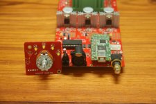
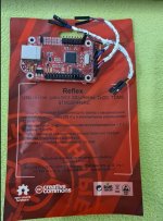
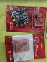
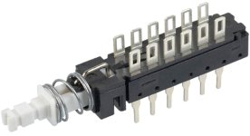
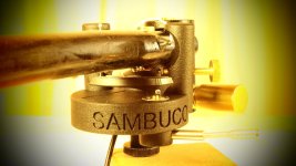
 I've included a photo of the backside of the potentiometer. I really hope anyone can help me with this


