Hi,
I've attached the section of a project that converts speaker lever audio to line level.
It's similar to many I've seen on the net except for one detail (which I got from a schematic I also found on the net): it includes a 1uF series capacitor.
Would someone tell me why the cap is there?
I've attached the section of a project that converts speaker lever audio to line level.
It's similar to many I've seen on the net except for one detail (which I got from a schematic I also found on the net): it includes a 1uF series capacitor.
Would someone tell me why the cap is there?
Attachments
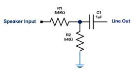
It's to protect the low level devcie from a fault on the loudspeaker output, and in case the low level device does not have an input capacitor.
If you know that it does, you could omit it.
If you know that it does, you could omit it.
thank you . . . what would you say is the attenuation of this circuit? Or am I adding apples and oranges because of the impedance difference?
The attenuation is (5600+540 )/540 = 11.37 times lower. So 11.37v RMS in gives 1V out. Or 20v RMS which is 50watts into 8r will give about 1.75v
But the input impedance of the following stage will affect this, unless it is much higher, eg >47k
What is the rating of the amplfier and input impedance of the low level device?
You could replace th 5k6 resistor with a 10k preset for a wider range of adjustment.
But the input impedance of the following stage will affect this, unless it is much higher, eg >47k
What is the rating of the amplfier and input impedance of the low level device?
You could replace th 5k6 resistor with a 10k preset for a wider range of adjustment.
Were I to replace the 5.6k with a 10K according to the arithmetic the parallel resistor would be about 965 ohms, yes?
If so, I guess a 1K would do.
I cannot tell from the MC33171 prod info what the input impedance is. (I've attached the sheet.)
I've also attached the "differential" section of my project. This section is used to eliminate whatever is common to both right and left channels of a stereo signal. It's my hope that (using the 250K tandem balance pot) voice will be suppressed.
I figure the input impedance will be altered by the use of the 100K volume and 250K balance pots despite what the MC33171 does for a living on its own.
Attachments
If you just want a fixed attenuation then no need to change it.
The 10k (linear) refered to a potentiometer which could double the attenuation to about 20times with the 540r resistor when on max resistance. At 50% the attenuation would ba about the same as with the 5k5 resistor.
The 10k (linear) refered to a potentiometer which could double the attenuation to about 20times with the 540r resistor when on max resistance. At 50% the attenuation would ba about the same as with the 5k5 resistor.
Thank you . . I'm actually am looking for as little drop as possible.
In a previous incarnation of the differential section I use an LM386 IC.
I found such a schematic on the net which included two 4.7uF caps inserted before the inverting and non-inverting inputs.
I've attached what it looked like.
Would you tell me what purpose those elect. caps serve?
In a previous incarnation of the differential section I use an LM386 IC.
I found such a schematic on the net which included two 4.7uF caps inserted before the inverting and non-inverting inputs.
I've attached what it looked like.
Would you tell me what purpose those elect. caps serve?
Attachments
- Home
- Source & Line
- Analog Line Level
- Use of capacitor in Speaker to Line Circuit