Need help trouble shooting JL Audio Slash 500/1 v1

So I went thru the common trouble shooting tips.

The amp powers on, voltage looks good at 14v with car on.

I am using signal sensing.

I measure the voltage from the speaker terminals and it normally works for a bit soon as I turn it on and after a little but usually less than a minute the sub no longer works but the amp still has power. I get the same behavior when I hook it up to the sub, it works for a bit and then no longer works. While driving it works intermittently.

I thought it may be something to do with the rca cables or the tap from the speaker wires, so I grabbed my iphone and plugged a 3.5mm to RCA and plugged it directly to the amp still did not work.

I opened up the amp and do not see any burn resistors or blown capacitors.

I know this is an old amp, just not sure if I should give up and buy a new amp or if this one can be saved. Any help appreciated.

MTX JH1200 repair

Good evening. Please help me with the repair of Mtx jh12000. He came to me without many complete sets and I am trying to restore them. Can anyone know what resistors should be in the allocated places? And another problem is + -15v. put new lm317 lm337 but they heat up even without load, 70 volts come to their input after tip29 tip30 ..
Tip29c and Tip30c I replaced with bd911 bd912 Did I do it right? I could not buy original spare parts in our city. I also attached a photo of the pulse on the shutters of the power supply, is everything good there? Thanks in advance to everyone who responds ...

Attachments

  • IMG_20201119_231119.jpg
    IMG_20201119_231119.jpg
    338.9 KB · Views: 133
  • IMG_20201119_231003.jpg
    IMG_20201119_231003.jpg
    410.7 KB · Views: 121
  • IMG_20201119_124540.jpg
    IMG_20201119_124540.jpg
    896.4 KB · Views: 149

Youngsters & Tomorrow's Newcomers in Jazz, Blues, Latin

2018 meditaçao JOAN CHAMORRO PRESENTA ALBA ARMENGOU & SCOTT HAMILTON - YouTube

Stumbling over this video again today inspired me to start this thread.

Joan Chamorro started this wonderful project, teaching the foundations of jazz to youths and young adults in Barcelona, and performing on stage in their band. In addition to rehearsal videos like this one, there are also concert videos in their channel.

Enjoy, and if you like share your own findings of possible stars of tomorrow!

Attachments

  • Joan Chamorro.JPG
    Joan Chamorro.JPG
    143.5 KB · Views: 82

Tapped horn sub chuffing too much

I built the Volvotreter 38hz folded tapped horn mini subwoofer. Tried the original Tang Band driver and also a Wavecor driver.
I built the double fold version:
https://volvotreter.de/downloads/TangBand_W6-1139SC_38Hz_TH_Rev_1.pdf
The Tangband 38Hz Tapped Horn – Volvotreter Homepage

The mouth of this tapped horn makes way too much chuffing noise. Using it 35-75hz.
It's a pity and I'd like to ask for help identifying the problem. Is it a bad design?
Can I increase the mouth opening, or modify it in some way to not scrap all the wood?

Any advice and thoughts on making this design work for me would be very appreciated.

CD player modding - Specifically my Denon DCD-820

Hi all,

I've recently acquired a lovely condition Denon DCD-820, as I was keen to see how the old 80s Burr Brown DACs compare to newer examples.

I'm thoroughly impressed with how it sounds - I can usually tell sod all difference between different DACs and players where modern equipment is concerned, but there's a definite difference here. I'm hard-pressed to say whether I actually prefer the sound using the Denon's onboard DAC, or my Audiolab 8200, but it's all good fun and it seems to vary depending on what I listen to.

Now I've read a few threads about people modding older players, and I'm wondering if it's something I should dabble in.

Is there anything I can do to it that will garner a real, noticeable difference?

I've read about things like removing muting transistors, re-capping, changing op-amps etc. The latter is probably beyond my capabilities as an amateur, but I'm interested nonetheless.

Will these changes make any difference, and/or introduce any drawbacks?

Anything else I should consider?

Thanks!

Proac Super Tablette Xover

Hi, I am new here. Recently a friend of mine bring his Proac Super Tablette to share this great little speaker. It was purchased some 30 years ago. So I took the chance to open it up for a look of what's inside.

Here is the Xover circuit in case someone want to play with it. I did the measurement for all 3 inductors and their DCR values are also included in the circuit.

https://farm8.staticflickr.com/7849/47239217361_3742d7eec2_b.jpg

R3,R4,R5 are DCR for the 3 inductors. Please do pay attention to L3 which has a 6R7 DCR. If you are trying to replace L3 the DCR has to take into consideration. 6.7ohm has a huge impact for the midbass around 1K~3kHz

happy DIY !

Crossover Review

Hi, as a method of learning, I was wondering if anyone with greater knowledge than myself could provide some feedback on this crossover design that I've been working on.

I've never designed or built a crossover before. Therefore I'm looking for pointers to understand if I'm on the right track (especially before purchasing components).

My main knowledge base for this design was the "Crossover Design Cookbook". To be fair its pretty much the same schematic, I'm just unsure if the application is working out the way it should.

So please let rip. It'll be useful to understand the good, the bad and the ugly.

🙂

Attachments

  • 20201201_2100.png
    20201201_2100.png
    181.2 KB · Views: 295

Placement of dualdiff/bridged amp boards?

I am doing a 2 ch 400w/4ohm dual differential bridged amp and it just hit me that there may be placement considerations on where in the enclosure to put them. My instinct and current plan is to put them as close as possible to each other and in as much of a symmetrical way I can, like shown in the picture.
Now looking at it I started thinking if this might be problematic with supply currents creating magnetic fields inducing more distorsion vs separating the amp boards and getting different cable routing and lengths.


Any experience, thoughts on this?

leuqAZE.jpg

12" PA drivers: Faital 12PR300 vs Eminence 3012_HO

Faital 12PR300 vs Eminence 3012_HO

Can anyone give me some feedback about these drivers? I want to use them from about 100hz-1500Hz in a vented cabinet. I've used the PR300 and I like them. Are the Eminence an upgrade? I see they have slightly larger Xmax and power handling.

The peaky midrange of the Eminence is a concern (Faitals are very flat there)
Can it just be EQ'd flat with good results?

Thanks.

Hum in Aleph J

My Aleph J is balanced (XLR). From XLR I have conected plus and minus to RCA. I use jumpers in the XLR connectors between ground an and minus.

When nothing is connected on input I get hum with jumpers.
Without jumpers it's quiet.

When I connect preamp/source its also hum with jumpers inside. But the strange here is that its becomes quiet if I only remove one jumper.

Can someone help me?

Is it necessary to use jumpers when I use rca connections. If I remove jumpers and only use plus and minus it will become quiet. I also think minus and ground will be connected in the preamp side. with jumpers it will be connected at the Alpeh side two, but is it necessary.

  • Locked
Transistor Based, Switched Capacitor Power Supply

This project has NOT been practically made and may not be soon, because of difficulties to home make this project and lack of equipment, such as an oscilloscope, etcetera.

This is, also, why I want to see the comments and the opinions of others.

A possible idea is to make an integrated system with a power supply, an amplifier, two speakers, etcetera, which, does not have any mechanical inputs and outputs, such as jacks, sockets, speaker connectors, potentiometers, etcetera, instead, everything is integrated and controlled by a remote control or through Bluetooth.

The same applies to the input signals, which are not mechanically connected to the system with jacks and sockets, but, instead, through Bluetooth only.

Because the system does not have any mechanical inputs, outputs and control, the case can be grounded to Ground and Neutral can be used as an internal, system ground. Thus, Ground will NOT be connected to Neutral, which means, such a system is as safe as a stove or power tools, even, safer.

The document was supposed to be very tiny, but, became still tiny, yet, not as tiny as intended. The schematics are in the addendum, so, please, scroll all the way with Ctrl Home.

Thanks for your help and advise!

Here is the document :

Transistor Based, Switched Capacitor Power Supply - Google Drive

Philharmonic Audio Affordable Accuracy Monitors + Center Channel

Excellent pair of Phiharmonica AA Monitors and Center Channel.

I will upload pictures soon - but 10/10 condition functionally, and probably close 8.5 or 9 out of 10 cosmetically. I believe the center channel is absolutely flawless, the monitors have minor scuffs on the bottom only due to placement on stands, otherwise no dinged/damaged corners, etc.

Don't know a fair price, but how about $185+shipping for the package? I can imagine another LCR that would even come close to this setup for the price.

Stax CA-X -> CA-X Pro. Is it a crazy idea - or not?

Hello all,

I am about to become the happy (?) owner of a Stax CA-X (and DA-80). The pair are functioning, and actually don't sound that bad, but I have plans...

At the very least, I'm going to replace the more perishable parts (electrolytics) and possibly the power devices on the DA-80, as suggested by EchoWars in a thread somewhere. So far, so good. And theoretically easy.

However, still thanks to EchoWars, I now have the schematics and parts lists not just for the CA-X, but for the CA-X Pro: different flat amp, with DC-servo circuitry. So I started thinking... what if I created a couple of "pro" flat amp modules?

The parts may be an issue to find: active devices are

UP07 / UN07 (low power JFET - g*d knows what to replace them with)
2SK117 (findable, though the two Idss grades may be an issue)
2SK150 (dual N-channel JFET - another unobtainium part?)

So, forum, two questions for you all:

1) Do you vote yay or nay? Do you think it's a completely crazy idea to recreate what is a nearly 40-year-old design? All the (very few) reviews and comments I have found seem to indicate that the PRO was significantly better-sounding than the already pretty good CA-X.

2) Do you have any ideas WHAT to use for the blessed parts above?

Thanks in advance for any comments and responses!

FabAudio USSA 5 with rare mosfet

4 modules available:

Assembled by Fab, the designer.

Mosfets 2SJ313/K2013
output Mosfets ALF16P16W/16N16W
Everything is matched.

They will be desinstalled from the chassis ; brand new ; Never never played.

The speaker protections from Mirand Audio are not included (separate listing)

US$180 each + shipping + 3% Paypal


If you prefer buying the complete amp, it is composed of : the chassis (custom), 6 speaker protections from Mirand Audio, 4 USSA 5 as described above, the PSU (SumR toroidal + VIFA bank for the USSA), Softstart Mirand Audio V1.1.
There are 2 modules TSSA V4 + 2 SMSP 600W but I cannot garantee the state of one TSSA V4 (something burnt part or fuse?).
It was assembled by Pinocchio ; top notch work and i would prefer that it be sold as one unit.

Complete amplifier : US$1300 + Shipping (very heavy) +3% Paypal

Attachments

  • image1.JPG
    image1.JPG
    819.2 KB · Views: 485
  • image2.JPG
    image2.JPG
    732.7 KB · Views: 489
  • IMG_20200328_103757_resized_20200328_104852032.jpg
    IMG_20200328_103757_resized_20200328_104852032.jpg
    271.4 KB · Views: 445
  • IMG_3128.JPG
    IMG_3128.JPG
    700.1 KB · Views: 450
  • IMG_20200401_221034 (1).jpg
    IMG_20200401_221034 (1).jpg
    83.8 KB · Views: 440
  • IMG_20200404_141921.jpg
    IMG_20200404_141921.jpg
    74.5 KB · Views: 218
  • IMG_20200404_142000.jpg
    IMG_20200404_142000.jpg
    141.6 KB · Views: 231
  • IMG_20200330_135431.jpg
    IMG_20200330_135431.jpg
    45.9 KB · Views: 232

electrostatic discharges

Im having issues with electrostatic discharges and electrical components. Right now in here is really dry and discharges are really often and strong. Last day I burned my potentiotemer because of a discharge after touching it for changing the volume and yesterday I was playing with a rotary encoder for channel selection and it got burned too. My question is: is there a way to wire the components to avoid burned all my components due to electrostatic discharges?

Fane 12-250TC or 15-300TC?

I'm curious to hear if anyone has done any comparisons between the Fane 12-250TC and the 15-300TC?


I have been looking around for short while for a larger wide range speaker (10"-15"), as I rather like the effortless and easy going/easy listening presentation that they can have. The Fane 15-300TC seems to be getting some good comments recently, but I was curious if the 12-250TC is comparable, sound quality wise? The 12" version is considerably cheaper, hence the question.


A pair of Rythmik subwoofers will be taking over the bottom end, so the wide range drivers do not need to do very low bass. I also have MiniDSP and a measurement mic, but it would be nice to do without the DSP if possible.


There are a couple of long threads that I have started wading through on each of these two drivers, but not a lot of subjective reviews. I will be listening to music through these 🙂 so was wondering what they sound like, if anyone has had the experience.


Any thoughts appreciated!


Cheers,


Matt.

Creek Destiny: Main Board Amp: Vgs Threshold on MOSFETs

Hello All,

I recently started rebuilding the amp section of my creek destiny using IRL2910 as replacements for the no longer available HUF76639 MOSFETS.
I'm trying to understand how VR2 and VR1 play into achieving Vgs threshold on the MOSFETs. If I'm understanding things correctly. I have the right channel working but I don't remember if I turned VR102 CW or CCW to slowly raise the idle voltage (across JP104) from .25mV to 1mV. (Thank you Mooly for that information in another creek destiny post). Does this happen when Vgs threshold is achieved at 1 volt? Which in turn enables VR101 to adjust the idle voltage to the desired 21.5mV? I am afraid of damaging components on the left channel if I turn VR2 in the wrong direction in the event VR1 won't adjust the idle voltage above .25mV. Is it CW or CCW?

Thanks for any help.
Best,
Gregory

Attachments

  • Screen Shot 2020-11-28 at 9.43.49 AM.png
    Screen Shot 2020-11-28 at 9.43.49 AM.png
    233.6 KB · Views: 147

a few pics of Karlson and K-tube

it might be helpful in some cases when using K-tubes on top of cabinets to experiment with a cardboard baffle at the driver's exit plane to perhaps get a better blend and support at the tube's iow end. If so, then a nice looking or transparent baffle could be made. It probably could be helpful to use felt on that baffle and also on the top of the low frequency cabinet (if one).

Inexpensive one inch compression drivers sound pretty good on K-tube the size of Transylvania Power Company's "The Tube" (1 inch diameter, ~5.3" long half ellipse based slot). No contouring of the highpass is generally needed.

Shallow K-cavities may work well with cone driver's having rising on-axis response. Look at XRK971's work with his little XKi cabinets. The .stl file shown is a tweeter lens by member Pelanj for Faital's 3FE22.

I believe apertures can be more narrow than traditional K when dealing with drivers having a lot of rise.

That K18 sounds very good imo.

When Karlson speakers are good and balanced, they can really be lots of fun and highly impressive.

I don't know who made the BLH and tube in this picture - - any clues? The slender
cabinet in the lower left is by Carl Neuser and employs a K-tube made of lamination
of maple veneer.

eOoQgrO.jpg


Weltersys;s Dad's K8 with Beta8cx, Carl Neuser's 1st HAK8 for Fostex Sigma 208 and Moray James
Karlson Quarterwave T-line are seen in this picture with some of my cabinets.


QrO9OxT.jpg


Z4Ipnfu.jpg


lapuWox.jpg


5AJtvVr.jpg

Cyrus 2 and Cyrus PSX - blows fuse in mains plug.

(Not quite sure this is the correct place, as there are no solid state components in these units, but Cyrus 2 posts seem to occur here (mod move if wrong place))

Well that day has finally come, and I'm rather sad, that my Cyrus 2 and Cyrus PSX combo have stopped working, I suppose it should not come as a great surprise, I purchased these in 1992, still have original receipts and box from Radfords HiFi (there's a name from the past!).

(these were the last of the Cyrus 2, Tog, Metal Case, and it's the last serial number on both Cyrus2/PSX) - also has a had written note in the manuals to this effect.

A little bit of background, although on a HiFi stand, kept very clean after moving in the last few years (well in fact that's 16 years), they've not been used until now, so I was surprised they still worked. and to be honest with you all this crap streaming and mp3 music I've been listeing two all these years, it's like I've been deaf (for 16 years) and re-awaken in the last 5 months, it was COVID-19, which brough me back to HiFi and listening to great music again. I just cannot believe the listening pleasure and audio/stereo seperations I'm hearing, Cyrus all the way here, with 782, 781 and 780. I listen to vinyl and compact disk, and also DAC via streamers and FLAC with a few DACs I have.

So the big question...... I recently read the review, which states Cyrus 2, not bad for it's age (and that was without a PSX)

Old amplifier vs. new amplifier: Which is better? | What Hi-Fi?

I know that to send these back to Cyrus, and get them serviced and repaired is £600. Which is ouch! but I only get 3 months warranty, but should that give me another 28 years worth of listening ?

But, I could purchase a Cyrus One, for £629 for new. That gives me 12 months....

But then I also read on the forums, that peoples opinion that I would have to spend at least £1k to get the same today ?

I did look at the bay, and prices for a working pair seem to be £400, or Cyrus IIIi £600-£700 - but what worries me with the IIIi is they are no longer serviable from Cyrus....

So what are my options ? What would you do ?

It's quite a difficult decision to say good bye to such old friends....

These were sold as a pair, and the Cyrus2 hads had the fuses removed, I was tempted to replace the fuses and power up, but thought maybe I should not do that... but then if it's going to cost me £300 for a serviced working unit, maybe I should.... I don't know...

but both are the same age, and maybe need servicing anyway...

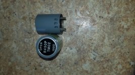
Again at present it's just when I toggle the switch, the light comes on for less than a second and goes off, and fuse in mains plug (3A) has blown.

Fuses in the PSX, and in the drawer are fine.

and this is also when connected and disconnected from Cyrus2.

Any ideas...

Thanks for reading my post.

A 3D printed part in my shoulder

It's a shoulder washer but not what you think.
In the pic you see the screw that holds the washer or shim, and the concave joint part fixed to the shim. The shim itself is invisible in the X-ray.
The ball joint part on the arm part is invisible behind the concave part.

They first made a 3D CT scan here in my Belgium hospital and emailed that to a US firm who used it to make the part. They replaced my right shoulder Monday.

Jan

Attachments

  • rechterschouder.jpg
    rechterschouder.jpg
    82.5 KB · Views: 309

New Music and Math Study Shows Strong Links

The paper: Multilevel Models of the Relationship Between Music Achievement and Reading and Math Achievement

Authors: Martin J. Bergee, Kevin M. Weingarten

And an article that explains the findings: New study shows strong links between music and math, reading achievement

Key concept: music and math probably share similar brain processes.

"Based on the findings, the point we tried to make is that there might be, and probably are, general learning processes that underlie all academic achievement, no matter what the area is. Music achievement, math achievement, reading achievement—there are probably more generalized processes of the mind that are brought to bear on any of those areas.

Therefore, if your goal is to educate the person—to develop the person's mind—then you need to educate the whole person. In other words, learning may not be as modular as it is often thought to be."

Need help to modify XO

My Harman Kardon Soundsticks have gotten flaky so I'm building some replacements per a thread on the Parts Express TechTalk forum Another salvo in the Micro-Monitor wars: The Dadiels -

Techtalk Speaker Building, Audio, Video Discussion Forum


I've assembled the XO's and drivers and listened, and the treble is rather reticent.

I'm guessing 4 - 5 dB more tweeter level will be in the ballpark; after that I can fuss with EQ if necessary.

Can I just decrease the value of the R2 padding resistor on the tweeter, or does that change the XO freq too?

Excerpt from post:

Try as I might, I could NOT get the phase to line up properly. I tried varying topologies, symmetrical, asymmetrical, 3kHz, 3.5kHz, on and on and on. No Joy. Either the FR was flat, or the phase was in line. Never both. So I left it alone for a couple of weeks. Meanwhile 50 Watt Head inquired about an improved crossover for the BR-1's. I told him that what he should do is take a look at the MurphyBlaster xo, but that I would take a shot at it. In the process of that, I got reacquainted with the Zobel network, and had a mini-brainstorm. "A Zobel! Why didn't I think of that?" So I went back into PCD, and entered a couple of random values as a Zobel, and immediately the phase came closer to lining up, and with a dip where there was a peak before! So, a little tweaking later, I wound up with the following crossover:

Attachments

  • xo.jpg
    xo.jpg
    32.6 KB · Views: 160

Options for integrating subwoofers in to my studio monitors without DSP?

Recently "downgraded" my studio monitors from Barefoot MM35s to Genelec 1032As. The MM35s are a sealed 3 way speaker with dual opposed 7" woofers, +/- 3dB at 35Hz. The Genelecs are a ported two way design with a 10" woofer. For most they would be great, but after the Barefoots, I miss the low-end.

I've decided on dual 12" sealed subs to match with the Genelecs. The subs I would most like to use (Rythmik L12) does not have a speaker output. It does have an LFE input, which to my understanding bypasses all the subwoofer processing, allowing for external processing. I'll be crossing over around 120Hz to smooth out a big dip related to floor bounce at my listening position .

I found this an option for external crossovers but I don't know if it's a decent piece of kit. Looks like it sells for around $250 USD.

I know there are DSP options, but I'm mildly old fashioned. The Barefoots were the first monitors with DSP crossovers I've used, and something always sounded fake/foreign to me.

Any input would be greatly appreciated!

Harmon Kardon Citation 22 repair/rebuild worth it?

So my Harmon Kardon 22 was working well before being out into storage for a couple of years (3 years maybe). Pulled it out of storage to hooked it up only to find it goes immediately into protection as soon as it is powered on, with or without speakers connected.

A bit of research has lead me to believe that replacing the 33uf10v capacitor on the protection circuit (c11) would be a good place to start.

I would like to learn more about troubleshooting this amplifier though rather than just following internet advice. Measuring voltages, other caps to replace, adjusting the bias. Where is a good resource for learning this?

Also is it worth putting time and resources into this amplifier? How does it hold up today?

LDR pre things

Cleaning up a wee bit and I find these LDR Pre thingy’s. This all aside the two matched LDR, came from I think ZDR (find the thread and it’s the chap that’s leading the path). I did use the built up unit for a short while (on a bread board for the TV as my wife is awesome 👏). I can’t recall what I paid for any of this and no idea it’s worth, I have far more preamps than any saine person so will never build / finish them.

First come (PM) first serve, you might want some or all of it. Price ummmm, well ummm swaps? Tell me you’re a poor student but can starve for a day to cover postage. Or tell me you’re rich and would like to trade me for your Jet.

Attachments

  • A9D7AD6A-665F-4ECB-8139-69B82C9280D3.jpg
    A9D7AD6A-665F-4ECB-8139-69B82C9280D3.jpg
    972.1 KB · Views: 201

Near field sub with far field mains

A bit of a thought experiment at the moment with not much else to do...
I'd like a sub, but live in an apartment and don't want to annoy the neighbours
I thought I could have near field subs, probably behind the head cushions on the sofa, or with a slot exit behind the sofa near head height

The mains are approx 4 meters away, so if the subs are 0.5m away from my head, they could be approx 18dB quieter

If they were too close, any head movement would change the sound level too much, and too far away would need too much output for the neighbours, so there's going to be compromise. Also, they wouldn't add much if walking around the room, but since I'm mainly thinking about movies, this wouldn't be an issue

The mains are flat to about 50Hz and another octave would be nice

Any thoughts please? Thanks

Brian

Add pre-amp outputs to AVR (Sony STR-DN1080)

Hi,

I have a SONY STR DN-1080, which I am mostly happy with it regarding the sound quality (and not much else).

The thing is I would like to add a preamp output to my receiver to connect them to a DSP and after that an ICEpower amplifier.

I have a few options, and I would like to hear your suggestions/opinions:

1-. Buy an HDMI Audio Extractor with 5.1 or 7.1 outputs like this one:
Kebidu 5.1CH HDMI Audio Extractor decodificar Coaxial a RCA AC3/DST a 5,1 amplificador analogico convertidor 4 K 3D para PS4 DVD-in Cables HDMI from Electronica on Aliexpress.com | Alibaba Group

I would use the secondary HDMI output on my receiver and would have to enable the output AMP+TV option. That way I don't need the HDMI extractor to be HDMI 2.0 nor compatible with 4K or HDR, just good enough to send/convert audio signal.

The problem is that the DAC inside this box is probably garbage and I will loose a good chunk of SQ.

it seems there are better products like these:
Monoprice Blackbird 4K Series 7.1 HDMI Audio Extractor - Monoprice.com

HDMI LPCM 5.1 7.1 To Analog Surround Decoder

But they may be based on the same DAC. There is no much info about them.

2-. Another option is to get a miniDSP nanoAVR HDA like this:
nanoAVR HDA

The only problem with this is the price... I know it's a much better product but it cost as much as my receiver (which I probably can ditch If I get this)

So, what do you think? Is there any better solution between those? Maybe an HDMI to pre-amp with a good DAC without DSP¿?

Oh, and please my friends, don't recommend me to switch AVR to a better model/brand as it is not possible right now.

Thanks!

Threshold S150 with E Series upgrade purchase

Purchased a S150 and realized that it has the e series upgrade done with balanced inputs and optical biasing. Amp is clean, quiet, and both heat sinks run within 2 degrees of each other, right around 100 degrees after an hour.
Dc offset is 28mv in one channel and 52 in the other.
What can anyone tell me about this amp? Biasing? Schematic, maintenance, upgrades? Amp runs cooler that i believe it should, can keep my hand on the sink forever.

Thanks in advance for any information.

Full range driver and flush mounting

I have built a pair of speakers using 5-1/4" driver (Tang band W5-2143). The driver is currently flush mounted (actually protruding slightly at about 1mm or so).

But cosmetically I am a little unhappy with how they turned out.

I am thinking of gluing a plank of solid wood on top of the baffle, rounding off the edge of speaker hole and the outer edges. This would make the driver mounting recessed. I've read that this is a bad idea for tweeter due to diffraction, but what about for 5-1/4" full range driver?

Protel 99 se file openning issue

Hello I am stuck with an issue which I hope someone here may have some advice on. I have been using Protel 99 se Service pack 6 for a while with no real issue. Now suddenly it is refusing to open any project files.

Sequence of events are as follows:
I open Protel
I click File - Open
Select the project file I wish to work on.
Click Open...

The open window closes and then nothing happens as if I had click cancel. I have tried creating a New project but then the program just crashes and becomes non responsive.

I am running Windows 10 Pro.
I have tried uninstalling and reinstalling.
I tried a system restore (which worked in the past) but that is failing to complete now.

If you need any further details please ask and I will try my best to answer them. Has anyone had this issue before? or have any suggestions of how I might fix it please? Any help would be greatly appreciated it.

Realisitic 2 Electrostat Crossover Help

Disclaimer- I'm pretty green at working with caps, etc. This is a "learning" project.

Hoping someone could help me identify a part on the crossover for Realistic Electrostats. There are approx 3 versions of this crossover and most of what I can find deals with a later version.

Mine has power issues to the electrostats which seems to be common. The solution is to replace the diodes. However, I'm not exactly sure what to replace them with as they don't seem standard. The board is marked Se/1MΩ, the actual part is marked "SM". See link below for pics:

Realistic Electrostat 2 Crossover - Album on Imgur

I'm hoping some of you could help identify what type of diode this is and go even further by explaining why the design looks so different.

Thanks!

[Advice Needed] DAC Balanced output filters + Gain stage

I want to add balanced xlr outputs to my DIY CS4398 DAC.
I am honestly a little clueless in my design choices, so any advice would be appreciated.

Mainly: Is this the right way of doing balanced volume control using opamps?

Secondary: I plan on adding a relay to pull the signal to ground to mute (see the flags labeled 'mute' near the volume control pot). However with this method will leave the signal trace on the pcb open when not muting and I'm worried it will work as a nice little antenna for EMI.

The output filter stage is taken directly form the CS4398 datasheet.

I've also added a screenshot of my current progress with the pcb layout. Something got messed up with the component annotations, so these might not correspond with the ones in the schematics.

Attachments

  • output filter.PNG
    output filter.PNG
    33.1 KB · Views: 173
  • Volume and Buffer Stage.PNG
    Volume and Buffer Stage.PNG
    35.1 KB · Views: 155
  • image_2020-12-01_175359.png
    image_2020-12-01_175359.png
    300.6 KB · Views: 144

Output ground to psu gnd?

Ive read that you should tie the output of a preamp to a signal ground along with the input ground and lift that with 1ohm resistor from the psu ground. Im wondering if the same should apply to headphone amps. Because if low ground impedance and power transfer is priority, i feel that the output gnd should be tied to psu ground, much like a power amp.

Which is the better arrangement and why?

Any Maplin MosFet Amp Guru's on here?

Just finished refurbing my original 1980's Maplin MosFet Amps, 2SK133 - 2SB48, Fitted in new case etc....

Before installing them in their final resting place, I ran them up on a +/- 15v supply, just to make sure they were working ok.

Today came the day to run them up on the full supply, after setting the Bias Current (50ma) is the figure I have for these.

All checked out ok, and with about 10mv dc on one amp and 14 - 15mv dc on the other.

My initial goal was to run them up slowly in 5v pk-pk steps, I only got to 15v pk-pk when I realised the OP Transistors were very hot, and by that I mean holding a pinky on one of the transistors started to get very uncomfortable after about 10 seconds.

I thought I had provided adequate heatsinking, after all, I'm using the original heatsinks I used from when first built them many years ago, and they gave me years of trouble free operation, but at that time I didn't have access to a signal genny or scope, and being in my early 20's I just boxed them up and away we went.

In the configuration I now have, I have used the case side, which is 3mm thick, and the Amps are bolted through this to the Heatsink with 3 x 6mm bolts, which is 190mm long, by 80mm High, with 14 x 5mm thick 40mm Fins, couple this with the side panels which are 90mm High and 290mm long / deep, and that's quite a lot of metal to heat up.

The one thing I did notice, is that over the years the Heatsinks have bowed very slightly, so there is a very small gap at the front and rear between the heatsink and case side.

I couldn't find my Thermocouple's at the time to see exactly what temperature the transistors got to, but I have found them now, so will take some readings tomorrow, ummm Later today now !!

As the heading implies, is there anyone using one or a pair of these amps at the moment, or carried out tests with a sine wave, and noticed they generally run pretty hot, or am I going to have to rethink my mounting method, and possibly drill and tap some more holes at the ends of the heatsinks which I have just had sand blasted and resprayed:Ohno:

Anyone build a Weber 6M18VIB (18w Marshall clone)

After successfully building a number of tube and solid state studio devices, I'm attempting to build a Ted Weber 6M18VIB ( 18w Marshall Clone ) combo kit.

I'm unsure of how to exactly wire the input channels and wondering if someone may be able to confirm and / or assist with clarification.

After reviewing the provided build layout and associated schematic, the attachments here are my best swing at completing wiring configuration.

Any thoughts or comments will be greatly appreciated.

Thanks in advance!

Attachments

  • 6m18vib_input_diagram.jpg
    6m18vib_input_diagram.jpg
    271.7 KB · Views: 153
  • 6m18vib_schem.jpg
    6m18vib_schem.jpg
    512.8 KB · Views: 171

Hafler Transnova 9300

Please forgive me if I am going about this incorrectly. I am new and this is my first post.
I recently purchased a Hafler Transnova 9300, this amp was stored for 15yrs due to the death of the previous owner. Internally it appears in excellent shape, it sounds great. I have searched the net and dont find much info.
I would really like the following:

owners manual PDF
Service manual pdf
Specs
Comments from anyone on any valid info on the amp
Copy of the magazine review on it, or how to go about obtaining it.

Worth getting a USB DAC for laptop if I only listen to internet radio?

I'm sure this has been asked already, but I've googled for a half hour w/o finding an answer.

My HK Soundsticks have gotten flaky so I'm going to replace with better speakers (I hope, the Soundsticks sound pretty darn good), amps, and subwoofer.

If I just listen to internet radio (mp3 I think), will I get an appreciable improvement in sound quality over my laptops 3.5mm analog output?

Noise isn't a problem now, perhaps because I've lost a lot of high freq hearing.

So the improvements would need to be in the areas of general cleanness and clarity.

Scanspeak Mids and Tweets

Bought these new from Madisound in 2016. They are new in the boxes. And when I say that I don't mean except for that one time I hooked them up or when I test fitted them. They have never had a wire attached or even been taken out of the boxes other than looking at them and taking pictures.

I've got 4 12MU/8731T00 mids.

These were supposed to go in a WMTMW of my own design but life happened and I don't know when I will have a place to use the monsters I was planning to build.

I'll sell as a package or in pairs, no singles. Shipping within CONUS included in prices. Or you can pick up in the Atlanta area.

2 X 12MU - $450 Shipped

4 X 12MU - $850 Shipped

Attachments

  • ScanspeakMids1.jpg
    ScanspeakMids1.jpg
    173.9 KB · Views: 1,031
  • ScanspeakMidsBox.jpg
    ScanspeakMidsBox.jpg
    212.2 KB · Views: 1,023
  • ScanspeakTweets1.jpg
    ScanspeakTweets1.jpg
    204.2 KB · Views: 1,010
  • ScanspeakTweets2.jpg
    ScanspeakTweets2.jpg
    202.6 KB · Views: 993
  • ScanspeakTweets3.jpg
    ScanspeakTweets3.jpg
    209.2 KB · Views: 973

LTSpice THD in error report second result

Two questions as I try to remember what I forgot in the last 10 years:
In the error report, for each of the two nodes I listed, it provides as I requested, all 9 harmonics and a total, But there is a second value in paren. What is this value?


N-Period=all
Fourier components of V(vout)
DC component:-0.0021609

Harmonic Frequency Fourier Normalized Phase Normalized
Number [Hz] Component Component [degree] Phase [deg]
1 2.000e+04 2.978e+01 1.000e+00 -5.44° 0.00°
2 4.000e+04 2.388e-04 8.019e-06 -54.43° -48.99°
3 6.000e+04 7.264e-04 2.440e-05 -156.21° -150.76°
4 8.000e+04 1.038e-05 3.486e-07 25.32° 30.77°
5 1.000e+05 8.032e-05 2.697e-06 -77.23° -71.79°
6 1.200e+05 3.249e-05 1.091e-06 -26.49° -21.05°
7 1.400e+05 5.559e-05 1.867e-06 16.90° 22.35°
8 1.600e+05 1.800e-05 6.046e-07 -4.94° 0.51°
9 1.800e+05 1.520e-05 5.103e-07 138.94° 144.38°
Total Harmonic Distortion: 0.002593%(0.014511%)


Second question. Running current version XVII October 2020. Be darned if I can find the function that displays the spectrum. Not in the view traces. Do I have something turned off or hidden?

  • Locked
FS: The Wire headphone amp kit - box of parts

I have a box full of parts that I had purchased years ago to build several versions of The Wire headphone amp and associated power supply that was designed and offered here by Owen (AKA opc):

The Wire - All Boards and Kits Explained Here!

I neither have the time or desire to go through the box and attempt to inventory and list all the individual parts let alone attempt a build. I can not honestly say this kit is complete. Assume it is not! I can say that I have at least the SE-SE, BAL-SE and PSU V1 pcb's, plus another 5 related Wire pcbs I can not identify. I believe MOST of the component parts for the builds are included but it's not guaranteed - Including heatsinks and some hardware like small SS screws nuts spacers. Be aware that some components in this kit may be discontinued and no longer available anywhere at any price!

I am willing to ship the entire box of parts AS IS to the CONUS lower 48 for $35 via paypal. If not you then it's the landfill. Please PM if interested - Thanks for looking!

PS tube rectifier question

I have completed a 5E3 build and was going to follow up with a CJ11. The schematic for the CJ11shows a center tapped 5V winding for the GZ34 rectifier, with the HV coming from the center tap. On the 5E3 there is no center tap on the 5V winding, and HV is taken from Pin 8 of the 5Y3GT rectifier. The CJ11 PS transformer HV is 290-0-290, while the 5E3 is 355-0-355.
I believe I understand the differences of the 5Y3 vs 5AR4 (the construction,voltage drop, and current).
Is the center tapped 5V used to have less AC filtering (2.5V vs 5V) on the HV? Or lower HV?
My PS transformer (290-0-290) does not have the center tapped 5V. Would it be safer to substituted the 5Y3 and take HV from Pin 8?

Attachments

  • CeeJayEleven.jpg
    CeeJayEleven.jpg
    142.2 KB · Views: 124

EL84 tube amp build, how to start?

Hi I'm Jona and tube amplifier building is all new to me, so please bear with me.

I have always had the dream of building a tube amplifier for regular llow level music playing, so some time ago a received some older tube amplifier radio's. From them I sourced

2 mains transformers, 4 output transformers
and the following tubes for preamp with socket:
12AU7: 5
12AX7: 3
12AT7: 1
ECC85: 2

and then 4 EL84 tubes with socket for the power amp

So now comes the question. How would I go from here to build an amplifier. I have found some schematics using these tubes but I don't know which one I can use with my transformers.

So I think at first I need to know what type of transformers I have to continue?

Also should I go for a class A setup with the EL84 or use them in class AB.

How can I test the tubes to see if they are working.

Thanks in advance.

PS: I also got these tubes if they would be useful:
6AU6, 6BA6, 6BE6, ELC86, 6AB9

Thorens TD124 - Suggestions for tonearms that fit without modifications?

Hi there everybody.

I have my TD124 working with an AT-1501mkIII that I spent a lot of money for. I also had to purchase a new plinth so I could ream a hole out of it to provide clearance for the main tonearm post. I'm not a woodworker, so it wasn't easy.

I was thinking I'd like to use that arm on a different turntable I got running, which is kind of floating my boat right now. So, I'm trying to find a tonearm that will fit with the proper geometry in the TD124 chassis and armboard without modifications or drilling large holes in the plinth.

The standard size armboard is designed to accommodate shorter tonearms. According to vinylengine.com, the Thorens TP14 arm had a pivot-to-spindle distance of only 190mm (with 20mm overhang). That's really short!

Therefore, my question is:

- What tonearms are you TD124 users out there using that fit easily on the standard armboard? Everybody's using SME 3009?

- I had been using an Audiocraft AC-3000 tonearm with 222mm pivot-spindle distance. That works. The problem is that it's an oil-damped unipivot, and I'm tired of fiddling. When it sounds good, it sounds great. But I've gummed it up with leaking damping oil, and it's a bear to get working correctly, and I have a tendency to gum things up. I think I need something that's more fool-resistant.

- I had purchased a Sony PUA-7 tonearm for its 222mm pivot-spindle distance, which looked like it would fit just fine. The problem is that its mounting collar is so wide it won't fit on the armboard without intruding onto the (raised) metalwork of the turntable. (See photo.) It's so frustrating.

- I also purchased an Audio Technica ATP-12T, thinking I could use the larger version armboard. But no, if I place the tonearm at the proper pivot-spindle distance, the arm post comes down right on that metal bar going around the perimeter of the armboard. Frustration again.

- I was looking for an Audio Technica AT-1005 or AT-1009, but have you seen the prices on eBay for these things? It's nuts. Too bad, because I'm sure one of those would fit easily (225mm pivot-spindle).

- Is the least expensive Jelco SA-250 tonearm (~$470) up to the standards of the AT or SME 3009 tonearms? Or does one have to spend the $700+ for the higher models to get to that level? (I understand the 1960s-70s AT tonearms had very good bearings, and I know a lot of people think the SME 3009 was very good.)

If I find an AT-1005 or AT-1009 in good shape for reasonable $$ then I'll go for it. Or maybe I'll come into some money so I can shop for anything I want. But for now, the question stands. What tonearms are you TD124 fans using that mounts easily to the stock armboard, and that you believe perform very well?

Thanks.

Attachments

  • Sony_PUA7_tonearm.jpg
    Sony_PUA7_tonearm.jpg
    628.8 KB · Views: 279

Aliens having Tube Amp Concert in Utah

Looks like they prefer Stainless Steel tube amp chassis or speaker cabs.
Where can I buy one?
Metal monolith found by helicopter crew in Utah desert - BBC News

"It is illegal to install structures or art without authorisation on federally managed public lands, no matter what planet you're from," the department said.

Helicopter crew not wearing face masks. Bigger violation!

Attachments

  • Rapa_Nui.jpg
    Rapa_Nui.jpg
    15.4 KB · Views: 662
  • Monolith_Utah.jpg
    Monolith_Utah.jpg
    87.7 KB · Views: 663

FS: 2 pairs of Philips 9710 full range

Prices:
170e including shipping for alnico
130e including shipping for ferrite

The location of these is Finland. I can send these basically anywhere in the world. Swap for AB-amplifiers or other speaker drivers is also ok, I trust the people here know the price range of these 🙂

I'm clearing up my audio stash. Among these are two pairs of Philips 9710 drivers, one with alnico magnets, other with ferrite magnets. The alnico is an older production run pair, made in 60s I believe, while the ferrites are made in mid/late 70s. They were pulled from swedish-made Carlson cabinets, the earlier pair from OA-4 (different production run, so gasket is slightly different color), and later from OA-5 (pair matched in factory).

I don't have measurements for these speakers, but I listened to drivers on a blind test on a crude plywood OB test A vs B and couldn't spot differences. To my ears, it tells specs are pretty close to each other

Here are pictures of the speakers:
iCdODR1.jpg

jephwse.jpg

tN4ofri.jpg

5FEbic0.jpg


On the older pair, there was a small tear in the surround for each. It has been fixed with with diluted PVA glue and very thin paper and tested for leaks. The fix has no effects on sound quality, but the crack will still show on the outside. The color is not 100% the same on the cones, the one on the right has been in sunlight more and is slightly more faded. Also between production years in 60s, it seems Carlson decided to paint the gasket black, so there is a difference in gasket color as well. To my ears, the alnico sound a bit more "lively" than ferrite pair.

The newer pair is factory matched, was on the same owner for almost 40 years until I purchased them off. The cones are 100% color identical. There is a small droplet of black paint (or nail polish, not sure) on the cone on the right. You might be able to flick it off with pincers, but I haven't tried. You can see it in the picture.

So long story short, if you are interested sent me a PM.

Hornsrep input help for kick bin.

Hi all, can someone help me with the hornsrep inputs, my maths is terrible plus I’m not 100% sure how to work it out in the first place. Im comparing these 3 designs and already know witch one I prefer standard, but I would like to make these 3 designs narrower and the same depth and height to see what the differences are, before I go ahead and build. I want to keep everything else the same internally just changing the external dimensions.

I want the external dimensions to be : 686mm High, 500mm Wide, 721mm Deep

If someone could do a screen shot of the input page with the changed inputs or a list of the correct inputs I would be massively appreciated.

Designs are below hopefully.

Thanks luke

Attachments

  • 812451DC-B0A4-48DC-AEF8-D351F7A5E3B5.jpeg
    812451DC-B0A4-48DC-AEF8-D351F7A5E3B5.jpeg
    131.6 KB · Views: 155
  • 14D9C84D-3E71-4DB2-9549-C4EB481D7847.jpeg
    14D9C84D-3E71-4DB2-9549-C4EB481D7847.jpeg
    397.7 KB · Views: 135
  • 6226534C-5D46-44E0-85B4-061682EBDDF1.jpeg
    6226534C-5D46-44E0-85B4-061682EBDDF1.jpeg
    373.2 KB · Views: 130

push pull EL84 amplifier cathode bias question

I am reviving an old WEM guitar amplifier which has push pull EL84s in what is rated (optimistically I thought) as an 18watt effort. It is a conventional setup where the EL84 anodes are directly connected to the OP transformer while the screen grids run from HT via a 1.5K resistor. The EL84 cathodes are commoned to ground via a single 100R bypassed by 50uF. To avoid having to use matched EL84s I would like to institute separate cathode biasing. My question is should I merely duplicate the existing for each valve or should resistor values be changed? I am afraid I do not really know how to calculate this and would be grateful if it could be explained. Thank you.

Fostex FF165WK Planet 10 Drivers and stock FE206E drivers

Selling 2 pairs of Fostex drivers:

  1. Fostex FF165WK drivers modified by Planet10 (EnABL'ed) - asking $175 obo
  2. Fostex FE206E drivers, NOS, stock - asking $180 obo


The Fostex FF165WK drivers are used but in good condition.
They were modified by Dave Dlugos of Planet 10 audio with his EnABL'ed process, and I purchased them second hand.
Just too many projects and I'm clearing some things out!

The FE206E drivers are NOS, in original boxes, and have never been used.

Thank you!
Tom

Attachments

  • Fostex_Planet10_FF165WK_001.jpg
    Fostex_Planet10_FF165WK_001.jpg
    599.3 KB · Views: 195
  • Fostex_Planet10_FF165WK_002.jpg
    Fostex_Planet10_FF165WK_002.jpg
    713.5 KB · Views: 184
  • Fostex_Planet10_FF165WK_004.jpg
    Fostex_Planet10_FF165WK_004.jpg
    813.4 KB · Views: 192
  • Fostex_Planet10_FF165WK_006.jpg
    Fostex_Planet10_FF165WK_006.jpg
    513.4 KB · Views: 186
  • Fostex_Planet10_FF165WK_009.jpg
    Fostex_Planet10_FF165WK_009.jpg
    389 KB · Views: 183
  • Fostex_Planet10_FF165WK_010.jpg
    Fostex_Planet10_FF165WK_010.jpg
    345.9 KB · Views: 79
  • Fostex_Planet10_FF165WK_011.jpg
    Fostex_Planet10_FF165WK_011.jpg
    621.2 KB · Views: 64
Projects by fanatics, for fanatics
Get answers and advice for everyone wanting to learn the art of audio.
Join the Community
507,753
Members
7,886,666
Messages

Filter

Forum Statistics

Threads
406,157
Messages
7,886,666
Members
507,753
Latest member
ayodej