Mislabeled Stk amp?

I just need some help to figure this out.


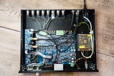
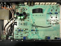
I have a old sony system with what apears to be labeled as a STK 4182 II amp that is rated at 80w + 80w @ 10%THD but when I search the chip model I get a 45w + 45w @ 0.4%THD Chip whats up with that I just want to know is the chip mislabeled because I did tests and I get 80w RMS sometimes I get close to 130w RMS when going into clipping So please just a little help I'm still new to all of this

Yet Another SSE Build Thread

I am guessing that the regulars around here, maybe even George himself, have become a bit bored with these SSE builds. I mean really, how many years has it been?

On the other hand, for people like me this is new and exciting - and I have really enjoyed reading other people's build threads. So I figured I would post my journey.

So far, I have obtained the board and sourced all the minor components, built the board, and have some of the major components - with the rest on the way.

This is what I've decided:

- "Inverted" orientation for under-chassis mounting
- Current inrush limiter on mains primary
- Hammond 274BX
- C1 = Nichicon 47uF 500v
- C2 = Kemet 150uF 500v
- Triad C14X choke
- Kemet 80uF 470vac PP motor run cap
- TR1, D3 and D4 installed
- Binding posts installed for C11/21 and R17/27 to enable easy replacement
- CDE 942 series PP coupling caps C11/21
- 680ohm to start off R17/27 (plan to run EL34 exclusively for quite some time)
- a selection of various other values for R17/27 for future use
- Gold-plated copper inputs and speaker terminals
- 18GA 600v 200C tinned copper silicone hookup wire
- probably DIY chassis - typical wood frame and aluminum top
- not 100% decided on OPTs yet - have some cheap Chinese ones on the way just for testing
- Tubes will be EH EL34, NOS GE 12AT7, and various rectifiers (Shuguang 5AR4, NOS RCA and Sylvania 5U4GB).

Photos of progress so far:

(Note: the way I have oriented the C11/21 and R17/27 binding posts may seem odd, but they make component installation/replacement easier (for me, anyway).

attachment.php


attachment.php


attachment.php


attachment.php

Attachments

  • 2020-02-05_14-37-20_806.jpeg
    2020-02-05_14-37-20_806.jpeg
    199.6 KB · Views: 2,028
  • 2020-02-05_15-02-37_466.jpeg
    2020-02-05_15-02-37_466.jpeg
    320.8 KB · Views: 1,205
  • 2020-02-05_16-34-59_295.jpeg
    2020-02-05_16-34-59_295.jpeg
    408.6 KB · Views: 1,192
  • 2020-02-05_16-35-54_468.jpeg
    2020-02-05_16-35-54_468.jpeg
    454.5 KB · Views: 1,240

Different headphone amps

The schematic of this headphone amp is attached.

It is different because:

1. It uses Class aP amplification. It switches analog [music] signals via precision rectification to generate analog Pulses [aP].

2. It is a current source amp.

3. The normally-shared ground lead of stereo headphones is separated so to cater to each headphone. Needed with any current source amp!

4. A common [+/- 15 V] is used for both channels, and an additional +/- 9 V [or higher] for each channel. All 3 supplies are very low power; preferably regulated.

The above may sound complicated; but the prototype sounds fine despite its switching operation.

The schematic is an image of a simple LTSpice file. Examine performance at the circuit points which are enclosed in rectangles.

Please find the thread "Class aP amplification" in the Pass Labs Forum for additional info.

Best
Anton

Attachments

  • ClassaP current source headphone amp.png
    ClassaP current source headphone amp.png
    37.5 KB · Views: 1,046

SLP-90 Power Supply

Attached is the B+ supply for Cary Audio's SLP-90. It is als0 somewhat similar to subsequent model SLP-94, SLP-98..

The strange thing is the rectifier feeds into extremely brutal CRCRC stage (560uF-22k-560uF-22k). If i run this in PSUD, it gets all sorts of red flags, including high current, high PIV etc.

But the preamp seems to be running well and there is no complain about premature rectifier life.

What seems to be the trick here?

Attachments

  • SLP-90 Power Supply.jpg
    SLP-90 Power Supply.jpg
    74.1 KB · Views: 284

Rotel RB-960BX Crackling Intermittently

Hi This may not be the correct thread but Iv only just joined. I have a Rotel RB960BX, and it has started to crackle intermittently, Iv have traced it to the right hand side of the power amp, Iv cleaned the speaker posts and cannot see any obvious problems, (bad soldering damaged tracks etc) I read that the caps can fail, any help and advice would be great

Bridging two push pull power PCBs help!

Hey Y'all,

I’m currently buying components for a KT100 run power amp, which I will have someone else build due to my non qualifications with tube / high voltage technology. However, I still want to buy all of the components necessary for him to build it, while learning how the parts I’m buying work. I’ve recently settled on a couple stereo push pull pcbs (I haven’t decided which I’m buying yet), that are able to be bridged from two 80w+80w channels, to one 160w channel.What was wondering if is if it would be possible to take it a step even further...Would it be possible for me to buy two copies of whichever PCB i chose, and have the two bridged channels bridged again, combining the two 160w pcbs into channels into one 320w channel?

Here are the two PCBs I wanna buy…

Williamson push-pull Amplifier circuit board For 12AX7/12AU7/EL34/KT88/6P3/6L6 | eBay

Stereo Push-pull 12AX7+12AU7+EL34 Vacuum Tube Power Amplifier Board Bare PCB AMP | eBay


Anything helps!

High power Germanium power amplifier (any thoughts??)

I dont think anyone has been in my situation more of because these very high power germanium transistors are kind of a rarity and there is not many of them at all..

I got a hold of a factory matched pair TESLA 7NU74. TO3 style 50W PNP transistors. Uce 70V with a Rbe of 30 ohms at least thats what the datasheet states (yep thats right none of that low residual current silicon rubbish).

I couldnt find ANY high power germanium amplifier schematics. What I plan to do is salvage a well known silicon based amplifier schematic and adapt the power output section for the 7NU74s (PNPs) unlike for the bootstrapped NPNs.
More likely I will avoid any feedback.

I will use silicon semiconductors for doing the preamplification and the drive and the bias (transistor diode bias). Ill be using BD139,BD140 to do the driving of the finals (7NU74) and probably do some easy preamplifying stage with a BC547 and a current source so I have stron signal going to the drivers aswell. At least thats what is my plan

If anyone has a actual schematic that would be a high power germanium amplifier (30W and so on) I would appreciate if you would show it to me and let me know your thoughts and ideas on this. I have not come up with a schematic yet, but its on the list of things to do.

Specs of the granny tranny:
-Ucb: 90V
-Uce: 70V (with the 30ohm Rbe)
-Ueb: 15V
-Ic: 15A
-Icbo max: 1000uA
-Ucb: 6V
Hfe: 50-130
Ie: 10A
-Uces max: 1V
Ft: 150kHz

Got a little tired of looking at the transistors in the box so I want to do some adventure stuff with them 🙂.

Edit: I have no intentions in using any kind of iron in my build. No transformers beside the power supply.

Confounded by left main amp board in Rotel RA-1412

A non working Rotel RA-1412 came into my possesion in October. Since then, both power supplies were made to operate normally. Next I intended to check the DC adjustment and bias but ran into a problem or two that I cannot sort out.

Firstly, moving the bias adjustment pot of the left main amplifier board either way does nothing, the meter continually reads 0 milivolts. There are three adjustment pots on each amp board. I removed and cleaned the three on the board in question but no change, rotating the bias adjustment still produces 0mv on the meter display.

Bias on the right channel main amp board is adjustable.

Secondly, the Protect LED lights up unless I disconnect +B and -B from the left main amp board. After that, the amplifier comes out of protection and the right channel operates as it should.

My thought was of a defective component on this left main amp board.

So far I have removed and checked every transistor (some more than once), the one and only diode, measured every resistor (replaced two that were quite under spec), removed and replaced the four electrolytic capacitors, examined the foil side for any solder bridges or bad connections. And as mentioned, removed and cleaned the three adjustment pots.

For what it's worth, the device I have for checking transistors is one of the cheap inexpensive multi-testers from China. It has previously identified bad transistors as a "diode" or "unknown device". All of the transistors on this amplifier board were identified as BJT so by virtue of that, I accepted that they are all OK.

Nothing seemed wrong but connecting that board continually makes the amplifier go into Protect Mode.

What I did next may be thought as silly but it's all I could think of. I have no bench euipment at my disposal.

With power going to the board, I disconnected each and every wire individually to see if disconnecting one of them prevented activating the Protection circuit.

And one of them did - the wire going to pin #5. Which looks, coincidentally enough, like it feeds into the Protection circuit board.

I have yet to expose the Protection circuit board because I cannot dismiss the notion that there is something about the left main amp board that is causing the problem.

If any tips or suggestions come to anyone's mind, they would be appreciated.

I realize that no one here may be familiar with a Rotel RA-1410 so attached is the schematic of the left main power amplifier board.

The Protection circuit board schematic was too large for the snipping tool so not attached but it's present on HiFi Engine if anyone cares to have a look.

Attachments

  • Rotel R1412 power amp schematic left.JPG
    Rotel R1412 power amp schematic left.JPG
    92.7 KB · Views: 165

What would you build with these transformers?

I was planning on building an SE EL84 amp, and I'll probably still do so, but while I wait for Edcor to ship me their iron, I was wondering what other possibilities I might consider. I'm just fishing for interesting possibilities.

The Edcors will be a pair of CXSE25-5K (6-ohm version for my 97dB Omegas) and an XPWR007 (275-0-275). I'm committed to the OPTs, but I'm open to buying a bigger power transformer if need be.

I'm listening to either an F4 SS amp or a Chinese SE EL84 right now. I used to own a 6B4G SET amp from Shannon Parks' site that I built (PCB-based). Preamp is Wayne's BA2018 line stage or an LTA MZ2. The Chinese amp sounds surprisingly good, so I'm of two minds now: build a better EL84 amp or build something completely different?

Free (Australia) - Chipamp.com LM3875 Rev 3 2 x modules

GONE

I'm giving away 2 Chipamp.com LM3875 modules (the kits came from Peter Daniel in 2019). These are surplus to my needs and do not come with heatsink, power supply etc. The pic of assembled in case for reference only.

I ran these off 27VDC rails (10000uF per rail) and had a shorted DC offset of 5.5mV, -12.8mV (unshorted < 100mV). For the supply I was using, 34W into 8R and 50W into 4R and needs a heatsink better than 1C/W.

These are unusual with their grounding as the chassis ground back to the chassis earth is take from the amp boards and not the power supply. Get it wrong and they can hum but silent when correct.

I'll supply the Chipamp.com Rev 3 board details from Brian Bell and Peter Daniel has an amp build guide at AudioSector. The caps are Nichicon KZ by-passed with X7R monolythic and a zobel is used.

All wiring is via connectors and from left to right: +ve, not used, chassis ground, power ground, -ve. Signal in is via Oupiin 3 way terminals and speaker via 2 way plug in terminal.

I will cover postage and this offer is for Australia only.

Attachments

  • RZ_3875_module.jpg
    RZ_3875_module.jpg
    166.4 KB · Views: 212
  • RZ_3875_module_a.jpg
    RZ_3875_module_a.jpg
    101.9 KB · Views: 225
  • RZ_3875_ref.jpg
    RZ_3875_ref.jpg
    139.8 KB · Views: 216

anyone here care to help design a cool "K10" ?

Karlson's K10 with Beta8cx/APT50 and some parametric EQ plays a drumkit's toms pretty well. (I don't think 12LTA could do that - too feeble of motor)

I've got a chunky 10cx coming and its magnet clearance may require a more slhall0w tilt-back.

To anyone playing electronic drumkits, I'd seriously suggest looking into Karlson type, and probably K-tube if suitable coax aren't available.

Beta10cx's rubber magnet protector makes its slug look larger than reality.

The new-old little 10cx has a decent looking motor but sensitivity could be lower than I like as may have 4.6 mm overhang (???? - its a pig in a poke)

A rear chamber for a K10 is probably less than 1 cubic foot. Front chanmber shape, aspect, venting details are some of the variables.

A high tuned "Karlsonator" might be interesting. A smoothing stub can be added to the front chamber of K-type, but probably I'd just want to retain some "hit".


Oldfi designed an XKi for my Tymphany10 - if I could get someone to cut onc for a reasonable price then that might work with the clunky 10cx and other 10cx.

I do like the idea or a squat box as my "Tiny Ten" sketch as have not tried one.


z6F23Nj.jpg

EwbBVz9.jpg

Got some money, going to buy OPTs for PP GU-50

OK, the sky is not the limit as far as funds go, but I have enough for a pair of Edcor push-pull OPTs.

I have a small collection of GU-50 tubes and sockets, which I'd like to try. Yeah, they're beastly, but they look cool, I think.

I have a gigantic power transformer from an early 1970s Traynor bass amp, designed for 4x 7027A. It's massive. I can use that for the power supply for a gigantic stereo amp.

I don't need a lot of output power. 10 strong watts per channel would suffice. I would like good damping of the loudspeaker. So I'm thinking of going with a B+ of about 420V and cathode bias. Triode-wire the GU-50s, so they should see about 360V plate-cathode. That should be a good spot.

So, what plate-plate primary impedance should I go for? I'm thinking 10k ohms. The Edcor CXPP30-10K looks good.

Or would I be better off with the ever-popular CXPP25-7.6K ?

It looks like Zpri of anything from 7.5k to 10k should work well. See attachment.

The loudspeakers are Snell Acoustics E/III or Snell C (original version). Both are nominal 4 ohms, not 6 or 8.

Thoughts?

Attachments

  • GU50 350v100ma_loadlines.jpg
    GU50 350v100ma_loadlines.jpg
    77.6 KB · Views: 473

Tektronix DM 501A Multimeter

Selling an extra DM 501A module. I upgraded and have not been using this.

DC is spot on compared to my calibrated meter. Resistance is spot on. AC is not accurate and measures low. I never used current measurement, so I'm not sure about accuracy.

Photos show 9V battery, 4.7K Ohm resistor and the AC display is 1K Hz @ .775V. As you can see, it measures low.

Asking $100 or reasonable offer plus shipping from 17403.20201212_144337.jpg20201212_144320.jpg20201212_144051.jpg20201212_143931.jpg20201212_143837.jpg

Simple Head Amp Tests RKZ-0512 Switcher

I wanted to use a spare cell-phone charger 5vdc instead of a bulky AC wall-wart to power a headphone amp. Could I use a RKZ-0512 which supplies +-12vdc, +-80ma, unregulated This device is intended for IGBT op-amps, not audio circuits. Would it be a disaster?

The amp is just a pair of NJM4556 as a buffer with gain, whatever you call that.

The supply has LM317LZ,LM337LZ to produce a clean +-9vdc, 100ma max. The 10uf caps are Kemet Aluminum Organic Polymer said to be low ESR. The PCB was single-layer from SEEED. Not sure about the necessary filtering, I left a few thru-holes to add more caps. They did not seem necessary

I have no professional equipment to measure this hack. But my ears tell me there is no obvious noise or distortion. As an experiment, it is satisfactory.

Attachments

  • exp_amp.png
    exp_amp.png
    11.7 KB · Views: 114
  • exp_power.png
    exp_power.png
    10.1 KB · Views: 113

Altec 604-8G's goopy surrounds

I've been told that it's not uncommon for Altec drivers stored in hot locations to have the goop applied to the accordion surround to melt and move to different locations. This is an understatement!

Here are some pics of my left woofer from a pair of 1970's 8G's. Did Altec just get sloppy with it's later production units?

It's interesting that the right channel doesn't look like this. This cone actually has a 515 or 416B part number making me think it was reconed at some point and not gooped as heavily.

Per Hasling's website claims the pooling can affect the free air resonance and increase how low the woofer will play. Do you think it would be worth the effort to clean and re-dope this surround? Or is the 604 motor powerful enough that this isn't a problem?

Attachments

  • IMG_1325.JPG
    IMG_1325.JPG
    136.9 KB · Views: 290
  • IMG_1326.JPG
    IMG_1326.JPG
    143.4 KB · Views: 278
  • IMG_1324.JPG
    IMG_1324.JPG
    116.4 KB · Views: 286

Dyna PAS 2x Vorhis Last Pas Preamp Mod not Van Alstine

David Vorhis Last-PAS mod (Audio Amateur Magazine)
Teflon wiring
All gold connectors
Silver contact switches
B+ voltage regulator
DC filament voltage regulator with dual outboard 100,000uf caps
Grid isolation resistors
Metal film resistors
Polyproylene, teflon, and polystyrene capacitors.
Randomized wiring to minimize interaction between signals
Tricked out and amazing, used to drive various McIntosh tube and Levinson ML2’s with e-stat and horn speakers

Built from the landmark Last Pas article in The Audio Amateur magazine, and then further modded along the way. Hot-rodded and Pooged does not begin to describe the sonics of this preamp. I used it in a $30k stereo with a Linn LP-12/Ittok driving Levinson amps and electrostatic speakers. It has been A-B's with numerous top rung commercial preamps and held its own.

Polystyrene, power supply all docs teflon OFHC, regulators, grid isolation resistors. I will include my marked up copy of the article, along with the orignal Dyna instructions.
Note- this was built and is sold as a hobbyist project. As such, the seller assumes no responsibility nor liability regarding the safety or compliance to industry or government standards. It is sold functional, but on an as-is basis.
$250 including shipping CONUS

Attachments

  • last pas front crop.jpg
    last pas front crop.jpg
    740.3 KB · Views: 263
  • just pre crop.jpg
    just pre crop.jpg
    569.1 KB · Views: 257
  • last pas caps.jpg
    last pas caps.jpg
    738.4 KB · Views: 259
  • IMG_7808.jpg
    IMG_7808.jpg
    889.5 KB · Views: 280
  • IMG_7810.jpg
    IMG_7810.jpg
    997.1 KB · Views: 285

NAD3240PE Nightmare

Hi Members,

I would really appreciate your input on a notorious stubborn NAD 3240PE amplifier channel that refuse to work.

Upon powering-up the transistors on the RH channel Q424 & Q426 as well as BIA resistor R472 burn immediately. This sends 25 VDC on the channel speakers terminals.

These replacement transistors were from ebay so I cannot guarantee they are completely Hitachi originals.

What could cause such misfunction in the right channel circuit.
The LH channel is perfectly fine.

Most of the passive components have tested ok.

I am starting to loose sleep over this and dream about the schematic sometimes.

Please help

Attachments

  • 3240PE.PNG
    3240PE.PNG
    343.5 KB · Views: 401

Identify transport model/maunf in Toshiba CD/DVD player

The following images are of an extracted transport mech from a 2006 "budget" Toshiba SD-3990 CD/DVD player.
Anyone know what the maunf/model may be of the transport mech may be?
NOTE: Damping compound was applied to many parts of the mech, but none seem to covering identif. marks. A white sticker on the back of the tray has number: 3060717

image.jpg


image.jpg


image.jpg


image.jpg

DC filtering with LC serial circuit

To get rid of the last bit of power supply hum. I have some luck using a serial LC circuit, tuned for 100 Hz.
Hum at the speakerconnector output is reduced with more than 25%, I’m now getting less than 1.5 mV instead of 2 mV.

I’m currently looking for a miniature choke / coil of 10H for this circuit. I need minimal current flow so I’m looking for a miniature choke / coil. The Hammond / Triad chokes are for min. 50 mA and quite big.

Any suggestions for smaller chokes?

Regards, Gerrit

FS: MiniDSP 8x8 + DIGI-FP + VOL-FP in a unit (UK)

Fully constructed multichannel dsp processor unit based on MiniDSP modules, comprising of:

1 x MiniDSP 8x8 (v1.1)
1 x DIGI-FP
1 x VOL-FP
1 x AC-DC Power Supply
1 x Modu aluminium case: Slim Line 02/350 10mm BLACK front panel - 3mm aluminium covers

Front panel locates:
  • Volume knob
  • LED indicators
  • Power switch (ring illuminated)
  • IR receiver

Rear Panel locates:
  • Mains power switch.
  • USB connection for I/O to the main board (PC/Mac).
  • S/PDIF digital coaxial input
  • S/PDIF digital coaxial output
  • 8 x XLR analogue output sockets, male, Amphenol professional full size.

Not included:
  • Remote control (use any universal remote)
  • Power lead (use a standard IEC 3 pin)

Same functionality as a miniDSP 10x10 Hd but with an integrated power supply and full sized balanced connectors. Connectors could be swapped out for whatever combination you need - RCA, Input/Output etc. (you would need to do this yourself).

You will need get the relevant miniDSP 8x8 plugin download from the miniDSP website to configure the DSP.

Note this is a DIY constructed unit and is sold as is. Fully functional and capable unit for speaker prototyping, tuning etc. If you're reading this then you already know what you're looking at.

Selling for £250 posted to a UK buyer.

European buyers possible but please check postage and keep in mind the PSU is for 230V, but you could change it (it might already be 110V switchable).

Collection welcome (from either East Sussex or Surrey) if preferred.

I might also have a couple of MiniDIGI for sale if anyone is interested.

Attachments

  • DSC02091-2.jpg
    DSC02091-2.jpg
    513.3 KB · Views: 324
  • DSC02093-2.jpg
    DSC02093-2.jpg
    660.2 KB · Views: 339
  • DSC02109-2.jpg
    DSC02109-2.jpg
    641.8 KB · Views: 336
  • DSC02116-2.jpg
    DSC02116-2.jpg
    624.5 KB · Views: 336
  • DSC02125-2.jpg
    DSC02125-2.jpg
    575.7 KB · Views: 312
  • DSC02106-2.jpg
    DSC02106-2.jpg
    621.5 KB · Views: 140
  • DSC02103-2.jpg
    DSC02103-2.jpg
    505.2 KB · Views: 126
  • DSC02101.jpg
    DSC02101.jpg
    623 KB · Views: 115
  • DSC02098.jpg
    DSC02098.jpg
    496.5 KB · Views: 116

Powered Mixer Recommendation

Greetings- We purchased one of those compact JBL EON 210P PAs some years back. The powered mixer conked-out and the repair technician said that the JBL units have a history of problems with unreliability and recommended that we replace the head with something like the one that comes with the Fender Passport. Like the JBL 210, the Passports seem to only come as a package unit (with speakers), plus, my wife would like something that might project subtle nuances with her vocals. We're looking for a powered mixer that will be compatible with the JBL speakers (the old head had an output of 300W, 150w per speaker/stereo). The main purpose it will be used for is my wife's vocal coaching class and rare small/medium cafe performances. The most that we'll ever run through it is 2 vocal mics and a single direct line guitar. Specs we're hoping to achieve: 4-6 channels, basic built-in effects and controls (bass, mid, treble, reverb, etc.), and something with a USB port for running to/from the computer. Any suggestions or recommendations would be GREATLY appreciated 🙂 Thanks in advance.

JL 450/4 RCA input issue

There are so many components in the preamp section of this amplifier that tracing the input signals is driving me crazy and I am seeking help from those more familiar with these amps. The right rear RCA input does not send signal to the right rear channel when used in 4ch mode, but the channel plays the signal if using 2ch mode and the RCAs are plugged in to the front RCAs. Many repairs were performed on the amp in the power supply, output and driver board sections but since all channels play clean audio, I assume the problem is in the preamp section/board. Any help?

Christmas Bundle sale

The stuff below are either never used or used slightly. I have no plans of using them so up for grabs to fund my new project. Selling as a bundle.

How about 250£ plus shipping for all?


Logitech Squeezebox Touch (No power supply)
Subbu DAC V3 SE ICs soldered
Xen Audio J Gerhard filter PCB with transistors soldered
ONE (AN-67) EOSCI10KV3 *2
Raspberry Pi 2 B
Raspberry Pi 2 B+
Ian Canada battery Management kit *2
DimDim's PS+DAC4490 DAC PCBs
PCM4104EVM
EVAL-SDP-CB1Z & EVAL-AD9838SDZ (signal generator)
Tube rings
Alpha Core RCA pair cable
Stereo extension cable male-female jack
Jack-RCA adapters
Coaxial cable Neutrik connectors
Flat speaker cable
E-space coaxial cable (pair)

Attachments

  • IMG_6970.jpg
    IMG_6970.jpg
    1 MB · Views: 410

PI-filter (or CLC vs CRC vs C)

I've been reading various items on this, including the following threads from this esteemed forum: PI-Filter, PS question - CLC vs C filtering, First Pass project, need Aleph-M PSU advice please and proper design of pi-filter for Aleph 30.

There appear to be varying ideas on the usefulness of such filters for the power supply, especially for a class A, balanced amplifier with regulation on the power supply. Nelson Pass' post in the second thread especially seems to indicate this.

And one other thing I've been wondering is, how much of the effect of the filter is caused by the series resistance of the inductor used in the filter, and how much is due to the inductance? Most of the inductors of the 2mH variety would run between 0.2 and 0.5 ohms, which is almost exactly the value of the resistor that you would use if your were going to use a CRC type filter.

So the question, what's more useful in general, CLC, CRC or just plain C?

In my case, looking at a ZV6 with a regulated power supply (like the one described in ZV5), I probably won't bother with the extra space/cost vs performance that the four inductors would give me. And, yes, I know I'm doing a lot of talking without much action, but I'm still buying parts (and I'm a real slow-starter at the best of times - just ask the missus...🙂).

Transformer voltage for chip amp?

Hi All,

I'm building four channels of amplification for a two way active stereo set up, I'm using the Peter Daniels 3875 kits. I have a 22volt-300VA toroid for the woofer amp. channels and I want to use a 20volt-100VA toroid for the tweeter amp. channels because I have it laying around.

I only need 10 or 15 watts RMS output from the tweeter amps and my question is will my chip amp make that much power with the 20volt transformer into the LM3875 chip amp?

Thanks for an information.

Questions on pulley and mod for BLWS231S-24-2000

Regards.

Somewhere, I had seen a pulley diagram for using BLWS231S-24-2000 motor with a flat belt. Not the cylinder pulley for use with o-ring types as VPI's, but similar to the one used by Sota.

Also, somewhere I had seen the information about the mod required to the motor wiring so it can be used with the 3 phase controller.

For the life of me, I have been looking and looking and can not find them again.

Anyone knows where to find these?
The diagram for use with flat belt and the wiring modification info?

Thanks for the Assistance.

Workshop Audio Project - low power intro to playing with tubes

As I mentioned over in the Introductions forum I have been thinking of getting into tubes through a project. A rather crazy project but if it wasn't a little crazy it wouldn't be as interesting.

The desired end product - A small boom box type system for listening to mp3s from bluetooth (or the headphone jack of a phone) while I'm working on other things. Currently I'm using generic computer speakers or simply the phone's speaker so I don't need hifi perfection. The initial plan was to do a mono speaker but I could be convinced to go stereo I guess.

The crazy complications -
I'm frugal bordering on cheap. Ideally I'd do this out of scavenged parts but I am currently in Korea (American teaching high school physics here) and my ability to look for deals at flea markets and junk sales is low.

I like offbeat things. Clearly I must or I wouldn't be thinking of a tube amp boombox. But in this case I mean that I've fallen for the idea of using either the space charge (and related) tubes from car radios or going with various 25v heater tubes that seem to be specced to run with B+ at or slightly over 100V. The first option naturally limits the output power to tiny amounts but is safe enough that I could get some of the students at school involved. The second option is just a silly compromise - high enough to be more dangerous but low enough to limit that tubes I can reasonably use. I told you I like offbeat things.

I'll put some inspirations and additional thoughts in a second post to avoid a wall of text.

Rockford Fosgate Punch 160X4

Amp is stuck in protect mode and I can’t figure out why. I apply power to the amp and no current draw or red light. I measured the voltage on Pin 4 of the TL494 and read 4.98 volts. I ground pin 4 and the amplifier comes on and draws 9+ amps of current. I realized it’s a short somewhere so I check the output section and not a single transistor, diode or mosfet is shorted. What have I overlooked?

Revel FeXXXBe waveguide available as a spare part?

Hi guys.

I'm quite interested in waveguides and am planning to start experimenting with them soon, making my own from molds and such, using polyester and glasfiber.
I'm making a list and checking internet for different waveguides that is available so that I could get a good base of different waveguides to work on and maybe learn something from them.

So, i saw the Revel waveguide and it seems to perform very well.

Anybody know if it is possible to order it as a spare part?

Anybody know what brand/model of tweeters they use for this waveguide in the different Be models?

Thanks, MIJK

FS: Magnequest RH-40 OPTs (pair)

SOLD: Magnequest RH-40 OPTs (pair)

SOLD

Used for no more than 10 hours in a low power, low current (0.5W, 20mA) SE 5842 amp.

Original packing material included, which will in turn be packed securely in an outer box.

Really nice iron, but I’m buried in projects, not to mention I’m running the last amp I’ll ever build. 🙄

$220 includes shipping & PP fees.

Altec Model 19 Clone, sorta.......

Hello all,

This is my first post on this forum, although I have been lurking for a while. Usually I find what I need by reading other posts, but now I have a few questions.

I've started a speaker build using GPA 416-8A and 802-8G drivers with 511B horns.

First off, the cabs are under construction but not yet glued. They will be 9.0 Ft^3 net.

Im planning for bass reflex tuned to 32Hz, with (2) 6 inch diameter ports 12 inches long for each cab. I haven't cut the port holes so this is not set in stone. Does the port tuning sound correct, or can I do better.

Also, the question of port placement. I want them located on the front baffle, and was thinking a few inches up from the bottom edge on each side. I could raise the ports higher on the baffle closer to the woofer?

A few pics for a better idea:

Attachments

  • image.jpeg
    image.jpeg
    857.1 KB · Views: 873
  • image.jpg
    image.jpg
    445 KB · Views: 828

Tube RIAA for high-output mc

This is a project that started a litte over year ago.
Plenty of brainstorming (mainly with designer Salo who seems to write in here also) and any many prototypes later there is a 10 tube riaa with quite nice performance.
I was about to create a blog about the riaa in here but I do not find a way to make it so I just start a new thread.
The amp has four stages for voltage gain and a cathode follower as last stage to lower output impedance. RIAA filtering is made in separate stages. Voltage gain at 1kHz is over 1000 an is adjustable to match cartridges of different output levels.

Ampeg build/component quality

My 1967 Ampeg Gemini V needs new electrolytics. Opened it up for the first time today, and was super impressed at the build quality and component selection. All carbon film resistors, all film capacitors, many by Wima, everything solidly locked down, but with adequate strain relief. Impressive for 1967.

Anyway, just thought I'd share. Really nice to see this.

ZHZb39U.jpg

Hello. Again.

Hello there

This will be my second introduction. I joined a few years ago and was in the throes of building a gainclone stereo system. Sadly I was rendered unwell and the medication to alleviate the condition caused some issues which lead to me dropping by the wayside suddenly

I lost my gear in progress as well sadly. Zoom forward several years and, now, fully recovered I want to have another bash. This time, though, I hope to finish.

My planned build is a dual LM3886 with a single Toroid transformer feeding dual regulators and rectifiers with a pair of cyburgs needles with visaton FRS8 2004 cans. Ideally the carcasses for same will have an Art Deco style to them.

I have no idea what my previous member name was hence the re-introduction with a new name.

Fixing a Fender Stage 100 amp

Hey hey,

Fixing a Fender Stage 100 amp - replaced quite a few parts and down to the six emitter resistors - they are .47 ohm, and only one was anywhere near this value (all in 2 - 6kohm).

Anyway, I replaced with what I had in my stash - four .47ohm and two .43ohm (figured 10%).

Amp now works but with hum/buzz - could slightly unequal emitter resistors cause hum/buzz? I remember it could raise distortion, but hum/buzz?

Also sound like 120hz not 60hz...

Attachments

  • Capture.JPG
    Capture.JPG
    178.5 KB · Views: 110

Open Baffle & The Edge software

I've got an Open Baffle project going and I'm using The Edge software to get an idea of which baffle size to use.
I have plenty of OSB-boards at hand so I made baffles 76x90 centimeters (30x35"). Size were chosen at a whim without
checking with The Edge.
They sound nice on all kinds of music I've played so far: Classical, Jazz, vocals, instrumental etc.
Some recordings/instruments make the speakers disappear and the sonic signature does not change if I walk into the
next room. These speakers must be doing at least something right.
I got curious and entered the measurments into The Edge and here's the result:
See left pic.


In order to make OB's a little more wife-friendly I looked at baffles 60x70 centimeters (24x28").
Here's the result in The Edge:
See center pic.

As can be seen, the graph for the smaller baffle has much less peaks and dips compared to the larger ones.
I'm no expert and I'm not sure I really understand what I'm looking at, but aren't less peaks and dips a good thing?

Troels Gravesen who made the OBL15's chose a size of 85x85 centimeters (33x33") and I checked the response for his
baffles. After all, Troels seems to know a thing or two about OB-speakers.
Here's the response, (right pic).

As can be seen, the response resembles that of my own large baffles with the greater peaks and dips.

So,- I know that these graphs should be taken with a grain of salt,-but how important are they?
Should I aim for as flat a response as possible or will the OB's sound OK despite having the larger peaks and dips?
After all, my larger OB's seem to do quite well soundwize.

Attachments

  • diyaudio76x90.jpg
    diyaudio76x90.jpg
    145.9 KB · Views: 387
  • diyaudio60x70.jpg
    diyaudio60x70.jpg
    175.3 KB · Views: 368
  • diyaudio_OBL15.jpg
    diyaudio_OBL15.jpg
    162.1 KB · Views: 384

Damage to the output inductors - where do they usually fail?

Hi everyone. I have been accumulating experience in repairing many types of amplifiers for years now. After 10 years of experience, I have found that the only amps that give me random problems after doing routine repairs are only the big Korean SPL amps (zenon in particular). Most of the time, the repairs are successful and the owners are able to use the amps again for a long time without having problems, others instead (quite a few) come back because they explode all the time (sometimes the same bank, sometimes different banks without any logical sense). I often read that when this happens, a shorted or partially shorted inductor can occur (slightly pinched by electric arcs that arise under the peeling insulating enamel). The question arises spontaneously: how the heck can such a thing happen? and above all, typically, at which point of the inductor does it happen? I realize that many times, unrolling the whole inductor and rewinding it with new wire (of the right section) is really nerve-wracking and does not ensure optimal electrical and aesthetic results (especially because there are 2 or 4 amplification stages that must work in parallel. identically). Have you had these experiences? how did you solve?

SB Acoustics SB12 MNRX2-25, ... anyone heard it?

Good morning.

The SB Acoustics SB12 MNRX2-25 seems interesting. On paper its nearly identical to my old favorite, the SS 8640. Maybe it's made by the same people? Anyone heard it? Would the MW13 be worth the extra cost?

I plan to build a vintage-inspired 3-way standmount with a single Satori MW19, a SB12M and an OWI, crossed around 600Hz / 3500Hz.

The SB12 doesn't have Symmetric Drive, like the 8640 and the MW13, but how important is that when you nearly move the voicecoil and only use it for 2,5 octaves?

We bath in High-End 6-7" midwoofers and 1" tweeters. Good 4-5" midranges and ¾" tweeters are harder to spot ….

Attachments

  • SB12M.jpg
    SB12M.jpg
    27.2 KB · Views: 546

Rail voltage bridged vs not?

I am building a 2 ch single ended dual balanced bridged amp, output transistors are Sanken 2SA1216 and 2SC2922 (200v/17ah/200w) single pair per "bridge" or 4 Sanken's per channel.

This amp would typically run at +-45-55v rails non bridged and I've noticed most bridged amps run on lower rails vs when not bridged.

I am assuming they run at lower rails to compensate for the added gain and higher currents given the supply not being able to scale on currents or in a way the extra power is not needed or risk killing the speakers.

Would you agree this is a correct assumption or am I missing something i.e are there other issues involved keeping the same rail voltages on a bridged amp?

Using AVR power supply for Class D amplifier

Hi,
I have a non working Yamaha RXV 671 audio video receiver with me. Though its power supply works just fine.

I want to use the power supply of the AVR to power my class D amplifier say TPA7498E or TPA3255.

Is that possible? from service manual I was able to figure out it gives 12V, 5V for some components of AVR out but I am unable to figure out output voltage for Power Amplifier. Is it a overkill for Class D amplifier.

Can someone please guide me on this?

Thanks,
Simar

Is this method of measuring output impedance correct?

Hi people,

In LTSpice I use the following method to determine output impedance, see pic.

The thing is that if I don't ground the input through a cap, I get unrealistic results. What remains weird to me is the fact that the input caps size determines the slope of the output impedance.
When I don't ground the input and attach a circuit before the input this circuit also shapes the output impedance.

I was under the impression a buffer should isolate the output impedance from the input, why is it related here?

Is my solution of the cap and grounded input correct?

Attachments

  • Cathode follower output impedance.JPG
    Cathode follower output impedance.JPG
    72.2 KB · Views: 226

Leach Amp L1 question

Building a Leach Amp version 4.5 and have a question regarding L1:

Okay if the wire for the inductor and the resistor wire are connected at the PCB as shown?

Or, does the inductor need to be soldered to the resistor leads above the PCB?

Does it make a difference? Current should flow correctly through the resistor and inductor or am I over thinking this?

TIA!

Attachments

  • L1.jpg
    L1.jpg
    529 KB · Views: 127

Tubecube 7 PCB Inspection?

Hello,

I recently purchased a Tubecube7 from Tubedepot. I also brought some upgraded tubes. Today I took off the bottom of the amp. To my surprise, I see that this particular unit (which still had its warranty sticker firmly in place) has been modified.

Comparing to other photos of the miniwatt n3, and a rogue schematic if found online, it appears that the cathode biasing circuit which I thought was a current source, has not been stuffed on my board, and some other jumbers installed etc. The power supply looks unmodified.

-Top right corner, no TO-92 device or TO-220 case device stuffed.
- Black jumper wires around the 12AX7 socket.
- Some traces drilled out to disconnect them from others.
- No time to look at the other side but I suspect that we just have a cathode resistor bias.

Questions:

1. Have any of you seen this is a recent Tubecube7?
2. I am suspicious that this was done for cost reduction, but there may be other reasons.
3- I am still building my full-range efficient speakers to go with this amp and my rebuilt p-p EL84 amps, so I haven't listened to it. Does it perform as well as the original? My guess is no.
4- Does anyone have an accurate schematic of a Miniwatt n3 of Tubecube 7? My searching has been fruitless.

I would appreciate any insight anyone may have.

I have attached a photo of my Tubecube7 and a photo of a Miniwatt n3

-david BTW

Attachments

  • P1010020 smaller.jpg
    P1010020 smaller.jpg
    378.1 KB · Views: 947
  • weRaeBt.jpg
    weRaeBt.jpg
    122.5 KB · Views: 929

replacing failed caps

I was given a subwoofer that had an issue that the google reported could be fixed by replacing every small electrolytic capacitor.

I started pulling each cap and testing them with DATS V3 (and a DMM to make sure) and sure enough, each of the small 25-100uF caps appeared bad, typically less than 1uF and very high ESR compared to a new one. The larger PSU caps tested fine.

question 1: what might cause something like this to happen? All caps are 105C rated, FWIW.

question 2: for one capacitor, the silkscreen shows a polarized capacitor schematic symbol but with the plus symbol on the wrong side: + —)|—
The cap in that position was oriented per the + symbol, not the schematic symbol. With this orientation, the negative lead is tied to the emitters of both of the 2SC5200 transistors. Does this look like the correct orientation?

I googled some 2SC5200 schematics but haven't come across one that has a polarized capacitor tied to the emitter.

Thanks.

How to parallel TDA1545 dac?

I have ever seen so many parallel dac in family of TDA ie., TDA1543,TDA1387 and TDA1541 ,but I never seen TDA1545 in parallel. I have done with single of TDA1545 dac ,I am so prefer the sound than single TDA1387.I have plan to do parallel TDA1545 dac but I confuse about Vref pin (pin7) that should be connect to parallel or individual float .Could you please recommend about parallel solution?

Sound of Zenquito

Some time ago I started a thread inquiring about Zenquito evolution. It resulted in me deciding to build one and promising to report my findings.

Well the amp is finished now. I can only compare the sound against my old amp, Elektor's IGBT-amp (nonante in French). I had hoped that Zenquito would be a worthwhile upgrade because I had read a lot of positive things about the amp, mostly in a French forum.
In comparison, Zenquito sounds less dynamic, less transparent and somewhat muddy in the midrange. And completely flat soundstage.
In another thread someone compared the sound of amps with muddy ponds and crystal clear mountain lakes. Zenquito obviously is of the former type. I'm sure it can sound good to some, but not to me. It has no special timbre of emotional engagement at all. To me it just sounds uninteresting.

In short: I don't like the amp. I really don't understand why people like this amp. I hope that someone can explain what it is he likes about the sound, I'm very interested.

Perhaps there is something wrong of course. I attached some pictures. If anyone can come up with improvements or sees any mistakes I may have made, please let me know.

ABo

Attachments

  • zenq1.jpg
    zenq1.jpg
    50.8 KB · Views: 2,714

Is the 30 sec search limit still needed?

As the forum did have had some recent issues with the search engine causing glitches and lock ups per this link:
https://www.diyaudio.com/forums/site-announcements/362603-search-disabled-24-hours-resolved.html

I'm still wondering after a month since the occurrence if the 30 sec search limit that was implemented back then is still needed, it's somewhat frustrating when search query didn't find anything and one have to adjust the search keywords but have to wait another 30 sec.
Would it be possible to at least lower the limit to something like 10-15 sec?

Power supply for Allo Boss/Raspberry Pi

Hi All,
I am looking for a clean output power supply for my Allo Boss/Raspberry Pi. I have two Meanwell GST18U05-P1J 5V 3A power supplies.

How are these compared to Ifi power 5V power supply? Do Ifi power supply has significance improvement when compared to above mentioned Meanwell power supply?

Also, is it better to provide power to Raspberry Pi and Allo Boss individually?

Please help me out with these queries.

Thanks,
Simar

Linn 5150 upgrade?

Hey all. I'm interested in adding more power/spl to my 5150s. They mesh perfectly with my Acoustats. Very fast, flat to 15hz but I have to have the dsp on soft clip to prevent them from farting when the going gets tough. So in you guys' opinion, could I just put a more powerful amp in them or would I need to also use more capable drivers? Speakers always take quite a bit more power than they're rated at, hence my query. TIA


There is a shorting connector from filter out to power amp in, so could I just couple a different amp to the filter output? There's nothing in the manual.

Audio Innovations Series 1000 and Second Audio

Hi,

I am new to this forum.
About 30 years ago, I have bought AI Series 1000 Pre-amplifier, and Second Audio 2A3 8-pin version Mono Blocks.
During last 30 years, I enjoyed the sound quality of the system with great satisfaction, but recently the system started to show its age.
Loud hums and noises when powered on, which made me think of the valve replacement. Then I found that 2A3 valves on the mark are 4 pin based.

To bring my system to the repair shop, it might help to replace sockets and valves if I can bring the schematics of AI Series 1000 Pre-amplifier and Second Audio Power Mono Blocks, since Audio Innovations products were not popular in my country, South Korea.

Is there a way to get it?
I hope I could get some help on this.
Thanks

Attachments

  • IMG_20201214_205605.jpg
    IMG_20201214_205605.jpg
    763.6 KB · Views: 422
  • IMG_20201214_205613.jpg
    IMG_20201214_205613.jpg
    625.6 KB · Views: 343

  • Locked
Request matched QUAD JFETS with Idss 7.5 to 8?

Just ordered a F6 kit and through reading on the F6 builds, I see it's suggested to have JFETS with Idss 7.5 to 8 for the F6.

I sent an email to Diy Audio Store customer service asking for special request in that range but said they couldn't because the parts come out of warehouse located elsewhere.

Surely there is a way to communicate a special request to the warehouse on the order ticket or whatever?

Help, please.

need troubleshooting advice for intermittent output reduction in preamp

I have a 30yo Rotel RC-850 preamp that intermittently and briefly experiences decreased volume in one channel after an hour or so of operation.

I was able to find a schematic online.

Does this behavior description point to a common cause or am I faced with swapping parts until it goes away?

Attachments

  • IMG_2392.jpg
    IMG_2392.jpg
    1 MB · Views: 106

4 way revelation

So I've been messing around with a DEQX and a bunch of different drivers for a while trying to come up
with first the perfect 2 way, then I tried 3way because I just couldnt get a 2 way to sounds good.

I spent alot of time trying to get the woofer to play everything below 650hz open baffle.

But then....

Yesterday I thought well I can do a 4 way and just use the left channels for one speaker in mono

so I added a 10" midbass I had lying around. So its a 15" Eminence woofer running open baffle crossed at 140hz the 10" mid bass runnign open baffle with a pillow behind it to catch higher frequencies. Then at 650 crossed to a Kef LS50 Mid and at 2800 the Kef Coaxial Tweeter.

Immediately I can say wayyy more sense of space and clearer transients. The sub cleans up the midbass and the midbass cleans up the mids it all works very well. 24db butterworth crrossovers.

I think 4 way is the way to go now. Just cant get this level of resolution with a 2 way that Ive heard.
Projects by fanatics, for fanatics
Get answers and advice for everyone wanting to learn the art of audio.
Join the Community
507,753
Members
7,886,663
Messages

Filter

Forum Statistics

Threads
406,157
Messages
7,886,663
Members
507,753
Latest member
ayodej