Sansui 5000 hum increases with bass - help

The hum is probably 50Hz, it remains the same with volume up, but increases with bass adjustment and doubles with loudness on.
The receiver is only partially refurbished. I had one fully refurbished in past, and because of the hum I get rid of it. Now, because it drives my “new” older MonoPulse 42A speakers very nicely, I wonder whether there is a chance get rid of the bass related hum completely, and reduce the natural hum to extremely low level. Thank you for the suggestions.

FS: Audax HM210Z2 woofers

Audax HM210Z2 woofers. Dual voice coil version in the Aerogel Prestige
line, no longer manufactured. Would make a nice 3-way with the AM100Z0
from the MAD sale page: http://www.madisound.com/sale.html and your
favorite tweeter.
I've also seen it used as a compact subwoofer. See here:
http://www.worldaudiodesign.co.uk/products/kls10subdestext.html
and here: http://www.worldaudiodesign.co.uk/pdf/kls10subxd.pdf

They are in very good condition, never abused.
Original cost was $89 each from PartsExpress three years ago.
Asking $75 for the pair, plus UPS fees. USA only.

email pecker@bellatlantic.net

An externally hosted image should be here but it was not working when we last tested it.

Thorsten DC phono PSU question

Hi,

I have question regarding Thorsten's DC phono PSU (Please see the attached schematic)
Previously I use a tube regulated PSU to go with thorten's DC phono and there's no hum at all.
A few days ago I changed the PSU to the recommended PSU for the phono by Thorsten which is a simple 5 stage RC PSU. I did run the PSU schematic in PSUD II to see how much ripple left at the end stage and saw that it should be less than 1mv which is good.
However when I install the new PSU to my phono preamp I heard rather loud hum from my speaker (92db sensitivity). I used my Fluke 77 multimeter to check and see that I got about 4.4mv of AC ripple, that's why I heard a loud hum. I did some measurement as follow:
- The AC ripple at the first capacitor: ~4.7v
- The AC ripple at the second capacitor: ~100mv
- The AC ripple at the third capacitor: ~15mv
- The AC ripple at the fourth capacitor: ~4mv
- The AC ripple at the fifth capacitor: ~4.4mv
- The AC ripple at the sixth capacitor: ~4.7mv

The result came as a big surprise to me as it does not match with the PSU II simulation and I don't know why from the third RC stage to the fifth RC stage the ripple does not seem to go down instead go up???

Does anyone know why?

Attachments

  • siphopsu.gif
    siphopsu.gif
    91.4 KB · Views: 322
  • phono-eq.gif
    phono-eq.gif
    12.2 KB · Views: 349

Current good drivers

Been many years since I looked for a sub driver. I have about 3 cu ft available. Goal is HT, but not excessive special effects and a small room. Currently running a 12 inch Dayton Titanic. I may keep it, but looking to drop a level in distortion. Probably sealed as I can't make a BP-4 broad enough without impossible ports. Could run a pair of 12's or maybe a 15. HP probably about 100 Hz. "Affordable" Looking at the Peerless, CSS. Years ago it was Shiva. What's current thinking?

Change from 240V to 120V?

Amplifier Audio Innovations Series 500

Scroll down about 40% for "Figure 10," the schematic for the PS on my late 80s British tube EL34. I have not opened the amp yet. The main trafo primary has at least 3 unterminated wire leads. Upon request I'll open the amp and report the insulation color of the unterminated leads.

I need to change the wiring from 240V to 120V. If possible, please describe a test method with a simple multimeter to determine the 120V leads.

Scrapping a 2.1 system and multiple speakers to make an active speaker tower

Hello dear audiophiles, please help a newbie 🙂
I have an old 2.1 logitech Z4 system( https://www.amazon.com/Logitech-Z-4I-2-1-Speaker-System/dp/B000ARD9PG ) that i scrapped for parts because of the woofer driver that was buzzing.
What i wanna try to do is use the integrated amplifier and some more speakers that i have and build a tower speaker.
The 2.1 system parts:
20201219-132447 — ImgBB
20201219-132329 — ImgBB
20201219-132144 — ImgBB
20201219-132133 — ImgBB
https://ibb.co/Jz96tnB
The other 5 speakers:
https://ibb.co/gmGjknp
https://ibb.co/Tq5hzz6
How am i imagining this is like so: instead of the bass driver i want to wire two of the 8ohm speakers that i have in parallel to match the impedance, same thing i wanna do for the 1 st channel and for the 2 nd channel i wanna combine the two 4 ohm dome drivers of the system linked in series and those linked in parallel with one of the 8 ohm.
Think this will work?
Any advice?
Thanks a lot for your time 😀

Amber Series 70 amplifiers in mono question

I have an opportunity to purchase a pair of Amber Series 70 amplifiers. They work well, no hum, or other audible issues in stereo mode. I plan on using them in a shop/outdoor area as mono blocks, they have a switch stereo/mono. One amp has instructions to run in mono, mainly using left input and using the 2 red (positive) outputs. this does not work, no output. If speakers are hooked up to the left outputs, positive and negative, I get output. The amps run barely lukewarm at moderate sound levels, but need to know if this method of speaker connections for mono use is okay. Hate to blow them up, decent sounding amplifiers I'm sure they will need recapping, due to age.

Any help would certainly be appreciated, the manuals on HiFiEngine do not have any recommendations for mono use speaker hookup that I could find.

Thomas

Attachments

  • DSCN2106.jpg
    DSCN2106.jpg
    860.4 KB · Views: 136

Repairing a musicson p-802 - needs pcb layout

Hi! Im repairing a burned pcb from a musicson p-802

I have the scheeme and another working module.


As the damage is soo deep....im thinking in cut the burned part of pcb and do another with my new laser engraver

If its posible....someone have the pcb layout of this amp? Or think is better refill holes with epoxi and try to make conexions again?

Pd: burned by a broken electric generator, around 300 volts 🙁
Pd2: i tested isolation with polimeter in 2mohms and dont have continuity between burned areasWhatsApp Image 2020-12-27 at 19.03.24.jpegWhatsApp Image 2020-12-27 at 19.03.23.jpeg

Hi fonics Z-1000D

What's up friends? Before everyone merry Christmas to all ... this time I ask for help to repair this hifonics z-1000D amplifier in which I have an oscillation problem in the power source and the problem enters through pin 16 of tl494, I would like to know if I They can help to solve the problem, I already checked the output fets and they are fine, if I remove them it works fine and when I remove the 74 kohms resistor that goes to 16 pin of the tl494 it works but the power supply transformer heats up, I don't know if there is any diagram to help me repair it in advance greetings and a big hug

Attachments

  • 20201224_160324.jpg
    20201224_160324.jpg
    1,005.9 KB · Views: 112
  • 20201224_160246.jpg
    20201224_160246.jpg
    1 MB · Views: 118

Zaph zd5 bracing

Hello hello from my first speaker real speaker build.
I am a electroengineering student from switzerland, attemting to build the zaph zd5.
Now, i am facing a problem in my little workshop (its just a garage with a drill an a hand saw).

I am doing the cabinets now and my bracing is 2.5 cm x 4.5 cm instead of 4.9 cm x 1.9 cm. I really dont have a clue about speaker bracing... how does this affect sound quality and would you advise me to redo them?

DIY Dummy load resistors?

Hello,
I'm looking into making several high wattage resistors for amp work, using the nichrome wire in stove top coiled elements. Due to a move soon and my location, buying them is months away. I have several spare elements.. they ohm out at about 38 ohms.. if I remove the wire from the casing and cut it back to about 7.5/8ohms, coil it and then encase it in a paster of paris/sand mixture. Would that be fine?

Thank you in advance

Low Impedance (3-4 ohms) Scan Speak Tweeters with Single Ended Triode Amplifier

Hi at all !

I have a dude.

A lot of good Speakers , have Scan Speak tweeters.

I have a 300B SE Amplifier.

Are A low impedance ( 3-4 ohms) tweeter and SE Triode amplifiers compatible ?

Attachments

  • Scan Speak D3004_660000-curve.jpg
    Scan Speak D3004_660000-curve.jpg
    113.9 KB · Views: 172
  • Scan Speak D3004_662000-curve.jpg
    Scan Speak D3004_662000-curve.jpg
    109 KB · Views: 50
  • d2104_7120-00.jpg
    d2104_7120-00.jpg
    10.2 KB · Views: 176
  • d2905_9500.jpg
    d2905_9500.jpg
    11.1 KB · Views: 169
  • d3004_6620-00.jpg
    d3004_6620-00.jpg
    10.2 KB · Views: 171
  • Scan Speak D2104-fr-good-use.jpg
    Scan Speak D2104-fr-good-use.jpg
    49.4 KB · Views: 183

Philips Philicorda GM760 - Percussion and separate keyboards

Hi,

I am starting my journey with Philips Philicorda GM760.
For a moment 2 things are not working:
  1. Percussion - there is no sound from any pedal - when all 3 keys of percussion are off - there is loud buzz.
  2. If SK23 is in the second position, both keyboards are connected in parallel and only in this position 2 keyboards play. But when I switch it to position 1 top keyboard do not give any sound. Manipulating R446 do not give any result.
I have looked for instruction - but have found only in Dutch:
https://elektrotanya.com/philips_phi...wnload.html#dl
Also I am not sure how to open top part to have a look inside.
Under keyboard there were 2 connectors - One of them on right side previous owner de-mounted - inside I can see few cables cut and mostly modified recently - but I am not sure if it can impact any functions.

Any help is warmly welcomed & thank you a lot in advance 🙂

Mission speakers Any ideas on the Audax 110mm driver

I just took a chance on a pair of 110mm Audax drivers on eBay
Price was a giveaway [ $30- posted] but I have been unable to find any data for the polymer framed midrange. All the seller has indicated is that they are spare parts from the Mission M5, and new and his last pair

I don't need them but I was interested in how good they could be for the money
Seller will post soon so they will arrive by the end of the week

Added Mass for small thiele parameters

Hello,
Having watched the following videos on "how to measure small thiele params"
How to measure Thiele Small parameters using your SOUND CARD - YouTube
How to measure T/S parameters PART 2 - YouTube

I have made up the test leads, done the calibrations with much care.

i have been playing around with three different speaker types I have manufacturers spec on to compare with my measurements

And to be frank i can't get my measure Vas anywhere close to what i would expect, some Vas Lt. sizes are match box sizes so i figure i am doing something wrong.

I think this is due to the added mass and wondering are there any guidelines re how much mass to add vs cone diameter/speaker type.

Many thanks imk

PS Happy Christmas

HELP designing simplest crossover ever

Hello can anyone design for me a 1st order crossover for my car im looking for a simple crossover because the crossover will go inside the panel of the car´s door and need to be small.
The drivers i want to filter are this:
Tweeter Focal TWU1.5

https://www.focal.com/sites/www.foc...document/universal_twu1.5-technical_sheet.pdf


Dayton Audio ND140-4


Looking for a Dayton Audio ND140-4 woofer? - SoundImports

FF85WK uFonken project

Goal
I needed some small desktop speakers to listen to while I work.

Simple Solution
Take the pair of EL70s I already had and build some quick boxes for them, turn on music, enjoy. To easy...

Complicated Solution
Decide that the EL70s were going to require too big of boxes, do a bunch of late night reading on diyaudio, decide that I can never have enough drivers around and order a pair of FF85WKs, wait... make that two pairs since a friend wants some desktop speakers as well.

There are multiple build threads for the uFonkens already so I'm not going to go into a lot of details on the process. This thread will be more focused on pictures and my impression of the speakers.

Step 1: The drivers arrive and you want to hear them right away. Amazon corrugated enclosures to the rescue.

aIMG_8734.jpg


Note the shelf for the vent.
aIMG_8735.jpg


These already sound surprisingly good, especially considering that the drivers are taped in place and the boxes resonate like crazy. No bass, but that is to be expected. I powered them with an LM3886 chipamp (Blank Photos :: LM3886 Chipamp).
IMG_3455.jpg


Ok, let's get serious. Since I ordered a set of drivers for a friend as well I figured I'd just build 4 enclosures so he didn't have to do any work. This took just a fraction of a 5x5 sheet of 12mm baltic birch plywood.
IMG_3475.jpg


More pictures tomorrow...

Audio Analogue Puccini - help with input selector fix

Hi guys,

Recently I came across this Audio Analogue Puccini Special Edition amplifier
s-l1600.jpg


It's generally in working condition, unfortunately its input selection knob was very loose. Upon inspection I found small PCB rotating and hitting resistors when using that input knob, which didn't seem right to me.
20201226-172417.jpg

20201226-172350.jpg


20201226-181607.jpg


I'd like to fix that, and make it work as it was intended to. Does anybody have pictures of properly working input selector, or any advice on how to fix that.

For sale: LME49830/49810 Power amplifier PCBs + extra PCBs

FS: Made by “Audiomodul”, double-sided, quality boards. For high quality, high power ( up to 400W) amplifier,
With LME49830 and MOSFETs or LME49810 and Bipolar transistors. Schematics in pdf send by mail.

Include in the package two NOS LME49830 and 8*IRFP240 + 8*IRFP9240.

The buyer gets also a unfinished stereo set of the astx* SA2012 - LME49830 (180W@8R) using 3 matched pairs IRFP240 and IRFP9240: all details here: https://www.diyaudio.com/forums/chip-amps/301878-sa-2012-amplifier-lme49830.html. Boards almost finished, needs some capacitors and heatsinks.

100eur shipped in the EU.

Attachments

  • IMG_20201226_224029.jpg
    IMG_20201226_224029.jpg
    996.6 KB · Views: 233
  • IMG_20201226_224107.jpg
    IMG_20201226_224107.jpg
    591.2 KB · Views: 205
  • lme49810.jpg
    lme49810.jpg
    83.8 KB · Views: 239
  • lme49830.jpg
    lme49830.jpg
    97.8 KB · Views: 213
  • IMG_20201226_223723.jpg
    IMG_20201226_223723.jpg
    711.5 KB · Views: 198

Philips bdv67d bdv66d replacement

Hi,


I have been looking replacement darlington transistors Philips BDV67D and BDV66D.


The amplifier i want replace them in is rated 80w Rms at 4 Ohms (100w peak) per channel. There is one pair of these per channel. Toroidial transformer is 60 volts and 300VAC


Bought already fake ones, so i want modern replacement from known seller.


Specs:


Type Designator: BDV67D
Material of Transistor: Si
Polarity: NPN
Maximum Collector Power Dissipation (Pc): 200 W
Maximum Collector-Base Voltage |Vcb|: 160 V
Maximum Collector-Emitter Voltage |Vce|: 140 V
Maximum Emitter-Base Voltage |Veb|: 5 V
Maximum Collector Current |Ic max|: 16 A
Max. Operating Junction Temperature (Tj): 150 °C
Forward Current Transfer Ratio (hFE), MIN: 2000
Noise Figure, dB: -


So i found Sanken 2SD2083 and 2SB1383


Specs:

Material of Transistor: Si
Polarity: NPN
Maximum Collector Power Dissipation (Pc): 120 W
Maximum Collector-Base Voltage |Vcb|: 120 V
Maximum Collector-Emitter Voltage |Vce|: 120 V
Maximum Emitter-Base Voltage |Veb|: 6 V
Maximum Collector Current |Ic max|: 25 A
Max. Operating Junction Temperature (Tj): 150 °C
Transition Frequency (ft): 20 MHz
Collector Capacitance (Cc): 340 pF
Forward Current Transfer Ratio (hFE), MIN: 2000
Noise Figure, dB: -


So will i get in problems with the power dissipation 200W vs 120W?


Any other things to consider?

Philips BDV67d BDV66d replacement (Sanken 2SD2083?)

Hi,


I have been looking replacement darlington transistors Philips BDV67D and BDV66D.


The amplifier i want replace them in is rated 80w Rms at 4 Ohms (100w peak) per channel. There is one pair of these per channel. Toroidial transformer is 60 volts and 300VAC


Bought already fake ones, so i want modern replacement from known seller.


Specs:


Type Designator: BDV67D
Material of Transistor: Si
Polarity: NPN
Maximum Collector Power Dissipation (Pc): 200 W
Maximum Collector-Base Voltage |Vcb|: 160 V
Maximum Collector-Emitter Voltage |Vce|: 140 V
Maximum Emitter-Base Voltage |Veb|: 5 V
Maximum Collector Current |Ic max|: 16 A
Max. Operating Junction Temperature (Tj): 150 °C
Forward Current Transfer Ratio (hFE), MIN: 2000
Noise Figure, dB: -


So i found Sanken 2SD2083 and 2SB1383


Specs:

Material of Transistor: Si
Polarity: NPN
Maximum Collector Power Dissipation (Pc): 120 W
Maximum Collector-Base Voltage |Vcb|: 120 V
Maximum Collector-Emitter Voltage |Vce|: 120 V
Maximum Emitter-Base Voltage |Veb|: 6 V
Maximum Collector Current |Ic max|: 25 A
Max. Operating Junction Temperature (Tj): 150 °C
Transition Frequency (ft): 20 MHz
Collector Capacitance (Cc): 340 pF
Forward Current Transfer Ratio (hFE), MIN: 2000
Noise Figure, dB: -


So will i get in problems with the power dissipation 200W vs 120W?


Any other things to consider?

"Meldano" TT PSU kit all ready to build

I got together a little DIY project to build a 24v TT PSU for my Rega RP3 TT. It is all based on the Meldano PCB kit. I have almost everything except the case, and its all ready to be started.

One problem - I got rid of the RP3 and now have a Thorens TT!!

So no need for this. If you are interested then drop me a PM to discuss. I am over on PFM as well if you are over there.

CLC power supply for F3 in Apple computer case

Hi Everyone,

I thought I'd post a few pictures of the power supply I'm building for an F3, and ask a few questions. The overall plan is for two mono amps, powered from a separate PSU to which they will be connected by umbilicals. Boards and various bits and pieces are coming from another diyaudio member, jameshillj. The final design for the amps themselves is still to be determined.

The power supply is going in another Apple computer case, to match the F5 monoblocs from this thread from a few years ago.

https://www.diyaudio.com/forums/pass-labs/285298-building-f5-monoblocks-apple-g5.html

I'm planning to use the F3s together with the F5s in a bi- or tri-amped system. (Which is probably far more than necessary for the small room I listen in, but should be big fun anyhow.)

The transformer is the one I discussed in another thread a couple of months ago:

https://www.diyaudio.com/forums/pass-labs/363450-questions-transformer-markings.html

(Thanks again to everyone who helped out there with advice.) I don't know its exact power rating; it was sold to me as 1000VA but I doubt it. However it weighs about 11 pounds, so it's most likely a fair bit larger than needed for an F3.

Everything except for the transformer is dual mono. I have fancied trying a CLC supply for a while, so looking around ebay and surplus sites I collected various bits and pieces, and here is the result (so far). The chokes are two Hammond 195J10, 10mH at 10A. The big electrolytics are from a surplus site; Cornell Dubilier 100V, 41,000uF each. I didn't do any very careful calculations of what to use, I just went with what I could find at reasonable prices that looked like fun to try out.

The transformer fits perfectly in the ventilated steel box that the power supply for the computer lived in, which is behind the aluminum cover at top right. All the rest of the AC stuff is to the left; four rectifier bridges at back, on part of what used to support the CD/DVD drive, and in front is a soft-start board (with two big Mills ballast resistors) which uses the schematic from Rod Elliott's ESP site. (The one with an auxiliary 9v transformer.) I have it timed to roughly 1/4 second, and it seems to work very well.

I have two questions for the experts here.

1. Running the supply at approximately what will be full load the output voltage is high; almost exactly 51V. ZM said elsewhere that that was OK for an F3, but I'm not sure whether he meant for the test that the poster was asking about, or whether more generally 51V is OK for the F3. ZM? Anyone?

If the answer is no then I'll have to reduce somehow. Maybe an additional RC filter? There's plenty of space in the case. (I also have another pair of inductors, which would fit in the bays that originally housed the hard drives. It crossed my mind to try CLCLC... just sayin...😀)

2. I have not fitted any snubbers on the rectifier bridges. I took a look at the (very interesting) Quasimodo thread, but I don't have an oscilloscope, and it looks like there is no way to figure out the values without one. Are snubbers going to make much difference here? If yes, then is it better to estimate values, or does someone have any suggestions as to what to use? (There's a thread that lists values people have found for identifiable transformers, but that isn't what I have here.)

Anyway, thanks for any input, and I hope you all enjoy the pictures.

Best

Nigel

Attachments

  • small-11.jpg
    small-11.jpg
    320.7 KB · Views: 369
  • small-1.jpg
    small-1.jpg
    199 KB · Views: 383
  • small-9.jpg
    small-9.jpg
    259 KB · Views: 375
  • small-6.jpg
    small-6.jpg
    218 KB · Views: 385
  • small-7.jpg
    small-7.jpg
    228.6 KB · Views: 398
  • small-8.jpg
    small-8.jpg
    256.1 KB · Views: 229

Instability issues with MX50 SE

I bought a pair of these off Ebay to play with,
Audiophile HiFi Stereo 2.0 Channel Power Amplifier DIY Kit & Assembled Board | eBay

Powering them from a standard 42-0-42 unregulated supply, toroidal/bridge/15,000uF caps, with 0.1u accross both main caps.
With one amp only powered, everything is fine, but when both amps have been running for a few seconds there is oscillation in the region of 7MHz from both. This is with nothing connected to the output terminals.
Have added 0.1 caps across the 100uF supply smoothers on the board, no difference.

Boards don't look 100% like the schematic on ebay, but I've added extra caps across what looks like the compensation cap, if anything, that made things worse.
Have run them from a bench twin 30V supply, everything worked OK, but I take it that it has a really low output impedance, so snubs out the oscillation.

Anybody have similar issues with the MX50SE?

Thanks for any suggestions

Huw

Can 2 chokes leak into each other?

Hello, I am planning the build of my first tube amp. I would like to keep all the power supply components on one side of the assembly, and all the audio on the other side to minimise hum. To do so I would have to install 2 chokes in a line. Would having the 2 chokes close together promote magnetic leakage of one into the other? In other words can I set them up close together or is it better to keep them at a distance?

Please see the attached picture to see how I plan to install them in respect to each other.

Thanks, Phil.

Attachments

  • choke.jpg
    choke.jpg
    996.2 KB · Views: 134

FS Mark Audio (Markaudio) CHP-70 Gen.2 drive units (natural cone)

Up for sale: I have eight pairs of brand-new-in-box Mark Audio (Markaudio) CHP-70 Gen.2 wideband drive units with the natural paper cone.

The CHP-70 Gen.2 was developed by Markaudio in conjunction with a number of Japanese jazz enthusiasts, who wanted a 4in wideband driver with a semi 'vintage tone' that captured some of the characteristics of classic wideband drivers, with a lightly shelved down top end and smooth / natural midrange tone.

Main CHP-70 Gen. 2 features:
-Usual Markaudio shallow-profile cone for consistent off-axis response
-Reinforced self-damping polymer basket
-Long-throw suspension with arrestor to avoid over-excursion
-Well balanced Fs, Qt, Vas to suit different types of load (works well in sealed, vented, horn & QW -two examples below: Pensil CHP with leather front baffle & Frugel-Horn Mk3 finished in ash veneer)
-Natural (parchment / cream colour) paper cone
-Supplied with factory gaskets and connecting hardware

I'm asking £30 per pair (less than half normal retail) plus shipping

Attachments

  • chp-70 Gen.2 spec.jpg
    chp-70 Gen.2 spec.jpg
    127.7 KB · Views: 649
  • chp1.jpg
    chp1.jpg
    222.6 KB · Views: 640
  • chp2.jpg
    chp2.jpg
    211.1 KB · Views: 616
  • chp3.jpg
    chp3.jpg
    99.9 KB · Views: 608
  • chp4.jpg
    chp4.jpg
    211.1 KB · Views: 648
  • chp pensil.jpg
    chp pensil.jpg
    22.3 KB · Views: 206
  • CHP-70 FH3.JPG
    CHP-70 FH3.JPG
    262 KB · Views: 275

Synergy Fullrange? Maybe

I thought it might be fun to try out some fullrange drivers and car coax that are sitting around here in a Synergy style horn. To be more precise, the Cosyn horn by Bill Walso calculated by his fabulous spreadsheet. (Thanks Bill)

This horn is the same size as Bill's Cosyn horn at 24" (60cm) wide, but with the throat adjusted to 2.8" for the FaitalPro 3FE25 driver. I plan to try these with various other drivers, including the FaitalPro 4FE35, the good old Vifa TC9FD, some TV speakers, car speakers and JBL ceiling speaker.

The horn is simply made of Dollar Store $1 thin foam core and hot glue (thanks XRK971)

It does work, it does do something - and seems to play down to about 125Hz, which is what I would expect from this driver. More to come.

Attachments

  • Unity_3_inch.jpg
    Unity_3_inch.jpg
    75.6 KB · Views: 520

Sound quality degradation from clock jitter with I2S?

One project I want to start next year is to build a “as digital as possible” system, i.e. the audio path is completely digital until the very last stage. I have been thinking of using I2S to transmit the audio signal from digital sources (CDs, bluetooth streaming etc.) and something like a TAS5756 based amp that can accept I2S as input.

Reading up on how this could be done I have come across the concept of jitter. A number of articles seem to imply that a low jitter is important for sound quality: lower jitter equates to better quality. Now I can understand this when sampling analog signals or when extracting a clock from a digital pulse train, but in dealing with something like I2S I have not, as yet, comprehended why that should be. My understanding is that the I2S bit clock is used to time the sampling/latching of the data line, i.e. is it a one or zero at the point the bit clock rises. As long as any jitter on the bit clock is within a certain tolerance (i.e. less than the width of the data “pulse”), the correct digital bit information will be latched and the digital information is not corrupted.

Am I missing something?

Fake lm1875 underbiased?

i built 2 identical circuits using this chip, and they behave vastly different. The one that was built using chips that were suspiciously cheap (this guy was selling em little under $2 a piece. I just had to bite the bullet), and this amp not only runs wayyy too cool but sounds tinny (read: thin, not enough drive) and it was much harder to tame. I had to up the gain to 30 to kill the oscillation where as the other amp works fine at gain of 10 and sounds better.

Now the chips look completely identical. I even cracked open the suspicious ones and their crystal was the size its suppose to be. Maybe the one thats running hotter is the fake one and lm1875s are suppose to run very cool?

I plan on going into the town tomorrow, pick up some different lm1875s and also tda2030s to compare their behavior.

What are your thoughts?

Will post pics upon request. Thank you.

Dayton Audio Project for casual listening.

Hello Everyone I am a total noob at diy audio and I am looking to start my first project.
I have chosen dayton audio Dayton-Audio-ND28F-6 tweeter and Dayton-Audio-DC130A-8 as woofer as these are the only ones available with all the frd data and are in my budget.
Tried my hand at desining a crossover and came up with a pretty flat looking curve, however i have no idea how to read impedence chart and wheather my design is feasible or not.
I am looking for inputs on my crossover design.

thanks

Attachments

  • crd1.dxo
    crd1.dxo
    48.6 KB · Views: 84
  • crd1.PNG
    crd1.PNG
    358.9 KB · Views: 733

FS: P.Audio BM15CXA Woofers (Pair) - $150 + Shipping

OFF: P.Audio BM15CXA Woofers (Pair) - No Longer for Sale

Perfect condition ... used in my folded OB speakers, driven by low powered SET/SE amps. 101dB sensitivity. Note that these are only the woofers, and does not included the drivers. I paired these with horns ...
Link to datasheet below. These are really nice woofers and sound great. They are heavy (~18# each). I will charge actual shipping to your destination. The box will be 18"x18"x18" and weigh ~37#. They will ship from 53147. I am having trouble uploading pics, but am happy to email them to you!

P.Audio Coaxial Speakers - P.Audio BM15CXA coaxial 15" speaker - P.Audio BM15CXA 350 watt 15" coaxial speaker for all full range applications. P.Audio BM15CXA 15" coaxial and other P.Audio coaxial speakers here.

What ever happened to peak unlimiters?

Back in the 70's and 80's, they were all the rage. Granted, we mostly had LPs, so limited to about 60 dB dynamic range. We now have CDs with closer to realistic, but a lot of them are still compressed and a lot of mine are old taken from compressed masters.

Now, in the days of a 3BX or even my old Phase 1000, they were not exactly distortion free. Quite the contrary. But might this concept still be viable? Did they go away like tone controls because it was the "purity" fad? ( I still have and USE my tone controls)

I know in my suite of tools from my IO box, compressors are still common and critical to recording, but I have not noticed any expanders.

Are separate outputs really separate on SMPS?

As mentioned in my thread on a workshop bluetooth amp project I have a random SMPS that I am considering for use in an amp. No it's not ideal or normal for a tube amp even if it is marketed as such. But I have it already due to another project that needed 48V with more current (that project is on hold).

Aliexpress SMPS

It's configured with three outputs

Output voltage: +48V GNG -48V / current: 2.6A
Output voltage: +15V GNG -15V / current: 1A
Output voltage: DC12V / current: 1A

Given that I can deal with only 1A of current is there anything I should worry about before stacking the +-48V and the +-15V to get a B+ of 126V?

Working with robots hasn't given me much experience with SMPS. The power supply was in my parts drawer but I'd still hate to blow it up with a dumb move based on expecting all three segments to act independently of each other.

Attachments

  • quick smps question.PNG
    quick smps question.PNG
    16.8 KB · Views: 168

High impedance DI advice?

I've got guitar amps with 1M impedance. But I need to split the signal to my mixer so I'm using 1M impedance FET DI box. That makes it 500ohm load on my guitar in total and I can hear the slight top end roll off and loosing some sound is annoying.

Is there anything I can do increase the DI box to at least 3M, perhaps modify it?
Another idea I had was to modify stand alone tube preamp by replacing input 1M resistor with 5M resistor and just run the output from cathode via cap to mixer. I'm just not sure what implications 5M on input would have if any.
I don't know how else I could achieve very high impedance signal splitting so I don't get any signal loss.

Thanks in advance for any advice

FS: Many OP amps, few transistors

Old stock from inventory clearing of audio electronics company. Everything listed is in new condition and original bought from ELFA Distrelec, directly from the manufacturer, or Digikey throughout the years. Can ship anywhere but if you're outside the EU it might be pricy.

Mostly putting this here in so that someone who is looking for something specific can find it. For some of these components I've got several unopened IC sticks. Some I've only got a handfull left.

OP AMPs:

OPA134PA - Audio
*OPA2134A - Dual Audio
OPA4134A - Quad Audio
LM10CLN - OP AMP & Volt. Ref.
LM324N
TLC2201CP - Low Noise Rail to Rail
MAX477 - Wide BW Unity Gain
EL2044CN - High Speed
EL2444CN - Unity Gain
NE5532D - Dual Low Noise Internally Comp.
NE5532P
UAF771TC
OPA27GU - Prec.
OP284 - Dual
TL061
LM324 - Quad
TS462CN
LM6142BIN - Dual
*AD797 - Very Low Noise Very Low Distortion
TL071CP - JFET Input GP
TL072CN - Dual ^
TLE2062CP - Dual JFET Input High Out. Drive uPower
TLE2064CN - Qual ^
TLE2144ACN - 'Excalibur' Low Noise Prec.
LM6144BIN - Quad High Speed Rail to Rail
LT1028 - Ultra Low Noise
LM837N - Quad Low Noise
LMC6084IN - Prec. CMOS Amp.
LMV934 - BJT Pair
CA741CE

Other stuff:

2SJ115 and 2SK405 Pairs - Audio Transistor
CA3080E - Transconductance AMP.
STP60NE06 - NMOS
V23092-A1012-A301 - Relays 12V, 400V SW.
MTD20N03HDL - NMOS

I've got a lot more that I didn't list here, if you're looking for something specific throw me a message.

Edit: List items in *italics are no longer available.

great capacitor video

Which Capacitor Do I Use? Tech Tips Tuesday - YouTube

hi diyaudio lad's
while on my journey of trying to understand audio circuits i came across this guy a couple of months ago. today i watched this video and was so impressed by it that i had to share. i'm sure that some of you would have already seen it, so this is really for other novice's like my self. enjoy 🙂

gaz

Measuring speakers T/S values - DATS v.3.0 vs factory specs

Hi, I've seen a similar thread where someone asked whether to rely on DATS measurements or the factory specs. I bought a SEAS coaxial driver and measured it with DATS v3.0. I was very careful in testing/calibration etc and broke the drivers in for several hours at 30Hz beforehand. The T/S values came out very different than the specs and I know that this happens a lot. When I simmed it, the box size and the f3 were different as well. So I contacted SEAS and asked them for guidance. The SEAS engineer assured me that their measurements are correct and insisted that I should use their measurements. So I made the boxes using the factory data. Somewhere else in the forum, I read that the DATS "guesses" the Qms, Qes and Qts values based on the impedance graph. So now I'm wondering how reliable measuring is. How can I make sure I'm using the right T/S values in my sims?
  • Like
Reactions: Nordo

Information Overload

Maybe some of you fine folks could help lead me in the right direction. I need help choosing the right DIY build.
I'm looking for plans. I don't need a flat pack or anything. I can take care of the woodworking.
I have a budget of around $600.
I have a large, open room that's not the best, it's a bit reverb-y.
I'm using a Marantz HT receiver.
Although this is the beginning of my audiophile journey, I've been a professional musician/music lover my entire life and spent a lot of time in studios/stages.
I used to build SQ car audio systems.
I'd really like a floorstander, if possible.
My #1 main concern is fidelity, accuracy, detail, soundstage, clarity, etc.
I will be running a subwoofer so it doesn't matter about subterranean bass.

Help expert designers with xover

Good morning! Hope everyone had a wonderful and joyous Christmas considering the circumstances. I am starting a new ported 2way, drivers will be a Dayton Dc200-8 woofer----29hz to 3,000hz and a Dayton Dc28 F tweeter 1,300 to 20,000 in a 1.2 cu ft box and a 2inX 6.5in long port. The big question is where would you cross these two drivers? And what order xover would you use. Any advice would be greatly appreciated. Thanks!

300B SE as my first tube amp

Hi all.
I would like to share building 300B se amp from a book.
Posting might push my self...
Its my first experience and I had no knowledge/understanding tubes, cirkit etc.
Reading book, gathering items took me 6 month now.
I put copper tape for shield(May be it works?)

Attachments

  • P_20181030_184416.jpg
    P_20181030_184416.jpg
    546.3 KB · Views: 1,248
  • P_20181030_183541.jpg
    P_20181030_183541.jpg
    438.1 KB · Views: 1,237
  • P_20181030_184044.jpg
    P_20181030_184044.jpg
    558 KB · Views: 1,246
  • P_20181106_202710 (1).jpg
    P_20181106_202710 (1).jpg
    465.8 KB · Views: 1,174
  • P_20181106_202727 (1).jpg
    P_20181106_202727 (1).jpg
    709.3 KB · Views: 1,131
  • P_20181106_195359 (1).jpg
    P_20181106_195359 (1).jpg
    508.2 KB · Views: 508
  • P_20181106_201828 (1).jpg
    P_20181106_201828 (1).jpg
    651.5 KB · Views: 537
  • P_20181106_202909.jpg
    P_20181106_202909.jpg
    527.2 KB · Views: 626

Amp Section: What kind of film capacitor is used between voltage power supplies?

Hi All,

I'm trying to figure out what kind of film capacitor is pictured here (C121). I know its
220nF rated at 275 VAC. I'm limited to sizes 13mmx5mm or 13x6mm which narrows down my options on mouser to general purpose or power factor correction capacitors. I know I can find more information like used for EMI suppression by digging deeper in the data sheets. I don't know what their purpose is though, and they don't show the X2 rating. Are these capacitors "across-the-line"? Any help would be appreciated. Thanks and good day / evening.

Attachments

  • Screen Shot 2020-12-25 at 9.22.12 PM.jpg
    Screen Shot 2020-12-25 at 9.22.12 PM.jpg
    67 KB · Views: 153
  • Screen Shot 2020-12-25 at 9.23.01 PM.png
    Screen Shot 2020-12-25 at 9.23.01 PM.png
    18 KB · Views: 145
  • Destiny Amp R01 P4B Main Board.pdf
    Destiny Amp R01 P4B Main Board.pdf
    415.5 KB · Views: 85

(Quantity = 4) populated Bob Cordell Super gainclone LM3886 boards

info: https://www.diyaudio.com/forums/chi...-pcb-lm3886-stripped-version-compact3886.html

saves you a ton of money and time on ordering parts:

yLCzAwT.jpg


ho5Xl1b.jpg


includes new LM3886 chips that i bought from mouser
all parts are exactly as the BOM and all parts are highest quality and no used parts. all new.

price $199 plus $10 to $15 for shipping depending on destination

Newbie questions re phono pre build (esp PH16)

Hello all,

I'm hoping to get some good advice from you experts as I embark on building a tube phono pre. Thinking about PH16. A couple of basic questions:

Is it a good idea to put the power supply in a separate box/chassis?

What's the best way to get PH16 (or similar) to work with 0.4mV MC cartridge?

What's the best way to cut my own holes in a blank chassis, and any specific recommendation for rectangular holes?

Would you typically go with the parts kit (separate from the tubes) that are available for purchase with the PCBs or buy your own parts?

Are there important factors other than "it looks cool" vs "more issues with dust" in whether to have the tubes coming up out of the top of the chassis?

Thanks very much for any advice!

Ross in Colorado

ES9018K2M vs PCM5102A "other things equal"

Hi All,

Apologies for the offtopic as there's no DIY involved... which of these 2 can be expected to give better SQ via RCA output: Version A (PCM5102A) or Version B (ES9018K2M)?
Lossless HIFI CSR8675 APTX HD Bluetooth 5.0 Wireless Receiver Adapter ES9018K2M PCM5102A I2S DAC Decoding 24BIT TWS 3.5M RCA|Digital-to-Analog Converter| - AliExpress

The former one is GBP5 (~17%) cheaper elsewhere (it's no longer available at the advert above).

Many thanks in anticipation!

Tweeter attenuation help

Hi my first post so please be kind 😱


First a bit of background about me: I've built my own speakers in the past, but nothing advanced or complex. I essentially bought an off the shelf cross over and carefully chose tweeters and mid bass (all SEAS units) of the same stated SPL levels. Wired them all up and put them in a box that i built (having used the t/s parameters of the mid bass to design the box). So I've never done anything complex with crossovers hence my question here.


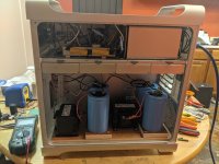
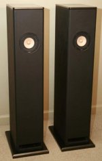
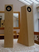
I have a pair of second hand Monitor Audio GR20 speakers, which are at least 15 years old I believe. These:


Monitor-Audio-GR20-450-B.jpg


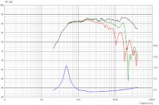
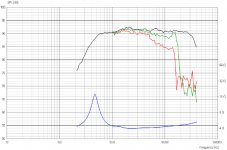
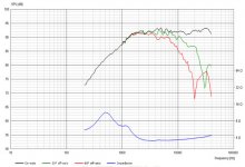
This is the measured (from here SoundStage! Measurements - Monitor Audio Gold Reference 10 Loudspeakers (10/2001)) listenting window frequency response of the GR10 which uses the same mid and tweeter (though obviously will have more bass weight and extension):


frequency_listeningwindow.gif


I've never been quite happy with the treble performance. Difficult to describe but overall it was qualitatively uneven (cymbals and guitars just didn't sound quite right). Oddly even though the graph above doesn't seem to show it the top end was just too loud overall (i ended up using the speaker grills which helped but led to other compromises), though of course that may be due to the room.


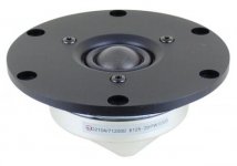
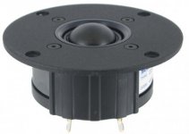
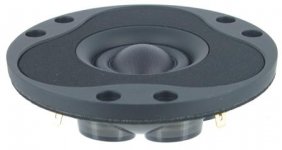
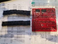
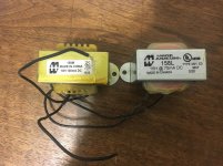
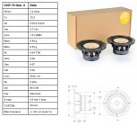
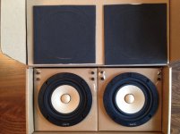
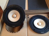
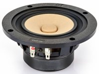
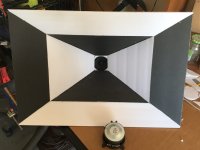
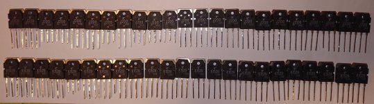
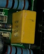
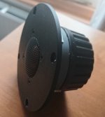
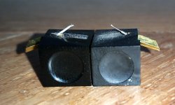
So having done a bit of reasearch and finding that MA use modified SEAS tweeters (attached is a picture of the old units) i decided to take a bit of a risk and get some replacement tweeters from SEAS. (having used SEAS units in the past I felt i at least knew they wouldn't be bad units). The units I chose are the 27TBFC/G. As i had no idea what the SPL of the existing units were I was expecting to have to pad them down as I thought it was unlikely that the exiting units had a higher sensitivity. But I decided just to swap them out first and see what i was left with. I was surprised that my first reaction was "they sound dull". As it happens it would seem like (purely from listening) that actualy the overal vocal range and mids are just much better balanced and the new tweeters are actually overall better integrated (again purely from listening) than the old ones.


Anyway to finally get to why I'm here (sorry for the long preamble). After a few days adjusting to the new balance I feel like the new tweeters could do with a tiny bit of a drop. The lower treble (going to guess the 3-5k region) feels just a touch too hot, (clearly i was expecting this region to be hotter as i expected the new tweeters to fill out the the suckout the old tweeters had, but it's gone just a touch too far). So i'd like to try padding down the tweeters by just 1db to see how they sound. I've measured the DC resistance of the old and new tweeters at 5.3 ohms, (about .5 ohm higher than SEAS state for the new tweeters, and presumably the old, but i'm going to put that down to my mulitmeters accuracy - it seems very sensitive to how the probes are positioned). According to MA the cross over is 2.7khz.

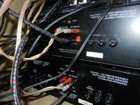
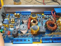
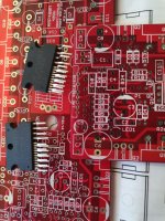
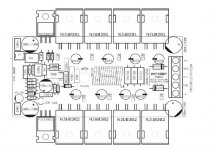
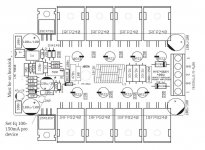
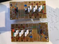
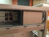
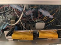
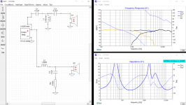
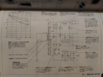
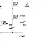
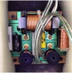
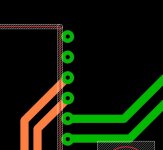
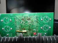
Attached is a picture of the exitsing crossover that i've managed to find. Going purely by a thread on this forum about the GS20 crossover, (here: Please help for Monitor Audio GS20 crossover tuning), I'm guessing the current one is a 2nd order HF (with a 3.3 Ohm resistor in series before the filter ciruit), first order mid (with notch filter) and first order bass.


So finally to my question 😱: As i don't want to mess around with cutting and soldering any of the existing wiring (and defintely not going to pull the speaker apart to start changing the original cross over) I was thinking of trying just a shunt resistor in parallel with the new tweeter to pad it down.


a) would this work?
b) what value resistor will i need to use to achieve a 1db drop? (according to the SEAS specs impedance runs 5 to 7 ohms between 2khz and 20khz on the new tweeters). I'd like to minimise any top octave drop in level/shelving of the response as much as possible. I'm thinking somewhere between 30 and 40 ohms?


Anyway goal is to drop the overall tweeter level by just 1db at this time, preferably using just a parrallel resistor, which I could solder on the existing wiring tags (thus avoiding having to put a soldering iron anywhere near the new tweeters).


I have no means to measure the speakers, and in all honesty I don't really want to get caught up in the effort all of that would entail. The speakers sound much better than they did previously, I'd just like to bring down the overall level of the tweeters a touch as i think they'd sound a bit better still if i did.

Attachments

  • GR20 Crossover.jpg
    GR20 Crossover.jpg
    277.9 KB · Views: 419
  • GR20 Tweeters.jpg
    GR20 Tweeters.jpg
    205.9 KB · Views: 279

Nagaoka MP11 Boron

Hi all. I have a question re. a possible design change to a vintage stylus I have and am hoping someone can shed some light on it.

With reference to the attached photograph:

I have a Nagaoka MP11 boron cartridge that I have had since about 1983 and a few weeks ago I decided I would like to start listening to it once again, but long story short, in the process of swapping headshells I dropped it and damaged the stylus.

Anyhow the desire to hear it play once again did not abate and I managed to track down a second-hand example and bought it. On comparing the styli I find that they are significantly different. My original one, on the left is a plain tubular design, flattened off at the tip, whereas the replacement example has a shaft mounted into a collar near the base and has no flattening of at the tip at all.

These seem to be very different designs and I find it strange to find that they are both designated the same model number - MP11 Boron. Surely such different approaches to presentation of the tip must result in significant differences in performance?

Can anyone explain what I am seeing here, or shed any light onto the history of this cartridge/stylus?

Thank you and regards.

Attachments

  • MP11s.jpg
    MP11s.jpg
    633.3 KB · Views: 621

LTC spice clean up

If you use LTC spice, you probably have a bunch of large temporary files that hang around using up disk space. I have found it very useful to place a file delete utility in the windows sendto folder. The Windows sendto folder has moved around with different windows versions but the current location is something like
%userprofile%\AppData\Roaming\Microsoft\Windows\SendTo

The file itself is a very simple bat file "spice cleaner.bat":

%~d1
cd %1
del /S *.raw *.log *.fft
pause

You just right click a folder, sendto -> "spice cleaner.bat". I prefer to pause the script before it closes so that I can see what has been found and deleted.

cheers,
Steve

DSP Decisions

I've been building my system for the past year or so. Here's my setup so far


Front: Focal ES165 K2 & Matching tweeters biamped
Rear: Hertz Hi Energy 165 component set
Subs: JL 12W3 shallow subs
Amps: JL 1000/1 (class D) and two Mosconi amps for the front/rear speakers
DSP: DBX Driverack PA2 modified to run on 12v
Sound deadoning 80% complete. Required removal of seats and carpet


The Focals take up four of the six channels of the driverack since they are biamped. This has a huge advantage since the tweeters a bit overpowering at high volumes. The DSP's limiter takes care of this. The other two channels are used as a limiter for the subs. This is essential as it's difficult or impossible to hear when they're reaching their limit.


With the recent addition of Hertz in the rear, I'll need a couple more channels of processing. Here are my thoughts so far:

  • Put a compressor on the subs to free up a couple of channels on the driverack
  • Use a SigmaStudio compatible DSP chip
  • MiniDSP C-DSP 8x12
  • Add another driverack
My biggest question is sound quality with all of these different options. Does anyone have experience with any of these products?

Sprint Layout 5.0 Double side pcb question

Hi everybody!

Merry Christmas 🙂

Till now i'm using Sprint Layout 5.0 for one sided pcbs fine.

I'm in the procedure of designing a double sided pcb for a DAC and i'm realy confused.

I put lets say a DIL28 (CS8412) in C2 side and now i need to add a track in C1 side connected to a pin of IC.

How i can add the pin pads in C1 side too? Only manualy?

Thank you very much.

I added 3 photos.

Attachments

  • 1.JPG
    1.JPG
    40.1 KB · Views: 114
  • 2.JPG
    2.JPG
    13.3 KB · Views: 110
  • 3.JPG
    3.JPG
    11.4 KB · Views: 101

Thermalright Heatsinks and fans

I'm listing these in hope that someone has a use for them for some kind of DIY project.

Enermax T.B. Silence 120mm Ultra Quiet Twister Bearing Cooling Fan (quantity 2)
link: https://www.amazon.com/Enermax-Silence-Twister-Bearing-UCTB12/dp/B003IB2HYA
price each: $9.99
CqB6Fwv.jpg


Thermalright Ultra 120 eXtreme CPU cooler
Link: Ultra-120 eXtreme Rev.C – Thermalright
price: $29.99
FhXGwmQ.jpg

IEIGLOy.jpg

eqQOyEI.jpg

Q68Dn1m.jpg


Thermalright IFX-14
link: IFX-14 – Thermalright
price: $29.99
OGojyvD.jpg

4zEWrQS.jpg

JNlwp2d.jpg


intel 115x and AMD AM4 mounting hardware for thermalright Ultra eXtreme 120 and IFX-14 (quantity 1)
https://www.amazon.com/Thermalright-100700553-Optional-Mounting-Installation/dp/B00UN05Q6A

as a bundle together $90 shipped and paypal'd

Selection guidance for LEDs

Hello Folks!

My LED application is supposed to signal OK with a green (3mm) LED and "not OK" with a red LED. The two LEDs are in different parts of the circuit and don't have common ground or supply.

I'm looking for a green and a red LED each providing the about same subjective brightness, but don't know which brightness (in mcd) to choose.

I'm also somehow missing a diagram in LED datasheets telling me the typical brightness vs. Diode current or/and voltage which would also be helpful in judging circuit sensitivity.

Any help enabling me to choose or proposal of specific LEDs for the purpose is thankfully appreciated!

Greetings,
Winfried

Quad 909 question

Hi I just wondered if anybody knows whether the 0.1uf cap (yellow) which connects from D14 to R16 (as per pic) is a valid quad modification or not. I would also be interested if anybody has any idea's on the purpose of this capacitor. I purchased the amp many years ago secondhand (unmodified at the time) however the capacitor was present at the time of purchase.
t

Attachments

  • quad 909 Cap mod 2.JPG
    quad 909 Cap mod 2.JPG
    125.6 KB · Views: 310
Projects by fanatics, for fanatics
Get answers and advice for everyone wanting to learn the art of audio.
Join the Community
507,758
Members
7,887,198
Messages

Filter

Forum Statistics

Threads
406,170
Messages
7,887,198
Members
507,758
Latest member
Cindy