Hi all.
I would like to share building 300B se amp from a book.
Posting might push my self...
Its my first experience and I had no knowledge/understanding tubes, cirkit etc.
Reading book, gathering items took me 6 month now.
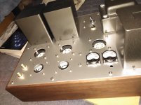
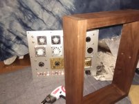
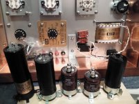
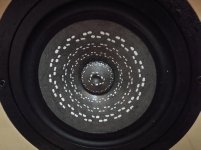
I put copper tape for shield(May be it works?)
I would like to share building 300B se amp from a book.
Posting might push my self...
Its my first experience and I had no knowledge/understanding tubes, cirkit etc.
Reading book, gathering items took me 6 month now.
I put copper tape for shield(May be it works?)
Attachments
-
 P_20181030_184416.jpg546.3 KB · Views: 1,249
 -
 P_20181030_183541.jpg438.1 KB · Views: 1,237
 -
 P_20181030_184044.jpg558 KB · Views: 1,246
 -
 P_20181106_202710 (1).jpg465.8 KB · Views: 1,174
 -
 P_20181106_202727 (1).jpg709.3 KB · Views: 1,132
 -
 P_20181106_195359 (1).jpg508.2 KB · Views: 508
 -
 P_20181106_201828 (1).jpg651.5 KB · Views: 538
 -
 P_20181106_202909.jpg527.2 KB · Views: 628
Yes the copper tape if grounded to the top plate will provide shielding. (I've used it with success in the few wooden chassis builds I've done.)
I would sleep better if a grid stopper resistor is in front of the UHF tube 6DL4. Nice Looking Amp BTW.
I'd put a grid stopper on the 300B as well.
It looks like a very nice build! The attention to detail paid here clearly shows. Nicely done!
Tom
It looks like a very nice build! The attention to detail paid here clearly shows. Nicely done!
Tom
Thanks for reply.
But I am not understanding what the grid stopper is...
From my book only say 75kΩresistor for grid leak (50k-100kΩ for fixed bias)
But I am not understanding what the grid stopper is...
From my book only say 75kΩresistor for grid leak (50k-100kΩ for fixed bias)
hacking the Western Electric 300B
Konichiwa tamra . The designer is far to be stupide to ignore about grid stoppers , you don't need to light any candle to "Saint Isidor" in order to harvest a better amplifier . The motto of the designer is to achieve the least possible cathode feedback of the 300B. But this circuit can function only with Western Electric expensive WE300. tube. I explain , generic 300bs have a single filament , if one side is 0 volt than the other is +5v ,this means the grid cathode voltage hence the plate current on one side in the tube is higher than the other . The plate becomes hotter on one edge than the other . With WE300b the filament is center tapped , by this the center of the cathode is lower potential than the sides ( this why the pin 4 must be grounded in one channel where the pin 1, Z, has +5v and inversely for the second channel which has at pin 4,X, -5v) ,by this the plate heats maximum at the centre . This is in DC , but in AC the story is still different . In the generic ones, the sides are grounded considering C19&20 are very high 100,000uf , then the center of the cathode sees each side with 2 ohms resistance , gives an internal feedback resistance of 1 ohms at the centre , resulting an average internal cathode resistance of 0.5 ohms . With WE 300B the story is different ,as it is centre tappet, at 1/3 &2/3 points on the fillament occurs maximum feedback, giving more uniform AC electron flux but with higher cathode resistance , and here is the hidden secret of the WE300b . With generic ones the bass is less pronounced than the WE for this reason . I don't understand what is the physics behind, but having the cathode resistance higher or lower the bass disapeares . WE didn't find this value by dreaming a monkey playing with coconuts ,precedent experiences , lead to this value. The 300a 10v/1.1 is has not been center tapped for 300b .
If you can't afford a WE300b , no you will not go to bed like an orphaned every night , there is an alternative. The 2.5volt version of 300b ,is center tapped . 2A3/40watt of 2A3C or Z (45$,110$ from Leisure-audio) can also be used with your amp by adjusting R14&15. As the cathode resistance is much lower you get hence less feedback hence , extra high frequency response To hack the WE for the bass, you need to adjust the impedance externaly with your ears by adding in series with C19&20 for maximum bass. This resistance once the value is known with film resistors, noninductive BRP56 must be used . This resistor can be shunted by another capacitor , so that the magnificent tweeter sound of 2A3is back . With my 2A3C replacing the 300b , 70hz sounded the best . That is ,WE300b sound below and 2A3C sound above.( As indicated in the schematic, point Y of each channel, must be star point to all grounds of that channel) Sayonara tamra.
Attachments
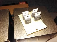
This isn't a criticism but the current meters may also be mounted from the underside of the top plate giving a lower visual profile. I believe that's the way they were intended to be mounted and you may or may not prefer the look. They will work equally well either way.
Arigatou gozaimasu Kokoriantz.
I dont have any plan to buy WE300B. But very interested in 2A3C.
I already bought PSVANE300B so I would like to listen 2A3 too.
From your explain,I understood difference of the filaments but need more study to understand grid stopper...
Thank you Hearinspace.
Yes you are right.
Recently I noticed that I might needed to have volatge meter instead of mA meter to check bias.
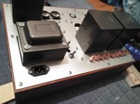
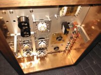
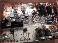
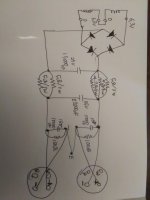
Started wiring little by little.
I shoped so many large caps .
Diode is sicsbd(Rohm SCS310AP)
I have bought sicsbd for Hypex UCD180 which I am using now.
I tried classic silicon diode with snabber cap,MSR1560,SCS106AG( Rohm 1st gen). Rohm SCS310AP (3rd generation) has It is a high surge current capability. Very low noise and clear sound, I really like this.
So I am thinking to parallel sicsbd+on/off switch with tube reflector.
Is it possible? Do I need some resistor on sicsbd?
Attachments
Arigatou gozaimasu Kokoriantz.
I dont have any plan to buy WE300B. But very interested in 2A3C.
I already bought PSVANE300B so I would like to listen 2A3 too.
From your explain,I understood difference of the filaments but need more study to understand grid stopper...
Since this is your first amp, I would leave it very much like in the book. Introduce grid-stopper and no other changes.
Note that the 2A3 need lower filament voltage and more current.
Also the B+ supply voltage is towards the upper limit for 2A3. For these reasons, to replace 300b with 2A3 you may need different mains transformer.
Build with what you have.
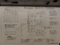
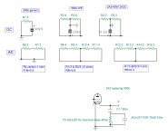
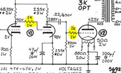
For grid-stop resistors you may want to check out: The Valve Wizard
Also see highlighted resistors in attached schematic. Remember to keep resistor close to the gris pin.
Attachments
The filament supply is made of 2x6.3v in series for 300b. If 2A3C or 2A3/40w is used ,they can be wired in parallel.
Grid stoppers create internal feedback in the tube and decreases considerably the presence of the voice . The designer , certainly of great knowledge , purposely omitting using any . Listen first the sound as designed than degrade it by resistors .
Thank you LGT and kokoriantz.
I like to listen opinions even criticism.
I also like try many things.
Recently while I am studying for grid leak,in Japan many people likes to use grid choke coil
intead of resistor. Choke coil has low DCR and high impedance for first stage tube.
But from my knowridge, I can only build as same as book now.
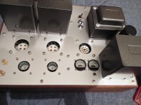
Its getting something like nest.
I am installing volume pod. But dose 8w tube amp really need volume pod?
I usually adjust volume with DAC and PC so.
I have bought alpair 10PeN. I will build trapezoid mar-ken soon.
Thanks Dave & people here. I am having good time building
my own music system.
I am installing volume pod. But dose 8w tube amp really need volume pod?
I usually adjust volume with DAC and PC so.
I have bought alpair 10PeN. I will build trapezoid mar-ken soon.
Thanks Dave & people here. I am having good time building
my own music system.
Attachments
I am installing volume pod. But dose 8w tube amp really need volume pod?
I usually adjust volume with DAC and PC so.
In a typical PC, volume controls is achieved by digitally dividing the signal value. Lower volume music will be represented by a set of small number, meaning at small volume it won't have as much resolution. That compounded with a non-ideal DAC and a noisy environment, audio quality will suffer at small volume. I would put in an analog volume control.
kokorinatz,
And tamra,
Two parallel 6.3V 2A filaments = 6.3V 4A.
One single 2A3, or 2A3-40, or 2A3(x) filament needs 2.5A
For AC power filaments you need 2.5A per 2A3, or 5A for two 2A3s.
The paralleled 6.3V windings (4A total) will only power one 2A3 with AC.
If you rectify AC and use a Capacitor input filter, you need 1.6 times the AC current rating
of the filament winding, versus the DC load Amps.
2.5A X 1.6 = 4.0 Amps per 2A3 = 8A for two 2A3 tubes.
A 4A transformer can not give DC power for two 2A3 tubes.
When I get some time, I will calculate and post a schematic that will properly
power your two 300B tube filaments with DC, and will also take care of the proper
balance for 300B tube filament voltages at the two filament ends.
(by using the two 6.3V 2A filament windings you already have).
If you ever have to parallel two 6.3V windings, just make sure of 2 things:
Be sure the phase is the same before connecting them, or you will burn them out.
Be sure they are rated for the same Amps, or one will heat more since it takes more than 1/2 of the load.
Last edited:
tamra,
As was pointed out in an earlier post, the 300B tubes have an imbalance of the bias circuit versus the DC filaments of 5V. That results in more plate current flowing from the negative (-) 300B filament than from the positive (+) 300B filament.
If the power transformer’s two 6.3V 2A filament windings are tied together like a center tap (do not have 4 separate connections), then you will have to build the 300B filament circuits as in the schematic.
But if the two 6.3V 2A filament windings are not connected together and have 4 separate connections, then you can change the circuit if you wish. It would take one Schottky Bridges with the current capability, two additional 10 Ohm resistors, and the rest of the components the same. If your transformer does have the 4 separate connections (separate 6.3v 2A secondaries), and if you are interested, I will post a schematic of the modification. Let me know.
- Home
- Amplifiers
- Tubes / Valves
- 300B SE as my first tube amp