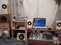
Awesome, you're off to a good start. The copper tape is good shielding.
That new ISO iron looks very tempting!
That new ISO iron looks very tempting!
Thanks deafbykhors. I had no experience with tube amps and I didnt know even 300B or something like OPT mechnichs. From my small research,I chose from 3 of those inexpensive OPTs. ISO, Softon Rcore OPT Softone RW-20 Single-Ended Audio Output Transformer Toei-transformers ???????????????? Some Review says ISO has punchy sound with low frequency. Softon is clean sound,Toei is famous for low-priced and good sound Toei products are mostly hilite core (one oriented hi-b core).Its cheap and always good review from professional engineers.It is said that price comes from company owners honesty since 1958 in Akihabara. Finemet core transformers has best reviews but costly.
Recently I started DIYAUDIO then I also getting enjoying busy Tokyo. Akihabara is always busy with foreigners and also Japanese.Funny that now I like taking walk in Akihabara instead of trekking forests and mountains. For travelers, accommodations are getting cheaply in Japan and visitors are getting more and more now.If any chance, please visit Japan.There are so many nice food,hot springs and audio parts.
Recently I started DIYAUDIO then I also getting enjoying busy Tokyo. Akihabara is always busy with foreigners and also Japanese.Funny that now I like taking walk in Akihabara instead of trekking forests and mountains. For travelers, accommodations are getting cheaply in Japan and visitors are getting more and more now.If any chance, please visit Japan.There are so many nice food,hot springs and audio parts.
tamra,
I am attaching a schematic for separate 300B filament supplies.
The ripple of the supply is low enough that you will have less than 200uV rms (200 microvolt rms) hum at the output transformer secondary to the loudspeaker (that is caused by the small filament supply ripple). You will have to work hard to get all the other contributors to hum that low.
I included a 10 Ohm sense resistor, so you can properly set the grid bias to get the plate current you want (I did not see what the schematic called for plate current, 50mA, 60mA, or how much?).
You do have to adjust the dropping resistor that is in parallel with the 3 Ohm resistor. The warm up of the 300B filament is long until the voltage stabilizes. You want to adjust the 10 Ohm parallel resistor until it and the 3 Ohm give you 5V across the filament after a 2 minute warm-up.
You may choose to change the 1k Ohm bleeder to 100 Ohms. If you are testing the power supply, and do not have a 300B installed, the filament voltage will rise to about 8V or more. Then, after you power the amp down and plug a 300B in, the 5V filament will get a 8V transient, if the bleeder did not yet bleed the voltage down.
Also, there are no bleeders on the B+ supply. A pair of 25k Ohm 5 Watt resistors in series, will help to reduce the B+ voltage after you turn the amp off, and then open the cover plate to work on the amp. Safety first.
I hope for many happy listening hours for you.
Attachments

Last edited:
300B plate current is 70mA 350V. I checked 300B filament voltage from previous schematic. One is 4.65V and other one is 5.3V. It looks much better to change separate. Separate filament supply you show me,looks I need 10Ω for connect earth and - of filament pin right?
The 10 Ohm resistor that connects from ground to the Negative 5V filament supply is for two reasons: 1. It passes current from ground (which is also the B+ ground) so that electrons pass from the filament past the grid, and on to the plate. It increases the plate resistance by less than (<) 40 Ohms (700 Ohms + <40 Ohms); not a problem. Do not forget, the Negative terminal of the B+ supply is connected to ground. 2. It is so you can easily measure the current from the filament to the plate. 70mA through 10 Ohms will give 0.7V (700mV) from ground to the Negative 5V. Set the 300B grid bias pot until you get 0.7V across that 10 Ohm resistor (with the 300B tube warmed up).
The Other 10 Ohm resistor, the one across the 3 Ohm resistor . . . it might need to be 8 Ohms, it might need to be 12 Ohms, 10 Ohms, etc. It is adjusted so there is 5V DC across pin 4 and pin 1 of the 300B (when the filament is warmed up, it takes a little time). The variables are your power line voltage, your power transformer, your Schottky Diode Bridge voltage drop. Shoot for 5V DC, when your power line is at its average voltage.
For example, my power varies from 117V on a cold winter day with me and the neighbors using electric heat, electric water heat, electric stove; Then on some days and nights my power is at 123V. I wait for a day of 120V, and set the value of that "10" Ohm resistor until the filament voltage is 5V from pin 4 to pin 1.
The heat that is dissipated in your 300B is: A. 5V x 1.25A = 6.25 Watts And, B. 350V x 0.75A = 24.5 Watts That is a total of 6.25 W + 24.5W = 30.75 Watts. This is a Class A output stage. That power is constant for no music and also essentially for music that is not near clipping. The principle is: all that power is in the 300B with no music, and then some of that power is sent off to the loudspeaker when music is present. Surprising, isn't it.
Last edited:
Thank you for detailed instruction. It is really helpfull. Do you also add resistor with first stage tube filament wire?
tamra,
Good question.
In my opinion, I would prefer not to connect the V1 and V3 filament winding directly to ground, as is shown in Post #1. Instead, just use a couple of 50 Ohm resistors, one from one end of 6.3V to ground, and the other 50 Ohm resistor from the other end of the 6.3V to ground.
That balances the voltage just the same as if you were using a 6.3V Center Tapped winding with the Center Tap connected to ground.
That means that each end of the 6.3V is 3.15V away from ground, instead of one end at 0V from ground and the other end at 6.3V from ground.
Thank you so much, I will do. Today,I finished wiring and start checking voltage. Filament is ok. Set bias -75V. Then I put every tubes and on the switch. Few seconds later V1 plate voltage going up more than 300V so I off the switch... I mistake something so checking again.
300V+ seems normal to me. At -75V bias, you should have a plate current around 60mA. If your output transformer DCR is around 100R, the voltage drop on the output transformer is only about 6V. You should have around 340V at the plate at idle. Monitor your plate current is more important at initial power up. Make sure no over plate current stress that can damage to the expensive OPT and 300B. You can do that via the 10 ohms mentioned in earlier post.
The 5V3 rectifier warms up quickly, a 5AR4 warms up slowly, and the 300B warms up slowly (because of the resistors from one cap to the other cap in the 5V 300B filament supply). Therefore, the B+ voltage goes a little higher at the start, versus later when all the tubes are warmed up. The 6DL4 takes time to warm up. So it does not draw current through the 24k plate load resistor until it is warmed up. That means the full B+ will be on the 6DL4 plate at first. It should go down when all is warmed up.
After the amp is turned off, and unplugged, wait until all the caps are discharged, check with a meter set to 500V or more. You should have bleeder resistors across the B+, or it may not go down for a Very Very long time. Next make some Ohmmeter checks: The 6DL4 plate (pin 8) should have 24k Ohms to the 10k B+ resistor.
The 6DL4 cathode (pin 2) should be 330 Ohms to ground.
The 6DL4 grid (pin 1, 3, 6, 7, 9) should be 50k to ground with the volume control turned up.
The 6DL4 grid (pin 1, 3, 6, 7, 9) should be 0 Ohms to ground with the volume control turned down.
The 6DL4 filament is pins 4 and 5, they should connect to different ends of the 6.3V filament winding.
If the 6DL4 is bad, like an open filament, the plate will always be at B+ voltage.
Last edited:
Thank you so much. Allensoncanon, sorry for my explanation. Plate at 300B is around 350V but ec88 had some voltage too. I have checked wiring many times but nothing wrong. I have no experience at all for tubes so I am afraid but I will wait to warm up. Thank you 6U3sUMMER I will check with multi meter what you suggest.
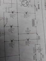
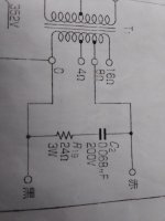
This book says he add 220kΩ to C13 for B+ bleeder so I will add. He also add 0.068uf and 24Ω on OPT to fix oscillation at 10kHz. I am not sure it works because this book use Tango FW-20s, mine is similer OPT from new ISO FC-20s. I have add type 50kΩ volume pod so it might be ok. TOKYO KO-ON DENPA WEBSITE Tokyo ko-on and Tokyo cosmos sells good quality volume pods,I saw many good reviews.
This book says he add 220kΩ to C13 for B+ bleeder so I will add. He also add 0.068uf and 24Ω on OPT to fix oscillation at 10kHz. I am not sure it works because this book use Tango FW-20s, mine is similer OPT from new ISO FC-20s. I have add type 50kΩ volume pod so it might be ok. TOKYO KO-ON DENPA WEBSITE Tokyo ko-on and Tokyo cosmos sells good quality volume pods,I saw many good reviews.
I am sorry for my english is not enough to understand accurately. I have wired like picture below.The 6DL4 filament is pins 4 and 5, they should connect to different ends of the 6.3V filament winding.
Attachments


Tamra,
You are using a ECC88 instead of 6DL4. Put a 1 k Ohm resistor on grid (Pin 2) right at the tube socket tab; other end to the signal wire. Put a 1 k Ohm resistor on grid (pin 7) right at the tube socket tab; other end to the signal wire. These are called Grid Stopper resistors. They are in series, between the signal that goes to the grid and the grid (the other end of the 1k Ohm goes to the grid).
You may have to reduce the 330 Ohm 6DJ8 Cathode Resistors a little to get the 6DJ8 plate voltage a little lower, if it is too high when the tubes are warmed up. If the voltage is too high, 220 Ohms might be a good value to try.
You are not using Negative Feedback, are you? The combination of negative feedback, input tube, circuit values, wiring placement, and output transformer can cause oscillation.
You did not use any resistors to connect from the 6.3V input tube filament transformer secondary terminals to ground. Two resistors (equal resistance) of any value from 25 Ohms each to 100 Ohms each will keep the filaments from floating.
Last edited:
Its EC88/6DL4 tube. Not ECC88/6DL8.
An externally hosted image should be here but it was not working when we last tested it.
For the EC88, it still is a good idea to use a grid stopper for each triode. Those are UHF RF tubes.
And do not forget to use resistors from the input tube 6.3V secondary connections to ground.
Is there any negative feedback?
I did not see any in the schematic post #1.
And do not forget to use resistors from the input tube 6.3V secondary connections to ground.
Is there any negative feedback?
I did not see any in the schematic post #1.
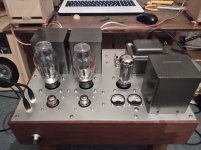
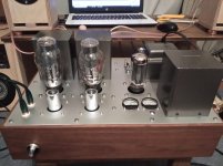
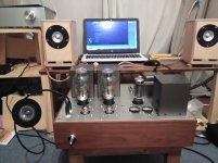
Yes!! surprisingly good sound!Its tight sound which I did not much expected! Thank you all for suggestings. I took out ES88 heater GRN but I will connect with 10Ω sooner. There is no feed back here but I can try later. Tubes are pretty hot. I am little scared but seems ok.
Attachments
I would like to try gridstopper. I did not find any info from Japanses books or web.Only for guitar amps. Dose grid stopper connect between grid pin of 300B and C3,8 coupling caps? And how much Ω?For the EC88, it still is a good idea to use a grid stopper for each triode. Those are UHF RF tubes.
And do not forget to use resistors from the input tube 6.3V secondary connections to ground.
Is there any negative feedback?
I did not see any in the schematic post #1.
The shield of 6dl4 tube (aluminium cover) makes sound bad like spongy so took out. I also try to use 5AR4 instead of 5U4GB. I think I can use adjusting bias voltage. Adding bleeder resistor makes less plate voltage so It might works.
I am so excited that this amp sounds great. Thank you everyone and diyaudio forum!
tamra,
Look at post #1, C3 and R4 are connected together, then to the 300B grid.
Instead of connecting the junction of C3 and R4 directly to the 300B grid, connect
a 1k Ohm grid stopper resistor in series from the junction of C3 and R4 and the 300B grid. See the grid stopper resistor on the output tube in Post # 11.
Do the same thing for C8 and R9 junction, and use another 1k Ohm resistor connected to the other 300B grid.
You also need 1k Ohm resistors on the 6DL4 grids. See the wire that is shielded that comes from the wiper of the 50k Ohm pot. Take that shielded wire off the 6DL4 grid, and connect it to a 1k Ohm resistor. Then connect the other end of the 1k Ohm to the grid.
If you are using EC88 tubes, do use 1k Ohm grid stoppers there too.
After that, see if the tube shields still make the sound not to your liking (probably do not need to use the shields anyway, this is a two stage triode amp).
A 1k Ohm grid stopper will not ruin the high frequency signal, because it is only 1k Ohms, but it should prevent any tendency of the tube to oscillate.
I only asked if you were using negative feedback (I was not recommending it). It does not appear in the schematic of post #1.
Do not use negative feedback for this amplifier. It is all triode, and has 300B output tubes that give fairly low distortion and fairly good damping factor. Negative feedback is not necessary.
But if you do use negative feedback for this amp, it could cause instability or perhaps oscillation, and will also lower the gain. Fixing all that might be more trouble than it is worth.
Last edited:
Agree with 6A3sUMMER. If you get any oscillation (such as motorboating) , then addition of a modest gridstopper resistor will likely solve it.
If you do not have any oscillation, then maybe you don't need a gridstopper. My experience with 300b and 2a3 suggests a gridstopper is a good thing and has zero bad effect on sound, frequency response, etc. I put it right at the grid socket pin (as previously noted).
Also, there is generally no need for shielding with copper tape. But twisting any and all AC wires (including signal conduction wires, and prevent any ground loops (should eliminate any hum). Shields on the EC88 valves/tubes should really have zero effect, but they should also not be necessary.
Very nice build!
Ian
Thank you,I will buy some 1kΩs. I am having fun with modifying and checking. I dont really feel it noisy at this time. I have tried 0.068uf and 24Ω at secondary of OPT. Sound more cleaner but made sound boring so I took it up. Then I have wired 200kΩ as bleeder. It changed less bass sound slightly. I have prepared extra switch for softstart or silicon diode (previous plan but now I feel I dont need silicon diode) so I use for bleeder switch on and off. I am surprising that 300B single amp has good bass sound.
A 300B that has about 300 volts or so across it, and 75mA quiescent current will have a plate resistance, rp, of between 600 and 700 Ohms. That rp will provide both a fair damping factor, and will work with the primary inductive reactance at low (bass) frequencies . . . if you use a good single ended output transformer with correct primary impedance, reasonable primary inductance, enough laminations, and low DCR windings.
Your amp should work very well.
Your amp should work very well.
- Home
- Amplifiers
- Tubes / Valves
- 300B SE as my first tube amp