Dual 18SW115 BP6S with a "mid chamber", model approximation advice?
- By recon440
- Subwoofers
- 17 Replies
Hello everyone,
I'm looking for advice on most accurately modelling a 6th order enclosure. Currently I have a 6th order using two Alpine Type-R 12's but for the next season I've decided to go bigger and have chosen to employ two 18's and fitting them has introduced some unique geometrical constraints that I am not sure how to best approximate in Hornresp.
At a high level the object will be to play broadband 35Hz-100Hz at power levels ~1000W-3000W. I've decided to go with PA drivers this time because B&C 18SW115s came up at a steal of a price (~400CAD each, new). Additionally, they seem to best the the Type-Rs in all other categories; weight, power handling/compression, mid-band sensitivity, still have generous excursion capability.
As I've modelled and built 6th's well in the past I was hoping to model conventionally with the rear section firing forward (thus eliminating a mid chamber). Unfortunately after building the rear section it appears that am short 1" in terms of clearance to close the trunk, thus I have to lay the rear section flat and have the drivers firing downward which introduces some interesting considerations of having a mid-chamber (I guess turning this enclosure into technically an 8th order).
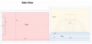
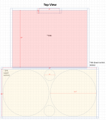
In nutshell, this system comprises of three sections in order to fit inside the trunk (will be sealed together using foam gaskets so they can be easily disassembled). The images I put together PPT below show the general configuration. The side-view I think most clearly shows the geometry of what I am dealing with.


(All values below are net after displacements, wood thickness is 0.75" MDF)
- Rear (yellow): ~104L: houses two B&C 18SW115s, two 22cm 4"ID PVCs, when considered standalone tunes to ~38Hz. The drivers are recessed in this chamber by 0.75" for speaker protection.
- Mid (blue): ~42L: a chamber with an open-top that serves a "pedestal" for which the rear chamber to fire into. In essence, the foot-print of this chamber is identical of the rear chamber that is mounted atop of it. The front of this chamber has an opening to where it mates to the front chamber; the opening here will be ~3"x29.5". This chamber is the crux of the problem as it has an effective axial area of ~895cm^2 (3.75"x37") over a length of 47cm which then steps into to front chamber having an aperture of 571cm^2 (3"*29.5").
- Front (red): ~136L: this chamber sleeves the inside portion of the trunk and mates up to the ski pass (~489cm^2 of port, ~2" in length but this can be adjusted as needed). From the top, the front chamber is slightly narrower than the rear/mid chambers.
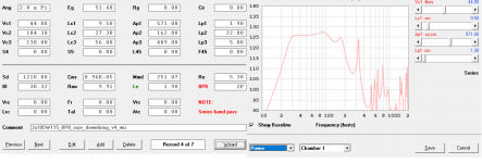
Modeling is done in Hornresp, with 1kW of power, using semi-inductance parameters I've derived from the impedance curve. The volume of each section is quite trivial (~286L total in each model) but it seems that the geometry (in terms of length/areas) results in significant deviations from model to model. I would appreciate any advice on what would be most appropriate. The problem at hand is that I don't think I can bin the mid and front chambers and consider them simply in terms of volume as I think there are some compression effects happening in the mid-chamber.
Model 1: TH1 using a standard rear chamber, mid-chamber is approximated ~895cm^2 using two horn sections (this not account for the step change into a 29.5"*3" (571cm^2) aperture into the front chamber.

Model 2.1: TH1 using a standard rear chamber, mid-chamber is accounted for in Vtc/Atc; Atc is 4416cm^2 giving a length of 9.52cm, this loads into the front chamber through the 29.5"*3" aperture into the front chamber which is accounted for here

Model 2.2: TH1 using a standard rear chamber, mid-chamber is accounted for in Vtc/Atc; Atc is 895cm^2 giving a length of 47cm, this loads into the front chamber through the 29.5"*3" aperture into the front chamber which is accounted for here

There are a couple critical questions in regards to the models:
- Models 2.1 and 2.2 are quite similar with the difference being the consideration of the "length" of the chamber relative to everything else. Is it seen as 9.52cm (height) or 47cm long (length). I like these in that they both consider loading into the front chamber through the step change in the mid chamber but are quite different due to the considered length of the mid-chamber? What is most appropriate? Or maybe something in the middle, like a 24cm approximation of length.
- What is the most "correct" placement of the front and rear entry points? Effectively, I would like to have woofers and port as a single point loading in at 25cm (the center point of mid-chamber) but I don't think that it's possible to do with more segments, which I don't believe Hornresp supports. Given horn-resps constrains it seems that the driver and vents are offset by some distance which results in model differences between the two.
Model 3: BP8 Wizard where the mid-chamber step is considered as a 0.75" port of area 571cm^2. I think this one is the most ambiguous of what is happening in terms of geometry.

All in all, I think the responses in all models looks fairly workable in the frequency band I want to target but it would be nice to have a relatively flat response with slight emphasis at 40Hz (which model 2.1 presents).
As always, I would be very greatful for any advice and insights on this design.
I'm looking for advice on most accurately modelling a 6th order enclosure. Currently I have a 6th order using two Alpine Type-R 12's but for the next season I've decided to go bigger and have chosen to employ two 18's and fitting them has introduced some unique geometrical constraints that I am not sure how to best approximate in Hornresp.
At a high level the object will be to play broadband 35Hz-100Hz at power levels ~1000W-3000W. I've decided to go with PA drivers this time because B&C 18SW115s came up at a steal of a price (~400CAD each, new). Additionally, they seem to best the the Type-Rs in all other categories; weight, power handling/compression, mid-band sensitivity, still have generous excursion capability.
As I've modelled and built 6th's well in the past I was hoping to model conventionally with the rear section firing forward (thus eliminating a mid chamber). Unfortunately after building the rear section it appears that am short 1" in terms of clearance to close the trunk, thus I have to lay the rear section flat and have the drivers firing downward which introduces some interesting considerations of having a mid-chamber (I guess turning this enclosure into technically an 8th order).
In nutshell, this system comprises of three sections in order to fit inside the trunk (will be sealed together using foam gaskets so they can be easily disassembled). The images I put together PPT below show the general configuration. The side-view I think most clearly shows the geometry of what I am dealing with.
(All values below are net after displacements, wood thickness is 0.75" MDF)
- Rear (yellow): ~104L: houses two B&C 18SW115s, two 22cm 4"ID PVCs, when considered standalone tunes to ~38Hz. The drivers are recessed in this chamber by 0.75" for speaker protection.
- Mid (blue): ~42L: a chamber with an open-top that serves a "pedestal" for which the rear chamber to fire into. In essence, the foot-print of this chamber is identical of the rear chamber that is mounted atop of it. The front of this chamber has an opening to where it mates to the front chamber; the opening here will be ~3"x29.5". This chamber is the crux of the problem as it has an effective axial area of ~895cm^2 (3.75"x37") over a length of 47cm which then steps into to front chamber having an aperture of 571cm^2 (3"*29.5").
- Front (red): ~136L: this chamber sleeves the inside portion of the trunk and mates up to the ski pass (~489cm^2 of port, ~2" in length but this can be adjusted as needed). From the top, the front chamber is slightly narrower than the rear/mid chambers.
Modeling is done in Hornresp, with 1kW of power, using semi-inductance parameters I've derived from the impedance curve. The volume of each section is quite trivial (~286L total in each model) but it seems that the geometry (in terms of length/areas) results in significant deviations from model to model. I would appreciate any advice on what would be most appropriate. The problem at hand is that I don't think I can bin the mid and front chambers and consider them simply in terms of volume as I think there are some compression effects happening in the mid-chamber.
Model 1: TH1 using a standard rear chamber, mid-chamber is approximated ~895cm^2 using two horn sections (this not account for the step change into a 29.5"*3" (571cm^2) aperture into the front chamber.
Model 2.1: TH1 using a standard rear chamber, mid-chamber is accounted for in Vtc/Atc; Atc is 4416cm^2 giving a length of 9.52cm, this loads into the front chamber through the 29.5"*3" aperture into the front chamber which is accounted for here
Model 2.2: TH1 using a standard rear chamber, mid-chamber is accounted for in Vtc/Atc; Atc is 895cm^2 giving a length of 47cm, this loads into the front chamber through the 29.5"*3" aperture into the front chamber which is accounted for here
There are a couple critical questions in regards to the models:
- Models 2.1 and 2.2 are quite similar with the difference being the consideration of the "length" of the chamber relative to everything else. Is it seen as 9.52cm (height) or 47cm long (length). I like these in that they both consider loading into the front chamber through the step change in the mid chamber but are quite different due to the considered length of the mid-chamber? What is most appropriate? Or maybe something in the middle, like a 24cm approximation of length.
- What is the most "correct" placement of the front and rear entry points? Effectively, I would like to have woofers and port as a single point loading in at 25cm (the center point of mid-chamber) but I don't think that it's possible to do with more segments, which I don't believe Hornresp supports. Given horn-resps constrains it seems that the driver and vents are offset by some distance which results in model differences between the two.
Model 3: BP8 Wizard where the mid-chamber step is considered as a 0.75" port of area 571cm^2. I think this one is the most ambiguous of what is happening in terms of geometry.
All in all, I think the responses in all models looks fairly workable in the frequency band I want to target but it would be nice to have a relatively flat response with slight emphasis at 40Hz (which model 2.1 presents).
As always, I would be very greatful for any advice and insights on this design.









![PXL_20201230_142439694[1].jpg](/community/data/attachments/812/812329-e7bd9378e855a4eace7777f555547165.jpg?hash=572TeOhVpO)
![PXL_20201230_142448625[1].jpg](/community/data/attachments/812/812343-68816c04b48f932e9c5a5e582657cf73.jpg?hash=aIFsBLSPky)


