Hello,
So this was (still is) my first speaker project.
I'm using 2 woofers connected in parallel both in a seperate vented box.
It uses a 3th order crossover.
At the moment everything is still as-designed, but now it's time for some fine-tuning. They sound ok, but there's a lot of room for improvement.
Now, I'm thinking of doing the following:
- Splitting up the Zobel network
So far there's 1 zobel network per cabinet, calculated for the woofers being parallel. I'll split this up so that each woofer has it's seperate Zobel.
- Baffle Step Correction
The frequency response is suffering from some baffle step (I guess so).
Will probably start with a baffle step correction for 3 or 4 dB attenuation, I'll see from there...
I'm still not sure if I can simply calculate the baffle step correction with just the Re devided by 2 and the width of the baffle by the actual width of it.
Since it's a bit more complicated because the 2 woofers are connected parrallel.
Please share your thoughts with me 😀


Regards and happy holidays
So this was (still is) my first speaker project.
I'm using 2 woofers connected in parallel both in a seperate vented box.
It uses a 3th order crossover.
At the moment everything is still as-designed, but now it's time for some fine-tuning. They sound ok, but there's a lot of room for improvement.
Now, I'm thinking of doing the following:
- Splitting up the Zobel network
So far there's 1 zobel network per cabinet, calculated for the woofers being parallel. I'll split this up so that each woofer has it's seperate Zobel.
- Baffle Step Correction
The frequency response is suffering from some baffle step (I guess so).
Will probably start with a baffle step correction for 3 or 4 dB attenuation, I'll see from there...
I'm still not sure if I can simply calculate the baffle step correction with just the Re devided by 2 and the width of the baffle by the actual width of it.
Since it's a bit more complicated because the 2 woofers are connected parrallel.
Please share your thoughts with me 😀
Regards and happy holidays
Last edited:

I don't really see a question in your post, if you are aiming for an help it would be nice if you share something about the speakers (drivers, crossover).
IME a Zobel is mainly unnecessary, it's main purpose is to flatten the impedance in order to easily calculate a crossover. However with crossover simulators there is no need to have a flat impedance to design a crossover. I'd simply avoid the Zobel at all.
I don't understand the choice of two separated tuned boxes for the two woofers. In a MTM 2 way you should treat the two woofers in parallel as a single driver that are driven by the same signal, so a single tuned box is appropriate.
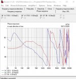
I see that the summed response between 3.5-5.5KHz is lower than the response of the tweeter alone. This means that the drivers are out of phase relatively near the crossover point. I would concentrate some effort in resolve the issue.
My last suggestion is to use gated measurements. Only this way you can clearly see what really happens and take the appropriate measures.
Ralf
IME a Zobel is mainly unnecessary, it's main purpose is to flatten the impedance in order to easily calculate a crossover. However with crossover simulators there is no need to have a flat impedance to design a crossover. I'd simply avoid the Zobel at all.
I don't understand the choice of two separated tuned boxes for the two woofers. In a MTM 2 way you should treat the two woofers in parallel as a single driver that are driven by the same signal, so a single tuned box is appropriate.
I see that the summed response between 3.5-5.5KHz is lower than the response of the tweeter alone. This means that the drivers are out of phase relatively near the crossover point. I would concentrate some effort in resolve the issue.
My last suggestion is to use gated measurements. Only this way you can clearly see what really happens and take the appropriate measures.
Ralf
Ralf is right. You haven't given us enough to go on.
Looks like the Peerless 830883 on midwoofer duties:
Peerless 830883 HDS 180 NOM Exclusive Woofer Speaker
Can't make out the tweeter.
Some awkward peakiness at about 5kHz there. Usually you notch that either with an LCR shunt or a tank notch which is an RC across the bass coil. This Troels 2.5 design uses a 6kHz tank notch on the mid:
PEERLESS-NOMEX-164
Have you modelled it in some way? Software | Visaton
Use the W 170 S - 8 Ohm | Visaton and the G 20 SC - 8 Ohm | Visaton.
Should be close enough to see what works.
Steve, today is your name day. I wish you all the best and a long and productive DIY life here and in general. Cheers!
Well, thank you very much. I'd forgotten that!
I really don't do as much as I used to. Everything works well enough here.
We have got the hang of this business.
😀
I really don't do as much as I used to. Everything works well enough here.
We have got the hang of this business.
😀
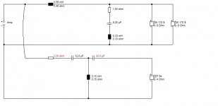
I dug up a bit of notching on a 6" bass:
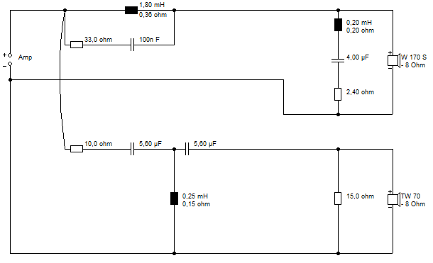
The bass LCR at 6kHz is the main event. The 33R/100nF tank does little and could be skipped. That's good rolloff IMO.
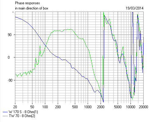
Excellent lined-up phase, but 90 degree phase works too with an MTM. 90 degree phase has a nice flat power output.
For a 4 ohm MTM you halve coils and resistors and double capacitors in the bass circuit and run the tweeter 6 dB louder..
The bass LCR at 6kHz is the main event. The 33R/100nF tank does little and could be skipped. That's good rolloff IMO.
Excellent lined-up phase, but 90 degree phase works too with an MTM. 90 degree phase has a nice flat power output.
For a 4 ohm MTM you halve coils and resistors and double capacitors in the bass circuit and run the tweeter 6 dB louder..
Last edited:
Steve,
I'm always amazed by the fact that you take the time to simulate in details a crossover but without using valid data. AFAIK in boxsim you can also use custom frd and zma files, choosing to simulate a crossover using Visaton drivers data instead of the measured data of the correct drivers makes the output useless (here simulating a Peerless 830883 using Visaton W170s data). I concur that your crossover can sometimes show a trend, but inexperienced people can think that what you show can be implemented in this exact way with the outcome you are showing.
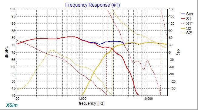
As I happen to have real measurement of the Peerless 830883 (and a Seas 27TBFC/G tweeter) for both FR and impedance, I simulated what happens with your crossover, and the result is not so nice. Also phase of the two drivers at crossover point doesn't match.
Ralf

I'm always amazed by the fact that you take the time to simulate in details a crossover but without using valid data. AFAIK in boxsim you can also use custom frd and zma files, choosing to simulate a crossover using Visaton drivers data instead of the measured data of the correct drivers makes the output useless (here simulating a Peerless 830883 using Visaton W170s data). I concur that your crossover can sometimes show a trend, but inexperienced people can think that what you show can be implemented in this exact way with the outcome you are showing.
As I happen to have real measurement of the Peerless 830883 (and a Seas 27TBFC/G tweeter) for both FR and impedance, I simulated what happens with your crossover, and the result is not so nice. Also phase of the two drivers at crossover point doesn't match.
Ralf
Attachments

Doesn't look too bad to me Ralf as a first stab! 😀
The tweeter filter I used here would be entirely wrong for a dome tweeter:
Cone tweeters are very different animals from domes. A dome would work better with your regular 1:3 capacitor ratio BW3.
But really I was just trying to convey how notches work, and the 830883 probably needs one. Since you have the modelling, perhaps you can knock this one into shape, er, with a bit of tweeter guess work! 😎
I know what your main purpose is, what I'm saying is that some people will not understand the purpose and think that the crossover shown will yield exactly the output shown, also with different drivers. My earlier implementation of the 830883/27TBFCG combo can be seen here, including measurements: Another 6.5”+1” BR design (Peerless HDS + Seas Prestige)
BTW, this reminds me that I'm currently using a slightly modified crossover with a lower crossover point, it is time to revisit that thread.
Ralf
BTW, this reminds me that I'm currently using a slightly modified crossover with a lower crossover point, it is time to revisit that thread.
Ralf
I dug up a bit of notching on a 6" bass:
The bass LCR at 6kHz is the main event. The 33R/100nF tank does little and could be skipped. That's good rolloff IMO.
Excellent lined-up phase, but 90 degree phase works too with an MTM. 90 degree phase has a nice flat power output.
For a 4 ohm MTM you halve coils and resistors and double capacitors in the bass circuit and run the tweeter 6 dB louder..
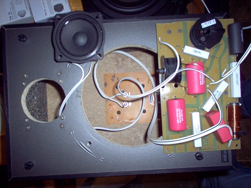
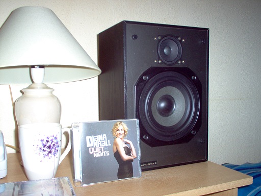
Steve, just trying to follow here, you provide a schematic, simulation and then are
those pictures of the system that you simulated and built? Trying to show the process?
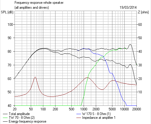
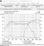
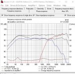
This is how the frequency repsonse looks like now:
Please tell us more about your system, do you have a miniDSP that would allow
you to try different amounts of baffle step?
It looks from the curves as if you need 3 -6 dB of baffle step.
The woofer slope at the crossover point looks strange as if starting at 1st order then
transisitioning to 2nd or maybe 3rd - too lazy to count the dB s. What was the intent
for your crossover, traditional 3rd order or ...?
LSspeaker, you have done a terrific piece of work here IMO.
Looks well done to me.
Issue might be a certain shout at 800Hz:
Ralf fixed that with a presence notch:
Problem might be impedance with a parallel MTM:
That'll take you down to 2 ohms, which might fry your amplifier. My definite conclusion is you should wire the basses series. And take the rest from there.
Hi,
Thanks for all the feedback and the tips.
Drivers used:
- Mid-woofer: HDS-P830883 8ohm
- Tweeter: D2604-833000 4ohm
Cabinet design:
- Woofers in separate vented box
- Tweeter in a separate box
The crossover is a 3th order crossover at the frequency of +-2300Hz,
This crossover point is determined by the distance of the woofers.
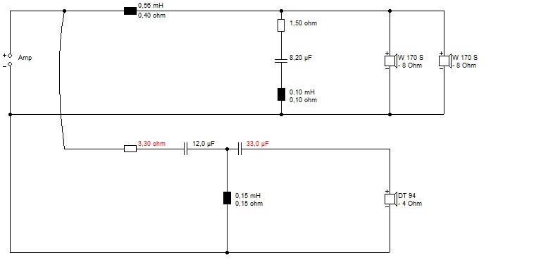
When I was re-studying on my current crossover I noticed the calculated Zobel was way of what it needed to be (something went wrong in the calculations there...)
I'll now implent individual Zobels for each woofer.
After this I'll make new measurements at 1m for overall respons and closer measurement to see what's happening with the phase.
I'll also try to get my hand on the tools to measure the impance of the combined woofers.
When this is done I'll try the 3db baffle step attenuation and remeasure.
From there I'll have to see wether a notch filter is nessasary or not.
I also noticed the crossover frequention wasn't exactly where I wanted it to be, so I'll probably change some values in the current crossover
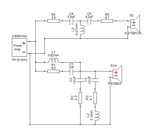
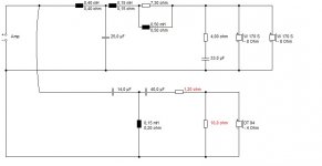
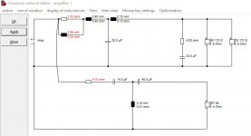
This is the drawing of the new plans for the crossover (changes being the correct zobels and bafflestep):

I now realized I made it a bit hard the way the speakers are set-up for a first speaker-project. I'll see where I get and if it doesn't statisfy I can always just make a simple 2-way out of it.
@system 7:
I don't see a problem for the woofers being connected parrallel, please explain yourself 🙂
Thanks for all the feedback and the tips.
Drivers used:
- Mid-woofer: HDS-P830883 8ohm
- Tweeter: D2604-833000 4ohm
Cabinet design:
- Woofers in separate vented box
- Tweeter in a separate box
The crossover is a 3th order crossover at the frequency of +-2300Hz,
This crossover point is determined by the distance of the woofers.
When I was re-studying on my current crossover I noticed the calculated Zobel was way of what it needed to be (something went wrong in the calculations there...)
I'll now implent individual Zobels for each woofer.
After this I'll make new measurements at 1m for overall respons and closer measurement to see what's happening with the phase.
I'll also try to get my hand on the tools to measure the impance of the combined woofers.
When this is done I'll try the 3db baffle step attenuation and remeasure.
From there I'll have to see wether a notch filter is nessasary or not.
I also noticed the crossover frequention wasn't exactly where I wanted it to be, so I'll probably change some values in the current crossover
This is the drawing of the new plans for the crossover (changes being the correct zobels and bafflestep):
I now realized I made it a bit hard the way the speakers are set-up for a first speaker-project. I'll see where I get and if it doesn't statisfy I can always just make a simple 2-way out of it.
@system 7:
I don't see a problem for the woofers being connected parrallel, please explain yourself 🙂
OK, I think I know what's going on here:
Looks like I'll have to run a sim to tidy it up.
Software | Visaton
Drivers used:
- Mid-woofer: HDS-P830883 8ohm
- Tweeter: D2604-833000 4ohm
There's a good speaker lurking in there. Well done, my friend. 🙂
Looks like I'll have to run a sim to tidy it up.
Software | Visaton
Drivers used:
- Mid-woofer: HDS-P830883 8ohm
- Tweeter: D2604-833000 4ohm
There's a good speaker lurking in there. Well done, my friend. 🙂
I ran this one up the flagpole with some vaguely similar drivers.
Disregard the tweeter frequency response. I was more interested in using a 4 ohm tweeter to see how it worked out electrically.
I also used a bigger Zobel on the woofers. The bafflestep seems to work.
Preliminary findings are the impedance is too low on the tweeter. That should be fixable. But the whole thing seems to work extremely well on the woofers. It seems to be 90 degree phase which is no bad thing on an MTM. BW3 was Joe d'Appolito's original MTM idea.
We'll get there. 🙂
Attachments
Hi,
Thanks for the simulation!
I'm not sure wether the low impedance of the tweeter is a real problem.
I not technical enough too understand the reason of this "too low" impedance, nor know how this can be fixed without changing too much.
Regards
Thanks for the simulation!
I'm not sure wether the low impedance of the tweeter is a real problem.
I not technical enough too understand the reason of this "too low" impedance, nor know how this can be fixed without changing too much.
Regards
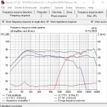
I Did a bit more simming this afternoon. The impedance is improveable without much effort but I wouldn't call this the final article. Messed up phase a bit though. It went more phase aligned.
I also did a 6kHz notch style which seemed to tick the right boxes. The 33uF is fairly optional.
The actual balance is a matter of choice. We have ended up quite monitor flat here. That can be fatiguing in a bare room.
I also did a 6kHz notch style which seemed to tick the right boxes. The 33uF is fairly optional.
The actual balance is a matter of choice. We have ended up quite monitor flat here. That can be fatiguing in a bare room.
Attachments
Steve,
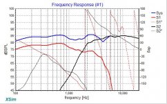
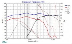
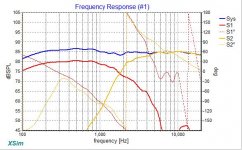
sorry to say it again, but offering detailed simulations based on wrong data is pretty useless. I used your choice of components on my data for the Peerless 830883, the baffle I used is clearly not the same but the data should be still usable. Your first crossover applied to my real data gives this (look only at the woofer FR):

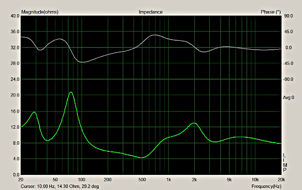
Minimum impedance of 3.65 Ohm at around 200 Hz.
The second crossover is not better, with a minimum impedance of 3.5 Ohm between 200 and 300 Hz:

I think that the following FR looks a bit better, even if it is not completely correct. I used my data for a Seas 27TBFCG tweeter (different driver), and moreover the effect of my baffle on the tweeter is different than the effect of the OP baffle in a MTM design. Minimum impedance of 3.1 Ohm between 300 and 400 Hz. Again look mainly at the woofer curve:

IMHO what has to be done is a complete redesign of the current crossover, but first the OP needs to correctly measure the drivers on the baffle. Without real data we are essentially shooting in the dark.
Ralf
Connecting the two woofers in parallel creates an impedance that dips at less than 4 Ohm, no matter the crossover used. You need a solid 4 Ohm rated amp to drive this combination.
sorry to say it again, but offering detailed simulations based on wrong data is pretty useless. I used your choice of components on my data for the Peerless 830883, the baffle I used is clearly not the same but the data should be still usable. Your first crossover applied to my real data gives this (look only at the woofer FR):
Minimum impedance of 3.65 Ohm at around 200 Hz.
The second crossover is not better, with a minimum impedance of 3.5 Ohm between 200 and 300 Hz:
I think that the following FR looks a bit better, even if it is not completely correct. I used my data for a Seas 27TBFCG tweeter (different driver), and moreover the effect of my baffle on the tweeter is different than the effect of the OP baffle in a MTM design. Minimum impedance of 3.1 Ohm between 300 and 400 Hz. Again look mainly at the woofer curve:
IMHO what has to be done is a complete redesign of the current crossover, but first the OP needs to correctly measure the drivers on the baffle. Without real data we are essentially shooting in the dark.
Ralf
Connecting the two woofers in parallel creates an impedance that dips at less than 4 Ohm, no matter the crossover used. You need a solid 4 Ohm rated amp to drive this combination.
Attachments
Actually, Ralf, I was kinda hoping you'd sort this one out rather than me! 😀
My idea was essentially this:
The 6kHz notch is essentially written in stone for a simple circuit. The only bass variable is the 0.56mH coil size.
I am quite happy to burn my fingers on a soldering iron. Cut them with knives and saws doing woodwork.
Personally I hate 6" speakers. Never sound right to me.
Compound the problems into an parallel 4 ohm MTM and it gets worse. But I do have a responsibility not to blow up amplifiers and burn down people's houses. I might get sued. 😀
- Home
- Loudspeakers
- Multi-Way
- LS2019, time to make these better