TubeLab SPP Questions

Been spending some time (days, not hours) cataloguing the thermionic, sand and driver stash. Already found several goodies I forgot about, e.g. an externally beaten Quad 303 that fired-up after a brief ramp-up on the Variac.
Already received the output and p/s cap from Mouser...yeah, sand!

OK just kidding, although low voltages will work better with four grandchildren under four, so there's that.

Downside is that the Chief Cook & Bottle Washer has seized on this opportunity to force an eBay purge of about a dozen guitar speakers. Rats.

Also found P-P OPTs, including pairs of both Hammond 1608s and Dynaco Z565s (for the ST and SCA-35 EL84 uL amps) amongst others. These in particular are practically begging for a little solder on those old wires.

Questions for George:

(1) are the SPP boards available? Looks like I need a few. Lord knows I'm not doing point-to-point at my age if I can avoid it.

(2) I noticed that on the Dynaco EL-84 amps, the SPLITTER plate and cathode resistors are slightly different values (cathode is about 22% larger, 27K vs 22K), which seems odd.

On the SPP, they are the same (I would say symmetrical), which seems logical. What gives? D. Hafler up to some tricks I can't fathom?

(3) I would like to use one board to make a Flexi-SPP, with off-board Octals for 6V6 and the like. Maybe an octal driver, maybe even 6L6etc family power tubes if I can concoct an easy way to switch OPTs. Any issues with that?

On the SSE with off-board octals for 6AV5s, I neatly tie-wrapped the wires, but didn't twist any, not even the fils. No hum, but probably bad practice.
What SHOULD I do? Just twist the fils, say 3 turns/inch? Twist the whole bundle? Just curious.

(4) What, no CCS on the driver cathode? I found a sleeve of 10M45s in the stash...I can do it off-board like I did on the spit & duct tape Rat Lab 6AV7.

(5) Coupling caps on SE amps seem to cluster around 0.22uF, while P-P amps all seem to use 0.1uF. Why is that? Only dealing with half a wave at a time?

Thanks in advance...

KX750.1

Relay is cycling. I have pulled R35 and amp stays on. Relay comes on.

I have replaced U14 (LM361) and U11 (TL072C), put R35 back in circuit, get the same results. Cycling protection. Pulling R34 back out now.

I have board out of chassis. All PS FET's are new 3205's with 47ohm resistors, and 640's and 9640's are new.

I have 12v across all four zeners.

Voltages of IC's

U14 LM361
Pin 1: 12.03
Pin 2: 0
Pin 3: -7.42
Pin 4: -.452
Pin 5: 0
Pin 6: -11.75
Pin 7: 0
Pin 8: 2.76
Pin 9: -1.30
Pin 10: -1.17
Pin 11: 2.31
Pin 12: 0
Pin 13: 2.81
Pin 14: 2.81

U11 TL072C
Pin 1: 10.12
Pin 2: 28.80
Pin 3: 0
Pin 4: -11.75
Pin 5: .556
Pin 6: .560
Pin 7: 5.61
Pin 8: 12

U13 TL072c
Pin 1: .002
Pin 2: .002
Pin 3: 0
Pin 4: -11.75
Pin 5: 0
Pin 6: .007
Pin 7: .625
Pin 8: 12

Attachments

  • Kicker ZX750.1.jpg
    Kicker ZX750.1.jpg
    1 MB · Views: 88
  • Preamp conn.jpg
    Preamp conn.jpg
    730.2 KB · Views: 83

Rockford Fosgate 800a2 meltdown

I got one for ya.

Appears this thing had a nuclear meltdown of some sorts, and I have no idea what would even cause this amount of damage.

Even more importantly, is it even fixable? anyone have any clear pictures/schematics of the burned section in the TL494 circuit?

it appears on first glance it went into a serious oscillation before it had the meltdown. the Zobel filter is burned. Also, I noticed the transistors have unsoldered themselves from the heatsink indicating this thing got SUPER hot... like firecracker hot.

Pictures are too big to attach them here, so I threw them on Google Drive:
800a2 - Google Drive

thoughts?

LM3886 Bypassing Revisited (applies to other chip amps as well)

In the past decade-and-a-half that has passed since the LM3886 was released, there has been a tremendous development in the area of ceramic capacitors and organic electrolytic caps. So I decided to revisit the bypassing of the LM3886 by running a couple of sims.

The goal here is to have a low supply impedance, basically from DC to daylight. Now, at DC the resistance of PCB traces and wiring connecting the supply to the board sets the limit -- in my sim, the limit is 20 mOhm (20 cm of AWG 20 plus a couple of connectors or terminal blocks). At HF, the self-inductance of the IC package leads limit the impedance. The supply leads on the LM3886 are rather long. There is at least 7~8 mm exposed between the package an the board, and probably at least another 7~8 mm inside the package as well. So a little optimistically, I estimate 15 mm of lead length, resulting in 15 nH of inductance. This means the lowest possible supply impedance at 10 MHz seen by the LM3886 is 1 ohm.

Attached plots show the supply impedance as seen from the LM3886 die looking out through its supply pin. The bypassing in the first picture is a 4.7 uF X7R ceramic capacitor. About 7 mm from the ceramic cap is a 22 uF Panasonic OSCON cap, then 30 mm further away a 1000 uF generic electrolytic can. From this point, the supply is connected through 20 cm (8") of AWG 20 (0.5 mm2) wire. The supply is assumed to be ideal (zero output impedance) as I'm only looking at the decoupling network. Any real supply will only degrade performance.

The second picture shows what would happen if we used two 4.7 uF ceramic caps in parallel. They are physically smaller than the electrolytic cap, so they can be placed closer - 3 mm apart.

Finally, the last picture shows the supply impedance with the bypassing network recommended in the LM3886 data sheet (100 nF film cap, 10 uF tantalum, 1000 uF electrolytic can).

The parasitics for the various components, I obtained by measurements on an HP4194A impedance/gain-phase analyzer and/or from the manufacturer's specs.

As shown, the 4.7 uF ceramic (TDK P/N: FK20X7R1H475K) + 22 uF OSCON (Panasonic P/N: 35SEPF22M) + generic 1000 uF, 35 V electrolytic can provides much better performance than the network recommended in the data sheet. The ceramic cap is $0.86/EA @ QTY=1; the OSCON, $1.05/EA @ QTY = 1 according to Digikey.

Food for thought...

~Tom

Attachments

  • LM3886_Bypassing_4u7_22u_1000u.png
    LM3886_Bypassing_4u7_22u_1000u.png
    49.3 KB · Views: 1,416
  • LM3886_Bypassing_4u7_4u7_1000u.png
    LM3886_Bypassing_4u7_4u7_1000u.png
    63.8 KB · Views: 1,391
  • LM3886_Bypassing_100n_10u_1000u.png
    LM3886_Bypassing_100n_10u_1000u.png
    63.6 KB · Views: 1,375

DD Z1a damaged

Hello, i own a DD Z1a. I have bought this one damaged. As i have opened, i found Power supply Fet´s and Audio Fet´s burned. I have repaired all of them. Changed also the Capacitors in front of the Fets from Power supply and resistors.
The only problem was the Driver Board for the Audio part.
So in that way i had to send it for service. The Service repaired for a lot of money. I got it back, an it was working for about 40 minutes. Full load was also no problem.
After about 40 min., the Audio Fets burned again. I send it back to service, to recheck. They changed the Fets an drive board (Audio Side) again, tested, and after 40 minutes the Parts burned again. The tried twice.

They expect the Coils(transformers) from the digital audio part, but cannot proof or change because not longer available.

In round about two weeks i got the amp back and would try it myself again. Does anyone had this problem allready and can advice?
Anyway i will take of the coils and put them in a bath with varnish for electromotors. If there will be a problem with this coils it should be done with this.

Best regards from Germany
Achim

Help to troubleshoot TI 3251 12V rail issue

Hi !

I have an issue with my TAS3251. Working on my new 2 boards configuration, suddenly on one board, all board's leds went down. This was surprising as there was only a low volume and PS is 20V (voltage on low side for experiments ; but workbench was a bit of a mess, tight wires... maybe my fault).


Schematics is very similar to TI TAS3251, TPA3251, TPA3255 EVM boards.


The 12 rail is NOK: it starts a about only 3V at powering and then slowly drops to 1V in about 10s. I quickly unplug the PS. TAS3251 FAULT Led is ON (which may be related to the fact that the 12V is NOK):
- 15V is OK
- If I put my finger on the TAS351, it gets hot,
- If I open the jumper after the LM2940 12V regulator, the 12V is OK,
- the 3.3V section looks OK, as my microcontroller get the associated led blink as long as there is sufficient voltage on the 3.3 section (powered from the 12V rail ; about 10s)


I fear an issue in the TAS3251 GVDD circuit with a shortcut to GND.

Did something similar happened to some of you ? Up to now, I had found that this chip was fairly resilient...

Do you have troubleshooting ideas I could experiment, before trying to change the TAS3251?

I could unsolder the 3.3V regulator to decouple the 3.3V section to make sure.


Are there meaningful controls I can do on the unpowered board with a multimeter (resistance/load measurements, continuity checks)?


Help very welcomed !


Best regards,


JMF

Creek CAS 4040 problems and speaker coupling electrolytic query

Hi folks,
I've owned this amp since '84 and recently decided to recap it with Panasonic audio grade electrolytics, on doing so i noticed a slightly cooked 1/2 watt resistor in the driver stage of one channel. The amp seems to sound fine, i can't detect any difference between channels, so for the meantime i upgraded the resistors to 1W metal films and the unit is in daily use. But the supply volts are down about 10 percent in 1 channel because of this so i think it needs to be sorted.The amp could have been this way for years, or even from new! I did lift the outputs off the heatsink and they do not overheat on idle so i think it is the driver stage. I fitted new darlington o/p's and the BC639 drivers but to no avail. I only have a slightly wrong cct kindly sent by Creek, but it is a poor scan and is blurred, hence i cannot give a cct ref for the 1K resistor. Mine is the 2nd version with the phono socket on the phono i/p and not the early one with 5 pin din. Has anyone got a better cct diagramme?
Also i would like to renew the speaker coupling capacitors, they are marked; Rubycon 3300uF, 35V, CEW, what is the best modern equivalents and where to obtain. I have access to CPC and RS components. If anyone has any ideas, they would be most appreciated.

Replacement Terminal for Threshold S500 II

Hello everybody,

I am quite new to the HIFI world and was fortunate enough to inherit an old Threshold S500 from my dad. It was gathering dust in the basement for many many years until I found it and it still works great! Unfortunately one of the terminals seem to be broken (see picture below). Does anyone have recommendations which terminals i should replace them with? And has anyone attempted to replace those terminals on a Threshold before and can share some tips on how to do it?

Thank you and best regards
Duy

Attachments

  • IMG_4238.jpg
    IMG_4238.jpg
    1,004.2 KB · Views: 118

Portable speaker project

Hello,

I am in need of a new portable speaker and I thought it would be fun to make one myself.
It's supposed to become a big one. Not JBL Charge scale, JBL Boombox scale. Because why not? When I was searching for some cheap but decent mid woofers I realized I actually have two 7" Dayton Audio Esoteric ES180Ti-4's laying around. Because I was planning on using those in my main speakers back when my knowledge was limited. Costing about €150 each when I bought them and being not the best but wuite high performance they're EXTREMELY overkill for a portable speaker. Though I don't have any other use for them so why not?

As passive radiators I was thinking of using two SB-Acoustics SB15SFCR-00 5 x 8". They seems to pair quite well with the drivers. F3 of 40 Hz which I think is quite awsome from a 22,5 L portable speakers, decent impuls response and the excursion of both the drivers and passive radiators is very well controled. Though I don't have any experience with passive radiators, does this look reasonable? However I've got to mention that the software is off compared to the given speciafications of the driver. The software thinks they are 7 dB more efficient than they are and that the have a Mms of 131 g, which is actually 27. And the force factor is 21,2 instead of 9,6. Someone know what is causing this? Because then it's probably not simulating the enclosures performance correctly as well.

As the tweeters I was thinking about the SB-Acoustics SB26STCN. It's an inexpensive tweeter with a small faceplate which is ideal for a portable speaker. Obviously it doesn't perform like a Satori but it seems very decent. Like one would come to expect from SB. And anyway, it's a portably speaker, the performance isn't that critical.

Though what I'm mainly looking for now is amplification. I need four channels with chargeable battery, bluetooth and DSP. I know of the Dayton Audio boards but the problem is that their battery pack is 12 V, not 24 V which I've read greatly limits the amps performance. Anyone know a better option? Or a way to make a big 24 V power supply?

Thanks

Building the VTA, tubes4hifi PH16 Phono Stage

Just in case anyone is interested, i am planning to put on here the progress of my build of a Tubes4hifi PH16 Phono amp Vacuum Tube Audio PH16 phono preamp

Just a quick bit about me, I have not picked up a soldering iron for about 30 years so this will be a warts and all description, Hopefully to help anyone else who is thinking of starting a "kit Build" and is worried that it could be a bit daunting.

I will be placing at the end the itemised full cost in time and money to build

After quite a bit of research, I decided on the PH16 and as Roy was helpful with my initial questions.

As I am in the UK I have ordered just the parts kit so the transformer and enclosure will be sourced here, but am planning to make this look a bit different to usual diy valve amps.

The kit has arrived, and i have bought a new solder station from maplins, I have also ordered a toroidal transformer from Terry at Canterbury Windings Home
here are all the parts and where it will be built.

Would be grateful for any advice and will be happy to answer any questions as i go.

Attachments

  • IMG_1385.jpg
    IMG_1385.jpg
    674.4 KB · Views: 2,926
  • IMG_1386.jpg
    IMG_1386.jpg
    343.9 KB · Views: 2,753

ultra low noise 24v dv 2 pin 40x40 mm fan

ultra low noise 24v dc 2 pin 40x40 mm fan

I bought a class d amp from gear4music 2x226 watt in 8 ohm

I expected the fan to be noisy, it is, air noise from the back grill (a bit high rpm), and coilwhine,high pitched noise.

I took the fan out of the case (one rubber dampening screw or what ever it's called got damaged, the end that's on the rear, with the grill in the middle and then the fan).

I want an ultra low noise 24v dv 2 pin 40x40 mm fan but which ?

noise blocker makes a 4020-5500-24 fan but where to get it ?
blacknoise.com - Blacknoise NB-IP55-Series 4020

Stock fan way to high rpm and coilwhine (thank god it was from the fan and not something else)
a6r50HB.jpg

How to properly amp my future speakers

Hello everyone,

I'm in the process of selecting and building a set of high-end speakers. So far, I have two probable choices – Troels Gravelsen's The-Loudspeaker-III, or his Faital 3-Way Classic.

I've refrained from planning on an amp in advance as I want it to be custom tailored to the speakers I'll end up building. Which probably will be one of the two mentioned above. As I'm now finishing an approximate budget for building my new system, I'd like to have some advices regarding amp choices.

The-Loudspeaker-III has an active subwoofer, powered by a Hypex Fusion FA251, while the mid-woofer and tweeter are passive. Does it mean I'll need to bi-amp the speakers? The website states 'the Hypex is fed from the crossover, so no need for a line signal, does this mean no bi-amping? Sorry if it's a stupid question, you never know until you ask.

The Faital 3-Way has its subwoofer in a separate enclosure, so it'll need bi-amping. It's fully passive.

Both speakers are very efficient, only requiring 15watts per channels.
I've made my own research but I'm still unsure I'll be making the right choice without asking.

I'm looking for a good, preferably unexpensive (to start off), way to properly power these speakers with the clean signal they deserve.

Paradigm Ultracube 10 repair notes

Hi,
I fixed one of these the other month, seems to be a common problem with switch-mode power supply capacitors failing, resulting in the sub not powering on or 'clicking' - PSU tries to start then shuts off.

I used a Philips LCR meter to measure capacitors in circuit, for capacitance and D (tan theta). The following ones below marked (*) were deemed duff and replaced:

PSU/power PCB caps:
Mains cap 560uF 400V. Measured 466uF D=0.2
C70 10uF 35V. Measured 5.5uF D=1.4 (*)
C72 10uF 35V. Measured 8.7uF D=0.5 (* - marginal and in a critical part of PSU)
C44 22uF 35V. Measured 14uF D=0.4
C33 22uF 35V. Measured 16uF D=0.3
C29 22uF 35V. Measured 13uF D=1.2 (*)
C27 22uF 35V. Measured 13uF D=1.5 (*)
C28 22uF 35V. Measured 7uF D=1.1 (*)
C15 22uF 35V. Measured 17uF D=0.2

Preamp PCB caps:
C53 22uF 35V. Measured 14uF D=0.2
C53' (not on PCB, glued to C53, unable to read case). Measured 10uF D=0.5, assume OK
C34 10uF 35V. Measured 10uF D=0.3
C24 10uF 35V. Measured 11uF
C32 22uF 35V. Measured 18uF
C7 10uF 35V. Measured 12uF
C52' (not on PCB, glued to C52, unable to read case). Measured 29uF D=0.3, assume is 33uF so OK.
C33 10uF 35V. Measured 11uF
C25 220uF 25V. Measured 195uF D=0.3


Powered on all fine again.
HTH,
John

Luxman DZ-112 Cd Player, erratic disc tray?

Hi All.


I have a Luxman DZ-112 Cd Player in good condition with the exception of the erratic disc tray.


When you press the "Open" button, 80% of the time the tray opens, and then immediately closes.


When I persist, I'll be lucky for the tray to remain open.


Apart from dust, an inspection of the internals doesn't show up anything obviously damaged. The rubber belt appears in good condition and the light lubricant on the plastic cog hasn't dried up.


I was hoping for suggestions as to the likely cause and remedy of the problem.


Cheers


Cliff

Coral Beta 12

I found an article from Chris Templer at TNT about a modified horn cabinet. I have a pair of 12" Goodmans Axiom 201, so I started to plan for this project with my friend and carpenter Ulf. The horn is made out of 32mm MDF with oak veneer that is white washed. The lip at the bottom help the horn to couple to the floor and increase the bass . I will get som lower castors to bring the cabinet down a few centimeters. No filter needed as the sound is great in my ears and a 10m double folded bass horn, Audax 15" is helping out in the lowest low. I run this on my vintage Sony TA-2000F and TA-3200F but planning for a tube amplifier soon.

Coral Beta 12 horn | Flickr

Today versus Yesterday in regard to Thiele/Small Parameters of subwoofers

I was into car audio and home theatre sound systems between the early 1990's up until the early 2000's, in my teens and 20's. My main focus was really into car audio, with subwoofers specifically. I am from the Pittsburgh area. I can remember that there were about 4-5 private car audio businesses and Circuit City and Best Buy in an area just northwest of Pittsburgh. Each of the multiple businesses offered a different variety of subwoofers for each car. I also remember the Crutchfield catalogs from that time too. I can remember the companies that offered such equipment like MTX, Orion, US Amps, Autotek, Cerwin Vega, Kicker, Phoenix Gold, Polk, Kenwood, Sony, Pioneer, Soundstream, Rockford Fosgate, Alpine, Infinity, Bazooka, Profile, etc... It seemed like in my home town, that MTX was the king and everyone had either MTX Thunderpros or Thundercast subwoofers.

Back in the early to mid 1990's, it seemed that very large ported and moderately large bandpass boxes were the king and queen in the car audio community. Many of the cars that these subwoofers were going into were older cars from the 1960's up until the early 1990's. These older cars often had very large trunks. Also 25-30 years ago, I can remember amplifier power costed between $2-$5 per watt. Due to the high cost of amplifier power, it seemed that speaker companies were putting out subwoofers that had a very high sensitivity ratings that often required large ported or bandpass boxes in order to get more spL.

In the early to mid 1990's, I can recall two companies that often reported very high sensitivity ratings for the subwoofers, and they were JBL and Cerwin Vega in the range of 92db-98db for their 8, 10, 12, and 15 inch subs. Most of my knowledge from speakers came from those early Crutchfield catalogs, and what was in online forums. It seemed that Kicker and Cerwin Vega put out the best subwoofers in those catalogs at that time. I remember if you wanted great transient response or so called "tight" bass you went with the Kicker Competition line. If you wanted very high output with a given wattage output, then you went with the Cerwin Vega XL subs. I can remember that the Kicker Comp subs requiring a moderately sized sealed boxes and the Cerwin Vegas needing large ported boxes.


Then something happened in 1996. I was reading a car audio magazine, and Kicker introduced the Solobaric line which mimicked the loaded Isobaric type subs. These subs doubled their cone mass and increased motor strength allowing them to go into boxes half the size of their Kicker COMP line. At the same time, POLK audio introduced their DB line of subs that also went into very small sealed boxes. These newer heavy massed cone subs were put on the market because trunk space was getting smaller with newer cars, and also amplifier power cost dropped in price as well. It seemed that these new very small sealed box subwoofers had a very very LOW sensitivity rating compared to regular subs. It seemed that the market was ripe for customers wanting to put subs into their tiny trunks... or just will not put a larger box in the trunk.


I have had various subwoofer systems in my 1986 Buick Somerset in the late 90's. I had four CV XL's 12 inch subs in 2 cu foot a piece tuned to 36hz hooked up to an Autotek 90 Mean Machine at 400 watts. The CV XL's power handling was about 250-300w RMS. I absolutely loved the sound of my Vegas. My buddy had a 1986 Dodge Lancer Hatchback with two Kicker Comp 15's in a 6.8cu ft. box powered by an Autotek 90 bridged at 2ohms(the amp wasn't 1ohm stable and he had problems with it). The sound from those 15's were amazing, so I sold my CV 12's and got two Kicker Comp 15's. However, I didn't take into account that his hatchback was a lot different from my coupe in terms of sound transfer function. IMO, it seemed that the Kicker 15's lacked a "Full" forceful sound, and that they sounded "Hollow" to me. I can remember wishing to myself that CV would come out with a version of their XL's that would handle a lot more power. In 1996, CV came out with their Vega V-Flex sub, which is my favorite speaker of all time. It seemed like they added a little more mass to the cone dropping the sensitivity rating by 2db, but also dropped the Fs rating too. It seemed like those 12 inch CV Vega V-Flex subs could keep up with or flat out outperform any other 15 inch speaker out there. I tested this by using my Autotek 90 bridged at 4ohms for the Kicker 15 and the CV V-Flex 12. The Kicker in 3.5cubic feet sealed and the Vega V-Flex in 2.2 cubic feet ported. The CV Vega V-Flex was a lot louder, sounded deeper, and fuller. It also seemed to "almost" have the same transient response of the Kicker 15. Then I had two CV Vega/V-Flex 12's in 2.75 cubic feet a piece(28hz tuned), which increased their deep bass between 25-45hz, but very little above 55hz. Then I thought, if the 12 inch Vega could be louder than any other 15, then their 15 inch CV Vega/V-Flex would be just as loud as an 18inch from another company. So I then put two Vega/V-Flex 15's in a 9 cubic foot ported box with a 96 cubic inch port area tuned to 28hz. I then hooked up a US 400 X Exterminator Amp rated at 1600w at 4ohms bridged, but probably put out 2100w from what other sources said. I was going after the loudest and deepest trunk system in the area, and I achieved that hitting around 149-151db at certain times/frequencies. I can remember plugging up the port if I wanted to play any "Chopped and Screwed" deep bass tracks, and it sounded great that way too.

I am asking if sensitivity has anything to do with the output for a speaker? I have talked with many people about this, and some say it doesn't matter that much, if at all. Others say it has a lot to do with the output that you want. I have also read that many of these sensitivity ratings are often inflated by companies. In the past(before early 2000's), it seemed that the sensitivity rating was a big deal when buying a speaker. Now it just seems that kids are into How much power a speaker can handle. I also read that many of these sensitivity ratings are measured when the subwoofer is playing a 1000hz tone, which is inaccurate/irrelevant, as most subs are played between 10hz-100hz. Many newer companies don't even list the DB rating for their subs, only their POWER handling.

Back in the day, I can recall that if your speaker had a QTS of .45-.8 then you would put it into a sealed box or 4th order BP. If your speaker had a QTS of .18 up to .4 then you placed it into a ported/vented box or 6th order BP. This was pretty iron clad... I can recall putting a higher QTS speaker like a Kicker Comp 12(that required a 1.75cu ft sealed box) into a large 2.75 cu ft ported box.. and the bass sounded really muddy, ringing, lacking punch, and sounded horrible because they were underdamped. Then I remember my friend got two CV XL 15's(a low QTS woofer that needed 4cu ft ported per), and put them into a 8 cu ft sealed box, and I can remember not hearing any low bass at all, as the FB and Fs was way too high and lacked output because it was way overdamped.

I take a break for a few years, and now I see all these subwoofers with HUGE surrounds like a DONUT! I see these massive looking cones with gigantic dust caps. I am used to seeing normal sized dust caps and surrounds. It seems as if the new kids on the block only care about Power Handling and XMAX with large structural features.

Now I see all these newer companies out. Many of these newer and of higher quality. However, I am seeing many companies are using high to very high QTS subwoofers being put into very large ported or 6th order boxes. I know that you can place a high QTS sub into a ported box, but it will not have the same snap and transient response as a low QTS in a ported box. What gives? Is it because people want very LOW bass, and would prefer the thick sound of a higher QTS sub in a ported box?

I sat inside a kid's VW Golf that had a 12 inch Kicker L7 sub in a 2 cubic foot box hooked up to 600 watts, and the sound was very loud, but the transient response is just ok. The Kicker L7 12 has a QTS of .692. I am very confused about today's use of high QTS subs in ported boxes??? I am finding that many companies are doing the same thing! I am looking at certain new Cerwin Vega subwoofers that have a much higher QTS than their older lines.. but still recommend ported boxes.


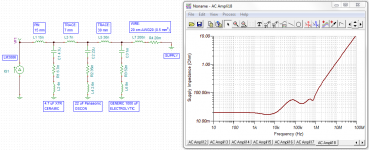
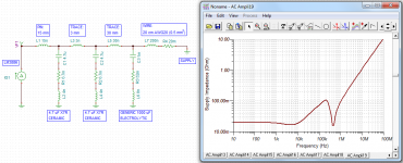
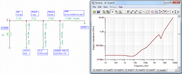
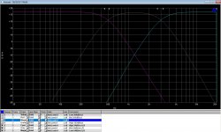
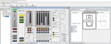
I have been playing around with enclosure modeling software, and that many of these newer speakers often will not fit into the boxes that their Thiele and Small parameters suggest. I often find that the speaker box is either gigantic, spot on, or extremely small/tiny.

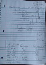
I have been looking into Digital Designs (DD) subwoofers, as these subs seem to be regarded as great quality and of high SPL winning many comps. About 75% of their product line recommends that their speakers are to be placed in large ported boxes. So I am looking at their Redline 700, Redline 800, 9500, and 9900 series subwoofers. I can remember that Cerwin Vega XLs used to have a QTS between .27-.36 for their 8-15 inch subs, and they required ported boxes. So all of CV XL line were low QTS subs. With the CV XL subs, Even though the group delay from the port was apparent, the transient response of the CV subwoofer itself was almost the same as the Kicker Comp sub. Try playing the song by the Beastie Boys called "Paul Revere" on different types of subs. It seems that these other newer companies vary their QTS, VAS, and FS a great deal within their own line of speakers. I do not understand this. I notice that the 10 inch subs have a much lower QTS compared to their larger brothers. I'll give an example of the DD 9500 and Redline 700 line with corresponding QTS, FS, and VAS for each size:

9500 line:

DD 9518 QTS .716 FS 30hz VAS 97 liters
DD 9515 QTS .666 FS 39hz VAS 52 liters
DD 9512 QTS .662 FS 37hz VAS 26 liters
DD 9510 QTS .431 FS 37hz VAS 19 liters

Redline 700 line:

DD 718 QTS .523 FS 26hz VAS 170 liters
DD 715 QTS .537 FS 31hz VAS 70 liters
DD 712 QTS .434 FS 28hz VAS 39 liters
DD 710 QTS .321 FS 28hz VAS 21 liters


When I plug in the specs of the 700 line into software, I get the most massive box for the 18 inch sub at 9-14 cubic feet.... and then the tiniest box for the 10 inch sub at .35 to .5 cubic feet per sub. Another example is the 9518 18 inch sub needing 10-23 cubic feet of ported per sub. Then I plug the 9510 ten inch sub into software, and I get .7 to .85 cubic feet per sub?? What gives?


I find this so confusing. However, their recommendation for the size of their boxes increase at a small linear rate as the subwoofer gets bigger. However, all sorts of modeling software shows a drastic difference between their smallest to largest sub. It seems that their 12 and 15 inch subs are the only two needing a normal sized box.

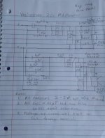
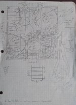
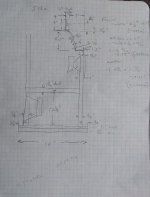
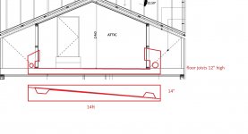
I am looking into large ported boxes, but mainly 6th order series bandpass boxes because of the type of car that I may be buying like the Lexus SC300 or Nissan Skyline R33 GTR.

So what is the story now days? What changed in the last 20 years? I used DD Audio as an example. Are there any other newer sound companies out there that produce a subwoofer similar to the old Cerwin Vega XL's or V-Flex that have a lightweight cone, low QTS, low FS, etc..?

Sorry for being so long winded. I've had 20 years of questions.. and I needed to put the background of where I came from in the picture.

Brad

Which is the better tweeter budget Klipsch speakers or a Peerless unit(metal horns)

Just a random question but I'd just like to get some general thoughts on it. What would you rank as the better tweeter?

I'm building a speaker and I have used the Peerless in another project which I actually really like the sound of, however, I want to build another small scale mini monitor speaker this time and use a horn tweeter (and metal), because I like them.

Anyway I've tried the Klipsch budget speakers in the past and really liked those (the r-41m), it had such a live music sound to it and I'm putting it down to the horn they use, as I didn't think it was a really special speaker overall. The mid bass I believe was the let down and obviously lightweight chipboard cabinet. The cabinet actually wasn't that bad chipboard isn't the worst material if you ask me, possibly better and livelier than MDF but pros and cons, MDF is far denser better for bass, but they both fail miserably compare to ply, just my opinion.

In your opinions though is the Peerless a better, as good as, worse than what Klipsch give in they're budget mini monitors?

Here's the Peerless

Peerless by Tymphany H25TG05-04 1" Titanium Dome Tweeter with Waveguide 4 Ohm

And I have no idea of the Klipsch specs apart from they are 90º x 90º TRACTRIX HORNS, Aluminium.

Speakers, Headphones, and Premium Home Audio | Klipsch

DB Technologies PA 3.0 Problem

Hello everyone
Yesterday i bought a used db pa 3.0
When checking at Sellers home It seems It was working well
But when i try at home, even without any input attached It makes a big "Buzz sound"
Tried to switch cables / speakers / Power outlet and send some input, the speakers works but i jeep hearing this vert loud buzz
Amplifier also make a strange sound when i turni It on as on following video where you can also hear the buzz

db pa 3.0 - YouTube

What May Be the problem?
Also che Power cables has been fixed by Seller like per pic
16100139383634442770059954846689.jpg

Does heater phase matter?

This may be a dumb question, I'm not sure. I'm on my second tube amp build and starting to thinking a bit harder about the details. Here goes:

In regards to noise, does the heater phase matter?
For example, lets say I have a two stage SE preamp.
First stage is a grounded grid which runs into a cathode follower- oldest topology in the book probably.
Now let's say I have two heater windings both as part of the main power transformer.
On the grounded grid stage I have the heater windings in one phase, but the cathode stage heater windings are flipped, so 180 degrees out of phase with the first stage. Would I get noise cancellation benefit in 60Hz, but also possibly in 120/180/240/300?

Seems that there can be some way to benefit from hum cancellation even in a SE preamp, especially if there are two stages. I tried searching but I haven't found too much talk of this.

Transformer Magnetic Coupling - 60Hz on one channel of brand new build, am I SOL?

Looking for some advice, pretty disappointed in the conclusion I am coming to.

Just finished a very involved 45 parafeed dedicated headphone amplifier using Sowter transformers. The mains is a custom job by them, pictures below.

Mains and output transformers are oriented 90 degrees to one another. The left channel is completely silent. The right has a VERY audible 60Hz buzz. Shorting the inputs has no effect, neither does shorting the input tube grid to ground, or removing the input tubes entirely. I've isolated it to the output stage, and it persists even with no tubes in the amp, leading me to believe it is magnetic coupling from the mains transformer, despite the orientation.

Short of rebuilding the amplifier, is there anything that can be done? A lot of work went into this build, so a pretty disappointing outcome. The sound is great otherwise, but as a headphone amp, it is very loud in the right channel, can be heard easily above music playing.

Thanks for the help.

Attachments

  • DSCF5573.jpg
    DSCF5573.jpg
    862.7 KB · Views: 282
  • DSCF5575.jpg
    DSCF5575.jpg
    825 KB · Views: 280
  • DSCF5581.jpg
    DSCF5581.jpg
    283 KB · Views: 264

How does delta sigma dac work inside

In attempt to design a DAC, i want to understand more about delta sigma building block inside, i have read quite some article about this and have an overview of it but there are still many things concern me:
1.For simple DAC like pcm5102, there are digital ground, charge pump ground and analog ground. This one doesn't use and external opamp as analog filter so what does the analog supply for? I think it supply current for an opamp inside the DAC to do the IV work?
2. For more complex DAC like es90x8Q2m, there are seperate Vref for Left and Right channel, as i understand, the vref is use as voltage reference for delta sigma modulator to compare to the input bitstream, but isn't that digital part and why need seperate reference for left and right channel?
Thanks!.

Vandersteen 2Ci Design Overview and XO Schematic

I reverse engineered the Vandersteen 2Ci back in 1994 and am posting the crossover
schematics here in order to help others that have problems with burnt out resistors and
for general educational purposes. I never intended to post these in public and never
redrew them with CAD tools. I chose to show how component values were built up from
smaller values, obviously it can be redrawn with some simplifications.
Don Keele's extensive review of the 2Ci in the June 1992 issue of Audio page 73 in the .pdf:
https://www.americanradiohistory.com/Archive-All-Audio/Archive-Audio/90s/Audio-1992-06.pdf

Stereophile measurements of the 2Ci unfortunately before he got better measurement gear:
Vandersteen 2C loudspeaker Measurements | Stereophile.com

The 2 series has gone through several model revisions over the years including parts
changes even with the suffix retained such as 2Ci. From what I remember speaking
to RV the rear plate has Model 2 written on it but the serial number will end in a letter
if it is a later model. My serial numbers end in i for example.
Mine have 1" Audax ferro fluid cooled tweeters, Peerless poly cone mids that look
exactly like the 821615, custom Vandersteen 8P2C woofers and a stamped frame
acoustic coupler. Both woofers have rubber edges and the mid has a plastic edge -
no foam.
Peerless 821615 midrange spec sheet:
http://www.madisound.com/pdf/peerless/821615.pdf

First is the mid/tweeter crossover, it can be seen to be a simple 1st order cap to the
tweeter, one ohm fixed resistor pad, an Lpad, a shunt 20 ohm fixed R, and an RLC
with a resonance at 918 Hz - very basic.
The mid also has basic HP and LP first order filters with an Lpad and some shunt
resistance to flatten the driver impedance.

Second is the woofer/coupler crossover with a 2.8 mH inductor providing some baffle
step and a total of 554uF HP to the main 8" woofer and a huge 20 mH inductor to the
10" acoustic coupler (AC) assist. They share a common air cavity with the AC coupled
like a passive radiator but with drive to boost the output. Keele, in his Audio Review
confirmed this by disconnecting the AC and noting the change in output level around
Fb, the box AC resonance. That was 38 Hz from memory and the boost was something
like 3 or 5 dB - I have to look it up to confirm. The AC has a thermal switch in series
that trips at about 5 minutes into a bass heavy track played at a level that I like, it is
also close to the displacement limit of the main woofer. Some say that the switch
doesn't age well and the trip point lowers and suggest removing them. Note that in
the next post the picture of the woofer inductor has the number 3 on it and I seem to
remember it being 3 mH. I'm not sure why my notes have 2.8 mH instead.

Third is a pictorial layout of the double sided circuit board which is glued in and very
difficult to remove so I didn't. I used an ohm meter to confirm how the traces are
connected.

Fourth is a side view where I measured the driver offsets in order to enter them into
CALSOD, the program I used to model the system.

Fifth is a front view providing the height positions of each driver also for use in the
CALSOD program.

Attachments

  • VAN 2Ci MT XO.jpg
    VAN 2Ci MT XO.jpg
    112.2 KB · Views: 798
  • VAN 2Ci W XO.jpg
    VAN 2Ci W XO.jpg
    115.3 KB · Views: 787
  • VAN 2Ci XO PICTORIAL.jpg
    VAN 2Ci XO PICTORIAL.jpg
    141.2 KB · Views: 904
  • VAN 2Ci SIDE.jpg
    VAN 2Ci SIDE.jpg
    117.6 KB · Views: 747
  • VAN 2Ci FRONT.jpg
    VAN 2Ci FRONT.jpg
    95.3 KB · Views: 775

FS:Agilent 34401A/53131A Fluke 287C GW Instek LCR(Ebay)

1、Agilent 34401A Digital Multimeter
Agilent 34401A Digital Multimeter | eBay

The function is used normally and there is no maintenance history inside. However, the fixed buckle of the handle fails, and it is currently free to move, and the handle cannot be fixed at any position.

2、Fluke 287C
Fluke 287C | eBay

3、Agilent 53131A 225MHz Universal Counter
Agilent 53131A 225MHz Universal Counter | eBay

4、GW Instek LCR-829 LCR Meter
GW Instek LCR-829 LCR Meter OPT-01 | eBay

Need construction advice for OB

I'm very interested in hearing people's advice as I'm in the process of building a set of open baffles (first time speaker builder). I already have a pair of full range Lii Audio Crystal 10's mounted on 15 x 19 inch solid maple baffles and burning in (close to 100 hours).
Lii.jpg
I'm waiting on a pair of Acoustic Elegance Dipole15 - Dual-8ohm drivers to show up in a week or so. I want to mount them on 24 (W) x 36 (H) inch solid maple baffles. Should they be centered as much as possible on 3 sides or off centered and how far from the bottom? I understand there aren't many options due to the fact that the baffle will only be 24 inches wide.
I have a Primare A32 power amp. Here's a rear pic.
A32.jpg
Since I have 2 sets of speaker inputs on the power amp, I was thinking of running the Crystal 10's to the top speaker inputs without crossovers (that's how they're being played now) and the AE woofers to the bottom speaker inputs. I know I'll need an inductor on the woofers to keep high frequencies from going to them. I need to know if that hook up will work without harming the amp or speakers. If that hook up will be okay I'll have more questions. Thanks for any advice.

Ammocan build with Dayton and Tangband

I have a PA70 Ammocan (11x16x5.5 fr 5.6 ft3) and trying to figure which would be best for my drivers. I have in my possession,

Dayton dc160-8ohm 6.5" woofer
or also have the

Dayton DCS165-4ohm subwoofer


Either of those to be paired with

Tang Band 1320sj 8ohm full range bamboo 4" driver

Dayton DC28FS-8ohm silk dome tweet


My concerns are the Dayton sub is is 4ohm and the other drivers are 8 ohm and me being a noob, not knowing how compatible that will be.
I'd likely use a Nobsound 2x50+100 bluetooth amp. The amp is the only piece I do not yet have. I am using an active 3 way crossover.


Which 6.5" driver? Vent the can and use the subwoofer? Or Use Dayton's PR215 8" Passive Radiator on the back of the can with the DC160? Or the DC160 alone?

Dynakit ST-70 high Voltage readings

Dynakit St-70

Short stack PA060
Yellow sheet mod (2 x 1N4007) on rectifier
Selenium rectifier has been replace with a 1N4007 also
5AR4 Mullard still in use
7199 still being used

Bias caps have been replaced
Upgraded Cap Can has been replaced

PCB board still has much of its stock circuit

In the manual I was checking the Voltage points after the amp was warmed up
All my voltages were high

I expected the increase because of the previous 117 it expected was now getting 122.5 AC V from modern increases

Some numbers

EH L34
Pin 3/4- 460dc volts

5ar4
Pin 2/8 - 473 volts
390AC it is seeing
But the 1N4007 diodes are cutting it down to
203 AC

Seems pretty high. Has anyone else read higher voltage on theirs?

KT88 Valve Tube Amplifier Single-ended Amp DIY KIT from China. No instructions!

Hi All!

So a good friend of mine bought himself a valve amplifier kit, something i have never done before, he wants some help and i like a challenge

I have restored and rebuilt a leak stereo 20, leak tl12 plus, quad ii etc but never done point to point amplifier build or from scratch.

This is the kit:

KT88 Valve Tube Amplifier Single-ended Class A Stereo HiFi Amp DIY KIT 16W+16W | eBay


And the instructions it came with are rubbish!

9G7zrBO.jpg


I mean seriously how lacking is this?

HGPT1JL.jpg


I decided to make a start by putting on what i could.

eZza82i.jpg


z2nXhtx.jpg


z2nXhtx.jpg


ejTm9MF.jpg


Now because of the lack of instructions i decided to email the seller, this is what he sent me for help, pictures of it built!

wkX1vMh.jpg


pyU8Z45.jpg


KiaiAbW.jpg


Q2EYMsh.jpg


Now don't get me wrong this kind of helps but when i tried to match this to the circuit diagram theres a few things missing.

list of parts

NiVnkF6.jpg


wYqaKde.jpg


My attempt of putting some instructions together to show where and how the components solder in.

53596S1.jpg


Where i got stuck is the input/preamp stages 6n8p, It shows 8 pins being used in the diagram and a jumper wire being used, but this isnt in the circuit digram, the pin arrangement seem odd like it's not in order.

Also finding where all the earthing/ground wires are and go, there are so many!

can someone with experience tell me if the pictures of the built amplifier match the circuit diagram? And should i try to match and copy what i see in the built pictures?

Thanks!

Open baffle without limits

Hi all,

I'm an audio pro in the early stages of learning about open baffle designs and will soon be trying some experiments. I know that open baffle speakers present some unique opportunities and challenges but I wanted to ask a question.

In a world without limits what would a possible "perfect" open baffle system look like? I'm talking a world where space is not an issue, the room can acoustically treated to optimize the performance, any drivers are available, any baffle size etc etc.

I'm imagining a 3 or 4 way system with ATC mids, fully active, DSP crossover, as much amp power as is needed. There's also no limit to driver count… how about 4 x 15" drivers for the bottom few octaves? You get where I'm going with this.

Thanks!

Cad new Yamaha CR-2020 capacitor board

Hi,

My first post here.

I have bought a vintage amp (cr-2020) at an auction.
I am familiar with electronics but mostly digital electronics. But I have also made five or so recappings of other vintage amps so I do have experience.

In the Yamaha it turns out that the e-cap pcb is in very bad shape, so I started to cad a new board in KiCad. Then it hit me that someone might have done this before.

Do anyone of you know if it has been done already the e-cap pcb for the cr-2020?

ICEpower ASP500 kit from Ghent and module from PartsXpress

Put together seems pretty self explanatory as no detailed direction is offered from Ghent or Parts Express.

I'm left with 2 questions:

The harness for xlr connection has a shielded cable at one end which has 2 wires and a surrounding stranded shield for the neutrik connect, 1,2,and 3 ground, positive, negative respectively. However, at the other end of the jst harness there is a lengthy grey wire. Would this connect to the star chassis ground or ground tab hanging off the neutrik connect?

Also the kit didn't come with an led bulb and I'm wondering where on the snall dimmer led pcb board does the two leg of the led bulb get soldered to? There are several through holes open there.

Thanks in advance.

Yamaha PSR 6700 switches on but no sound coming out,display ok, amplifier ok

Helo,guys !

I have a Yamaha PSR 6700 that after a general 220V power failure in the whole studio , power on but no more sounds. Power amplifier is working good, tested on RCA inputs. Display is working good, all functions seems to be ok only that is no more output (or input in amplifier stage).

I think maybe somebody else faced that problem before and gain some experience.

Any help would be appreciated.

Thanks in advance

Attachments

  • PSR6700_CD3_E-cut-01.jpg
    PSR6700_CD3_E-cut-01.jpg
    901.4 KB · Views: 79

  • Locked
Your Dream PA: What In Your Wildest Dreams Be The Best PA?

Specifications:

Battery powered

Light weight

No wires

No active crossover needed.

High powered

Automatic dynamic room EQ

No monitors required

Configurable selectable presets for each song.

Indestructible drivers

Auto mixing and instant live mastering and recording.

Woofers no bigger than 8".

No stage amps. Guitar players can call up their effects with a virtual pedal board.

PA can be programmed to run the lights.

Drums instantly processed so even the worst sounding drums can sound acceptable. The drum mics can be switched to triggers.

The question is, with today's technology how much of this is possible?

What's your dream PA?

The Definite full range guide/helper

Hello guys, long time I’ve been away but not much has changed.
I’m getting away from building some speakers with china parts, and going to more expensive measured respectable ones.
So i find it cheaper and easier to use some high full range with a low woofer instead of using a high woofer with Tweters. Thas in a 2.1 system in a box, as i like them. Basically im between some really small 15w Bluetooth speaker and a 40cm*20*20(16liters) 2.1 SIB.
So i wanted to start a central/guide to all the viable options out there tailored for this universe and not form some 40Liters speakers, and keep updating the main post with susgestions

For the woofers theres are only a few options like the tangbang w5-1138smf, or one of those sonos play5 woofers from ebay that ive tested and pack quite a punch in a sealed box.

Its when we get to the fullrange market that we get a ton of options

2inch
-visaton BF 45
-visaton FRS 5X

3+inch
FaitalPro 3FE22
Dayton PS95
Dayton RS100
Dayton PC83
Peerless TC9
Peerless TG9
Peerless TC7
Fountek FE85
Fountek FR88
Tang band W4-1337sdf


All this said, what are your recommendations for this list, ideas, or new drivers to the add? Plz contribute and stay safe 😉

Luxman mk 2 combo

Got the set consist of M-120A, C-120A & G-120 (not mk2) as gift from former Boss who's leaving the country. The set has been idle in the matching Luxman rack for several years due to intermittent sound he suspected the amp has problem. Tested at my home that I found it's the preamp has problem and the amp is working perfectly.

After several minutes of playing there's screeching or static sound on both channels at irregular intervals. The strange sound goes with volume control.I'm not a tech so, completely blank on this. Need your technical opinion or insight to at least I have an overview of the problem when I take it to technician.

Would appreciate any feedback you can share...

Carver TFM-25 IC questions

I'm trying to troubleshoot the right channel on this amplifier, the right channel is triggering the protect with a DC offset of -350mv to -400mv. Must be on the border of voltage to trigger as it comes out of protection half the time? Anyway looking at the input IC 101 , I get normal values except at the output of pin7 ( right channel) which reads +14.36 v ? Pin 1 output for left channel is -154mv... Does this indicate a toasted IC or would it be a bad component feeding into it??

Attachments

  • Screenshot_2020-12-06-12-36-47.png
    Screenshot_2020-12-06-12-36-47.png
    201.3 KB · Views: 169

Empirical resonance testing and wire fixing on my DIY Subwoofers

As I am a bit of a perfectionist maniac and in these times of pandemic there is something to be entertained, I decided to solve a problem that probably was not such.
When I taped the wires to the weak speaker connection foil, I thought they might come loose, because the basket is slightly irregular in shape, and the plastic strips would slide into the narrower section with vibration. They had to be fixed permanently, but the extra task was forgotten.
So yesterday I decided to do it because by the way I wanted to do a little experiment, motivated by this recently read post.

https://www.diyaudio.com/forums/full-range/365242-softly-coupling-driver-cabinet.html

The photos explain the work done.
It was risky to get the speaker upright, but I had already discarded the "beds" I had made to work horizontally.
So I prepared a bracket to support the bottom of the speaker once it was loose, and there were no major inconveniences, thankfully.
And the heads of the fixing screws also had to be covered with black paint. Done. Now I like the look better.

Having said that, let's go to the experiment in the post. Let's agree that a sealed cabinet is not the same as a ventilated one, the internal air pressure inside the sealed cabinet is much higher, but the resonances transmitted from the speaker structure to the cabinet obey the same physical phenomena.
I had a concern to vary the setting of the set screws and observe what was happening with the vibration of the cabinet. Although the speaker is not fully floating, as would be the idea of ​​the post mentioned, because the screws here are an important mechanical coupling, I wanted to see what happened.
I used a CD with a fixed 30 Hertz pitch.
Conclusions:
1) There is no variation in the resonance of the cabinet with the screws slightly tightened - just so that the gasket is sealed and air does not escape - or firmly tightened - as they were originally -.
2) At low volumes, the cabinet is "dead" across its entire surface. But oh, surprise! At high volumes, a slight vibration is perceived (by resting the hand on it) only in the upper part of the cabinet. From the middle of the cabinet to the floor, there is no vibration, it remains inert. With high volumes, well, the entire cabinets, the speaker and all the furniture shake. The walls reflect but do not resonate, they are made of solid material (bricks).
3) These tests and results make me think that the cross and vertical gussets do their job acceptably, but the thickness of the side walls and top panel (19mm) should have been thicker, perhaps 30mm like the front baffle. It is evident that the extra weight added to the base of the cabinet with marble blocks lowers the resonance (added to the weight of the speaker) in the area around the speaker effectively, as intended. But not as we move away from this area.
But either way, the resonances are well above the working passband of the subwoofer, which is crossover via an 80 Hertz DSP amplifier with an 18 dB / octave Butterwhort slope. In my next reincarnation I will see to make thicker panels and fill the entire interior with sheets of lead .....
Any thoughts and / or criticisms will be well received. Ahead. Come on ! 😀


PD: Rest of pics next post

Attachments

  • IMG_20190921_162658.jpg
    IMG_20190921_162658.jpg
    236.1 KB · Views: 110
  • IMG_20190921_180155.jpg
    IMG_20190921_180155.jpg
    367.6 KB · Views: 112
  • IMG_20190807_122236.jpg
    IMG_20190807_122236.jpg
    885.8 KB · Views: 102

TAS5760 Raspberry pi hat

I just finalized my first version of a Raspberry Pi HAT based on the TI TAS5760M. As it's my first amplifier and third PCB I'm hoping for some good feedback on any possible improvements🙂

The intention of the project is to create a wireless multi room speaker system. It should be compact, affordable and with good sound quality, meaning definetly not bad but not neccesary excellent. So quite subjective requirements but hopefully it somewhat describes what I'm aiming for 🙂
I haven't fully finalized the BOM but it should end up at 45€ for the mono and 50€ for the stereo configuration, as the mono configuration can have a depopulated output filter. The design currently has two jumpers to configure the filter part of the layout for stereo or mono setup. I chose the TAS5760 as it accepts I2S as input, configurable to stereo/mono, decent distorsion, powerpad and a fair amount of power.


The board has a fuse and over/under-voltage protection as input power protection. To power all circuits, other than the amplifier power stage, there's a 5V and 3.3V DCDC, LMR33630ADDA and LMR33610ADDA. A PLL1708 generates a master clock for the amplifier. This IC generates various clock signals that are multiple of common audio sampling frequencies. The I2S clocks(Left/Right and Bit) are divided from the master clock using 74HC74 IC:s as frequency dividers. Convertion between 3.3V and 5V logic levels is done with a TXB0104.


I've taken the, what I think is, the easy way by using a 4 layer design as the price doesn't seem to differ that much, currently loking at JLCPCB.
  • First layer is signal-layer with a ground pour.
  • Second layers is solid ground plane.
  • Third layer is powerplane, divided into VDD, 5V and 3.3V.
  • Fourth layer is signal layer with ground pour
With all ground pours I'm aiming for good thermal performance as the PCB is the only heatsink. I however read that ground layers in audio amplifier is not always ideal due to ground loops, I'm doing some reading on this now.

As I'd like a compact design most components are SMD. Most passive components are 0603 as I've previously handsoldered those without to much problems. I'm however a little tempted to use some 0402 capacitors, especially for the bootstrap-capacitors C32-35, as I think the PCB looks a bit crowded there. I've ordered a 0402 practice soldering kit to see if I and my soldering iron is up for the challenge. Is there any drawback or things that require extra attention when using smaller components, with same electrical specifications?

As the PCB currently is larger than the Raspberry Pi footprint I've been thinking of moving some IC:s to the bottom side. This would somewhat complicate my layout with a powerplane divided into different voltages. Are there any other risks with that? Such as noise or EMC?

At some of the smaller filled copper zones on the top layer I've removed the thermal reliefs as the connection becomes quite thin otherwise. Especially the decopuling caps, C22 and C24, on the amplifier. Does this only make it harder to solder or is the wider solid track beneficial?

Any feedback regarding the attached PCB layout is very welcome 🙂

Attachments

For Sale: DEQX PDC 2.6P Preamp

Hi all,

I have an early model DEQX PDC2.6P for sale, the preamp version with the attenuators. It has SPDIF and AES digital inputs, balanced inputs and unbalanced RCA ins and outs. Upgraded to the latest firmware and runs with the latest V3.02 calibration software

Working perfectly, a brilliant tool for trying out crossover points and slopes. Does full driver/speaker correction and limited room correction as well. Full volume control on all inputs and outs and a selection of up to four separate inputs. Also has full parametric EQ adjustable on the fly via the remote

Perfect for anyone interested in getting the most from either passively crossed speakers or developing 2/3 way actives. Really easy to get a system up and running quickly because everything you need, hardware and software are fully integrated, nothing else comes close. Has three presets so you try out different crossover options from your armchair

Great condition, and looks very cool with the chrome finish front panel, also comes with the remote control pictured. A Behringer measurement mic is also available at extra charge

Looking for USD800 plus shipping from Australia

Let me know if you're interested and I'll get a shipping quote or if you want some more information

Cheers, Ralph

Attachments

  • DEQX1.jpg
    DEQX1.jpg
    458.8 KB · Views: 564
  • DEQX3.jpg
    DEQX3.jpg
    526.7 KB · Views: 553
  • DEQX5.jpg
    DEQX5.jpg
    636.1 KB · Views: 550
  • DEQX-24dBoct LR 28-8-20.jpg
    DEQX-24dBoct LR 28-8-20.jpg
    279.5 KB · Views: 547
  • DEQX setup 28-8-20.jpg
    DEQX setup 28-8-20.jpg
    504.1 KB · Views: 514

Analog scope troubles

My old, beloved GW GOS-3310 has stumped me. It has been a faithful companion for years and then had an “event” that since has the amplitude variable as well as the vertical gain pot acting like vertical position, along with the actual vertical position control and DC balance pots.

I have replaced every transistor, diode, and zener in the visible portion of the schematic pic below, and replaced or checked every resistor and cap. Voltages all good into the circuit starting with Q202, and good all the way to the CRT on the right with the notable exception that varying VR203 (amplitude) should increase Y1 and Y2 on the CRT equally and it doesn’t. VR202 (Gain) should do the same and it does not. VR201 and VR204 are DC balance, and all 4 of these move the trace vertically instead of changing the amplitude.

Anyone with higher schematic reading and troubleshooting skills than I might see what I am missing. Thanks in advance for any assistance.

I have a shiny new Rigol MSO5000 so I am not without a scope but I have a warm spot in my heart for this old single channel 10 Mhz scope.

Jeff

Attachments

  • 8B9A7948-9E33-4E82-B0BF-32B1E12A2A4D.jpg
    8B9A7948-9E33-4E82-B0BF-32B1E12A2A4D.jpg
    1.1 MB · Views: 299

Is it possible to convert a Preamps output to poweramp from unbalanced to balanced?

Not a DIY guy, so if this is do-able I’ll be getting this done bespoke.
Asking the experts here for info on feasabilty etc.
Thanks. 🙂

Meridian 557 power amp, RCA and XLR inputs.
By all accounts balanced from Premo is the way to go with this amp, and used it this way with my last preamp, which had balanced outputs.

Amazing synergy with my latest Densen DM20 preamp (RCA unbalanced output only) so not looking to change preamps just to enable the Balanced connection...

but...

Had the thought, is it possible and how do-able is it to get work done on the Densen to enable an XLR balanced output?
Hoping for some input on this thanks, as I said just a first step to see what’s possible in this situation.

I don’t think an RCA to XLR cable would give “true” balanced connection, would it?
Pro Audio DI boxes an adoption, I s’pose, but much prefer as “direct from Pre-Amp” as possible, hence the DIY route.

Thank you.

TV sound

Forgive me if this is posted in the wrong place but I couldn't seem to find anywhere more suitable, and apologies if this question is too elementary for most of you.

I want to get a little better sound from my "old school" TV and can't afford to go out and spend a fortune on a sound bar that probably wouldn't connect anyway. I was thinking about using the Headphone socket to get the sound and connect it to one of the inputs on an old amplifier, and from there to some spare speakers I have. Is this likely to work, or will it blow the amp or TV? Apart from a couple of Scart sockets there are no other connections available.

Aperiodic enclosures

Hi all. I have a question on aperiodic enclosures.

How much audible energy would you expect from the port?

I vented a system yesterday, still doing listening tests. Have done the classic boing, bonk, click test. Damping is very close to optimum with a sharp click on open circuit.

But I have deep mellow sounds radiating from the port. I thought the idea was to absorb it. So the real question is more to do with a heavily damped BR versus aperiodic.

I am very satisfied with the sound. I don't want to change it just to fit the criteria of a design.

Regards,

Geoff.

Micromega Stage 2 power supply.

Hi,

I have a Micromega Stage 2 CD player which has developed a fault in that the power transformer (part# DT 18415-6) has developed a loud buzz/hum after a few minutes use. The unit still plays without issue (after regreasing the mech` and fitting a new belt).

Does anyone know where a replacement may be located ? I`ve tried contacting Micromega directly but without response or does anyone have a scrap/parts Stage 1 or 2 which could be used ?

It would be a shame to have to retire my 2 as it makes wonderful music (imho) and, to my ears, sounds superior to my previous Quad and Meridian players.

Many thanks,

David.

dual 8" subfloor tapped horn

I'm currently building a new house,i have everything for the theater except the subs.Iv'e read heaps of threads and changed direction on which way to go several times!
I want the theater to be clean and free on clutter as possible as it will double as a guest room occasionally and i have the space to conceal subs within the floor/walls (the rest of the speakers will be in walls)

after reading the following threads and the comments about impressive outputs from smaller drivers i decided a small sub in a horn could be the way to go
AVS Forum
Reed Exodus Anarchy 25hz Tapped Horn
Well here it is..Exodus Anarchy 6.5" 25hz tapped horn designed by yours truly, LilMike. Much appreciation to lilmike for sliding me the plans and letting me build it early before he measured it and made them available. I Got the pleasure of hanging with lilmike and getting this sub measured...
AVS Forum AVS Forum
Home Theater Forum and Systems
My First DIY Horn Subwoofer
Introduction.. Well actually it's my first ever DIY subwoofer!.. Even though I've been involved in HT for over 30 years and have built many different speakers in that time, I've never built a sub. before! I just recently finished building 3 horn speakers for my fronts (based on the original...
Home Theater Forum and Systems Home Theater Forum and Systems

i then came across this thread and an idea started to form
AVS Forum
The Crawler, A Floor joist horn build
I hate crawl spaces myself. But physicked myself up for this one because of the benefit, So stealth, accurate bass and hopefully a memorable couch ride or two. Got to beat a harley. I think it was way easier on my back than a sealed box would have been. Heaviest part of this one was the motor...
AVS Forum AVS Forum

now, i've never built speakers before but i am a carpenter so the construction of the boxes would be no problem what i would like to know is if the sketch below has any merit?should i continue to pursue the idea?
hopefully there's enough info there to get my idea across(its probably clear why i'm a carpenter and not a graphic designer though!)

Attachments

  • house above garage.jpg
    house above garage.jpg
    188.6 KB · Views: 300

MKP and Sikorel capacitor out sale

Hi Guys!

I wish everyone a without covid happy new year!
I am very sorry, but I will close down my business in 2021.
So.. I have a big lot MKP, Sikorel and best quality Nichicon, Rubycon & Elna electrolytic capacitor if someone is interested.
The prices under commercial level ( TME, Mouser, Farnel )
Some capacitor:

B41684-S0684-Q Epcos 680uF / 75V 125°C sikorel axial €1,54
B41696-A7228-Q Epcos 2200uF 40V 125°C sikorel axial €1,66
UVZ1E102MPD Nichicon 1000uF 25V 105°C radial €0,42
B43504J2108M-2 Epcos 1000uF / 200V 105°C radial €2,26
ENB1VM180E09OT Aishi 18uF / 35V 130°C radial €0,22

and more EGPA, RKD, EKY serie from Nichicon, HGX, TXV, ZL serie from Rubycon

MKT
B32521A1155K503 Epcos 1,5uF / 100V
MKT1813522014-3 Roedenstein 2,2uF / 100V

MKP
C42Q2684M9 GD Farah 680nF / 305V
B32522A106K776 Epcos 10uF / 63V
B32796E8106K Epcos 10uF / 350V
and other values, and Siemens R534 through hole mounted resistors 6R8 - 1M2
contact: dielco@dielco.hu

Thanks for wathing!

APT Holman preamp manual, schematic?

Hey all,

Newbie here. Glad to have found this forum as I am puting a "vintage" system together and will be most likely needing some help.

Just purchased an APT Holman preamp, and Adcom 535 amp off of Craig's List. Does anyone have access to schematics and/or owner's manual for the APT Holman pre amp? Can they be bought new? Any "tweaks" for the pre amp?

Thanks!
Projects by fanatics, for fanatics
Get answers and advice for everyone wanting to learn the art of audio.
Join the Community
507,772
Members
7,887,779
Messages

Filter

Forum Statistics

Threads
406,200
Messages
7,887,779
Members
507,772
Latest member
Hypertone