In the past decade-and-a-half that has passed since the LM3886 was released, there has been a tremendous development in the area of ceramic capacitors and organic electrolytic caps. So I decided to revisit the bypassing of the LM3886 by running a couple of sims.
The goal here is to have a low supply impedance, basically from DC to daylight. Now, at DC the resistance of PCB traces and wiring connecting the supply to the board sets the limit -- in my sim, the limit is 20 mOhm (20 cm of AWG 20 plus a couple of connectors or terminal blocks). At HF, the self-inductance of the IC package leads limit the impedance. The supply leads on the LM3886 are rather long. There is at least 7~8 mm exposed between the package an the board, and probably at least another 7~8 mm inside the package as well. So a little optimistically, I estimate 15 mm of lead length, resulting in 15 nH of inductance. This means the lowest possible supply impedance at 10 MHz seen by the LM3886 is 1 ohm.
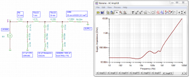
Attached plots show the supply impedance as seen from the LM3886 die looking out through its supply pin. The bypassing in the first picture is a 4.7 uF X7R ceramic capacitor. About 7 mm from the ceramic cap is a 22 uF Panasonic OSCON cap, then 30 mm further away a 1000 uF generic electrolytic can. From this point, the supply is connected through 20 cm (8") of AWG 20 (0.5 mm2) wire. The supply is assumed to be ideal (zero output impedance) as I'm only looking at the decoupling network. Any real supply will only degrade performance.
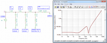
The second picture shows what would happen if we used two 4.7 uF ceramic caps in parallel. They are physically smaller than the electrolytic cap, so they can be placed closer - 3 mm apart.
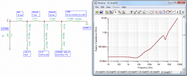
Finally, the last picture shows the supply impedance with the bypassing network recommended in the LM3886 data sheet (100 nF film cap, 10 uF tantalum, 1000 uF electrolytic can).
The parasitics for the various components, I obtained by measurements on an HP4194A impedance/gain-phase analyzer and/or from the manufacturer's specs.
As shown, the 4.7 uF ceramic (TDK P/N: FK20X7R1H475K) + 22 uF OSCON (Panasonic P/N: 35SEPF22M) + generic 1000 uF, 35 V electrolytic can provides much better performance than the network recommended in the data sheet. The ceramic cap is $0.86/EA @ QTY=1; the OSCON, $1.05/EA @ QTY = 1 according to Digikey.
Food for thought...
~Tom
The goal here is to have a low supply impedance, basically from DC to daylight. Now, at DC the resistance of PCB traces and wiring connecting the supply to the board sets the limit -- in my sim, the limit is 20 mOhm (20 cm of AWG 20 plus a couple of connectors or terminal blocks). At HF, the self-inductance of the IC package leads limit the impedance. The supply leads on the LM3886 are rather long. There is at least 7~8 mm exposed between the package an the board, and probably at least another 7~8 mm inside the package as well. So a little optimistically, I estimate 15 mm of lead length, resulting in 15 nH of inductance. This means the lowest possible supply impedance at 10 MHz seen by the LM3886 is 1 ohm.
Attached plots show the supply impedance as seen from the LM3886 die looking out through its supply pin. The bypassing in the first picture is a 4.7 uF X7R ceramic capacitor. About 7 mm from the ceramic cap is a 22 uF Panasonic OSCON cap, then 30 mm further away a 1000 uF generic electrolytic can. From this point, the supply is connected through 20 cm (8") of AWG 20 (0.5 mm2) wire. The supply is assumed to be ideal (zero output impedance) as I'm only looking at the decoupling network. Any real supply will only degrade performance.
The second picture shows what would happen if we used two 4.7 uF ceramic caps in parallel. They are physically smaller than the electrolytic cap, so they can be placed closer - 3 mm apart.
Finally, the last picture shows the supply impedance with the bypassing network recommended in the LM3886 data sheet (100 nF film cap, 10 uF tantalum, 1000 uF electrolytic can).
The parasitics for the various components, I obtained by measurements on an HP4194A impedance/gain-phase analyzer and/or from the manufacturer's specs.
As shown, the 4.7 uF ceramic (TDK P/N: FK20X7R1H475K) + 22 uF OSCON (Panasonic P/N: 35SEPF22M) + generic 1000 uF, 35 V electrolytic can provides much better performance than the network recommended in the data sheet. The ceramic cap is $0.86/EA @ QTY=1; the OSCON, $1.05/EA @ QTY = 1 according to Digikey.
Food for thought...
~Tom
Attachments
Last edited:
I am surprised at how similar are the ESL of all the different packages. A range from 3nH for the 100nF film to 8nH for the 1mF electrolytic.
Where does an 805, smd x7r come in comparison?
Where does an 805, smd x7r come in comparison?
I was a bit surprised to see the ESL be so similar between parts. For the low capacitances (<= 10 uF -- maybe <= 100 uF for the newer types), it's basically the lead inductance of 3~4 nH. The larger electrolytic cans show some additional ESL from their internal structure. The 'lytic I used was a good 10+ years old and there's been lots of improvements there, so you can probably get better performance with newer parts. Check their data sheets for the ESR and ESL.
The parasitic inductance of the SMD parts is a bit lower. Some of the low-inductance parts get down to 150 pH for 0201 types. The hand-solderable sizes are closer to 800 pH ~ 1 nH. If you're bypassing a big BGA package, where the supply lead is a solder ball with low inductance, you'll see a difference from using the low-inductance MLCCs. For the LM3886, it's mostly of academic interest because of the length of the LM3886 pins. Unless, you somehow manage to get the decoupling directly on the LM3886 pins up against the package itself.
Yaego's app note on ceramic replacements for tantalum caps is pretty good: http://www.yageo.com/exep/pages/download/literatures/an08436.pdf
~Tom
Last edited:
Hello Tom , which brand,which voltage ,which colour of 1mF have you measured 😀 ?
I have measured different capacitors of 1mF (panasonic,rubycon,samhwa,etc) and all have ESL about 30-50 nHenry .Meaning a resonant frequency about 5-10 khz .And also the ESR should decrease with the bigger capacitance .
I have measured different capacitors of 1mF (panasonic,rubycon,samhwa,etc) and all have ESL about 30-50 nHenry .Meaning a resonant frequency about 5-10 khz .And also the ESR should decrease with the bigger capacitance .
Last edited:
Hello Tom , which brand,which voltage ,which colour of 1mF have you measured 😀 ?
If I recall correctly, the 1000 uF, 35 V cap I used in the simulation was a Nichicon cap. Nothing fancy. It was black... 🙂
I have measured different capacitors of 1mF (panasonic,rubycon,samhwa,etc) and all have ESL about 30-50 nHenry .Meaning a resonant frequency about 5-10 khz .
30~50 nH sounds very high. Were you measuring at the ends of long leads by any chance? I mounted the capacitors in the test fixture much like I would mount them on a circuit board. The lead length was pretty short - maybe 1-2 mm.
And also the ESR should decrease with the bigger capacitance .
Unless you can back it up with data, I would be careful with blanket statements like that. A general purpose 1000 uF, 35 V electrolytic can may have an ESR of 50~100 mOhm whereas a 22 uF electrolytic capacitor, such as the OSCON caps, optimized for low ESR may be closer to 10~50 mOhm. It all depends on the plate/foil geometries, surface roughness, electrolytic chemistry, and such.
~Tom
So... I measured some more caps. This time some Panasonic ECE-series (pretty old stuff). There were no date codes on the caps - or if there was I wasn't able to interpret them. They're pretty nice 105 degree rated caps. They're probably 10 years old. Maybe 15... So about the same age as the LM3886... 🙂
220 uF, 50 V (10 mm diameter, 16 mm tall): ESR = 208 mOhm; ESL = 5.45 nH
330 uF, 50 V (10 mm diameter, 21 mm tall): ESR = 133 mOhm; ESL = 5.39 nH
470 uF, 50 V (13 mm diameter, 21 mm tall): ESR = 108 mOhm; ESL = 6.62 nH
~Tom
220 uF, 50 V (10 mm diameter, 16 mm tall): ESR = 208 mOhm; ESL = 5.45 nH
330 uF, 50 V (10 mm diameter, 21 mm tall): ESR = 133 mOhm; ESL = 5.39 nH
470 uF, 50 V (13 mm diameter, 21 mm tall): ESR = 108 mOhm; ESL = 6.62 nH
~Tom
I am surprised at how similar are the ESL of all the different packages. A range from 3nH for the 100nF film to 8nH for the 1mF electrolytic.
Where does an 805, smd x7r come in comparison?
All leaded film caps are inductors at relatively low frequencies and useless for bypassing. They're fine for making filters, for example, but not for bypassing. The ESL is just too high.
In a well-built capacitor, ESL is determined mostly by geometry, that's the area of the loop the current will have to travel through. So, on a leaded part, if the leads have equal spacing, and the butt of the capacitor rests on the PCB, there isn't much that changes between different types of caps, the current goes in through one lead, through the plates, out through the other lead... depending on the construction the loop area may change a bit but not an order of magnitude.
The only thing that has low inductance is SMD ceramic caps. That is simply due to the fact that they are small, low-profile, and hug the PCB closely. The smaller the lower the ESL. Mounting inductance is higher than the actual ESL of the parts, and also shrinks when the parts are smaller.
Spreading values (like 1u, 100n, 10n) so that the smaller cap "handles the higher frequencies" is an urban legend that dates back to the time when small package capacitors were only available in small capacitance values. Since the inductance depends only on the capacitor physical size and not the actual value, a 1nF and 10uF capacitor of the same size (say, 0805) have the same HF behaviour.
But... if you don'y have close coupled ground/power planes, SMD ceramic caps are a bit overkill... if you use PCB traces the inductance will be high anyway.
ESR is your friend. When you parallel two capacitors you create a LC resonant circuit. This needs a resistor to damp it. If is is underdamped it will resonate and the impedance of your power supply will have a nasty peak. This is bad. So it's a subtle play between R, L, and C. If you decrease L, by using low-inductance caps and mounting, then you can afford to decrease R and still have good damping.
At a specific value of L, you have a choice. You can use a very low ESR cap, like a ceramic or a polymer, but the low ESR will only lower the supply impedance in a small frequency range, which is the tip of the "V" in the capacitor impedance curve. Outside of this range, the low ESR makes things more difficult by increasing undamped resonances with the other paralleled caps. So if you want really low-ESR (like a few mOhms) you will need lots of polymer caps of various values and increasingly smaller packages. A bit more ESR simplifies things and needs a lot less caps.
This is why Sanyo sells OSCONs with various ESR ranges, from a few mOhms to about 50 mOhms. OSCONs are nice not because they have low ESR, but because they have just the amount of it that you need, along with low ESL.
Last edited:
As shown, the 4.7 uF ceramic (TDK P/N: FK20X7R1H475K)...
The DS I looked at for this part from Mouser didn't show the characteristic loss of capacitance with DC bias. This should really be taken into account when simulating. Sometimes the ESR is affected by bias too.
Over on TDK's website their SMT ceramics can be searched by capacitance under a specific DC bias, a really cool feature.
Search by Characteristic | Multilayer Ceramic Chip Capacitors | TDK GLOBAL
The largest package SMT ceramics are least affected by DC bias. A 2220 case 4.7uF, 50V X7R shows 4.06uF @ 35V. Larger packages though have poorer ESR than smaller, so oftentimes its better to parallel smaller case sized ones (which are significantly cheaper to boot).
All leaded film caps are inductors at relatively low frequencies and useless for bypassing. They're fine for making filters, for example, but not for bypassing. The ESL is just too high.
Again, I'd be a bit leery of blanket statements here... I measured a 100 nF film cap (polyester, I think). 3 nH. Same as a 47 nF ceramic cap. The ESL depends on the geometry of the cap. MLCCs have low ESL because of the many layers forming many capacitors in parallel. The stackfoil caps of yesteryear used the same principle, just with polyester film rather than ceramics.
I have also measured some leaded Solen brand polypropylene film capacitors. 47 uF, 630 V. 5 mOhm. Yes. Five milliohm.
In a well-built capacitor, ESL is determined mostly by geometry, that's the area of the loop the current will have to travel through.
I would say, the ESL is all about the geometry. Not so much about the dielectric.
So, on a leaded part, if the leads have equal spacing, and the butt of the capacitor rests on the PCB, there isn't much that changes between different types of caps[...]
The only thing that has low inductance is SMD ceramic caps.
Agree 100 %.
Spreading values (like 1u, 100n, 10n) so that the smaller cap "handles the higher frequencies" is an urban legend that dates back to the time when small package capacitors were only available in small capacitance values.
Actually, spreading out the capacitances like you describe is a good strategy if the IC lead inductance is lower than the ESL of the bypass caps. This is often the case for BGAs where multiple balls are used in parallel for low inductance. However, in cases where the lead inductance dominates - such as with the LM3886 - a better strategy is to get as much energy storage as close to the IC pin as possible.
ESR is your friend.
Sometimes, yes...
This is why Sanyo sells OSCONs with various ESR ranges, from a few mOhms to about 50 mOhms. OSCONs are nice not because they have low ESR, but because they have just the amount of it that you need, along with low ESL.
I suspect those are intended for use with switching regulators that rely on the ESR for stability. That doesn't prevent us from using them as decoupling caps, though.
The DS I looked at for this part from Mouser didn't show the characteristic loss of capacitance with DC bias. This should really be taken into account when simulating. Sometimes the ESR is affected by bias too.
The largest package SMT ceramics are least affected by DC bias. A 2220 case 4.7uF, 50V X7R shows 4.06uF @ 35V.
Very true. Though, the change from 4.7 uF to 4.1 uF is not enough to make me shake in my pants.
Definitely spend the money for a good X5R or X7R cap. If you go with a cheapie Y5V, you'll only get about 25 % of the rated cap at 50 % of the rated voltage. The tempco is pretty horrid as well.
~Tom
Murata provides a great application for there Ceramic caps...
Download | SimSurfing (DL) | Murata Manufacturing Co., Ltd.
Download | SimSurfing (DL) | Murata Manufacturing Co., Ltd.
Kemet has a good one as well. Sadly, however, it's Windoze only...
Kemet Spice & FIT
They also have a cool web-based electrolytic capacitor life calculator. Turns out if you run one of their 10000 uF, 50 V, 105 degree rated caps at 24 V, 1 A ripple (120 Hz), 50 degrees ambient temp it'll last 22 years of continuous use (versus 10k hours = 1.1 years at the full rated specs).
~Tom
Thanks - I don't know about the Kemet App. - but I don't encounter Kemet parts here in Europe very often, but I guess the lifetime calculator applies pretty much to any equivalently rated parts (Life / Temp).
If I recall correctly, the 1000 uF, 35 V cap I used in the simulation was a Nichicon cap. Nothing fancy. It was black... 🙂
30~50 nH sounds very high. Were you measuring at the ends of long leads by any chance? I mounted the capacitors in the test fixture much like I would mount them on a circuit board. The lead length was pretty short - maybe 1-2 mm.
Unless you can back it up with data, I would be careful with blanket statements like that. A general purpose 1000 uF, 35 V electrolytic can may have an ESR of 50~100 mOhm whereas a 22 uF electrolytic capacitor, such as the OSCON caps, optimized for low ESR may be closer to 10~50 mOhm. It all depends on the plate/foil geometries, surface roughness, electrolytic chemistry, and such.
~Tom
Tom ,
It is important at which freq you measure the ESR and ESL .
From "ESR Frequency Characteristics" in this link http://www.cde.com/catalogs/AEappGUIDE.pdf and also at pg 27 here http://www.usna.edu/EE/ee320/Supplements/dcdc2_capacitors.pdf
you can see clearly that ESR varies inverse proportional with the capacitor .
Also It would be good if you can measure the resonant frequency in your test .It would be a good indicator to see if it fits the esl + the cap value in the resonant freq equation 1/(2*pi*sqrt(C*L)).
And yes I have measured at 1 cm from the case.
Usual my caps about 10mF has a resonant Freq about 5-10 Khz (rubycon) low impedance .
Take care at the measurement system wire also , approaching the wires or not can decrease /increase the inductance after the calibration step .
Last edited:
It is important at which freq you measure the ESR and ESL .
As mentioned in the my first post, I measured the impedance of the capacitor using an HP4194A and used its built-in equivalent circuit calculator to find the ESR and ESL. The 4194A measures magnitude and phase of the impedance, finds the capacitive and inductive slopes, and calculates the capacitance and ESL from there. The ESR is found from the impedance at resonance. For a wide-band circuit model this is completely valid.
An externally hosted image should be here but it was not working when we last tested it.
And yes I have measured at 1 cm from the case.
That adds at least 20 nH to the measured inductance.
Usual my caps about 10mF has a resonant Freq about 5-10 Khz (rubycon) low impedance .
10000 uF, f0 = 10 kHz would mean the inductance is 25.3 nH. That's 20 nH of lead inductance due to your excessively long leads and 5.3 nH for the part itself which is in line with what I measure. I suggest remeasuring with as short lead length as possible - certainly no longer than 1 mm for exact measurements.
Take care at the measurement system wire also , approaching the wires or not can decrease /increase the inductance after the calibration step .
In my setup, there is no wire to take care of. I use an HP 16047E test fixture that allows me to clamp the cap in place with minimum lead length.
An externally hosted image should be here but it was not working when we last tested it.
~Tom
I stumbled on this sometime back when doing some sims of the speaker return location. A bit scary is that the resonance is in the audio band. The largest cap seemed to cause most of the resonance. Lower capacitance and or ESR just made things worst. I used a Nichicon 1500uF, 100uF and a TDK 1uF X7R.


Maybe of some help here.
Maybe of some help here.
Last edited:
Some measurements you may find interesting :
http://www.diyaudio.com/forums/solid-state/253390-experimentations-regulators-2.html#post3872912
http://www.diyaudio.com/forums/solid-state/253390-experimentations-regulators-2.html#post3872912
Mark,I stumbled on this sometime back when doing some sims of the speaker return location. A bit scary is that the resonance is in the audio band. The largest cap seemed to cause most of the resonance. Lower capacitance and or ESR just made things worst. I used a Nichicon 1500uF, 100uF and a TDK 1uF X7R.
View attachment 408402
Maybe of some help here.
all three capacitors are shown as "perfect".
How much does the peaking change when you add a little ESL and a little ESR to each of the capacitors?
The inductances are way too large and it needs a snubber at the AC input (and maybe some extra ESR...)
I measured the following contraption with the VNA :
- big fat noname 10000µF snap-in
- 10cm zipcord
- ZL 470u + 10u ceramic
No resonance problems... there is enough ESR in the caps to damp it. With ultra-low ESR caps, problems may occur. The whole contraption (without the ceramic) has roughly the same performance as the snap-in alone, the local cap serves only to restore the HF performance after it being wasted by the long wire... Note that the two local caps were properly paralleled (planes not traces !...)
- Home
- Amplifiers
- Chip Amps
- LM3886 Bypassing Revisited (applies to other chip amps as well)