Mark,
all three capacitors are shown as "perfect".
How much does the peaking change when you add a little ESL and a little ESR to each of the capacitors?
The parasitics don't show in the schematic. I loaded the parts from the library that comes with LTspice.
Since you model high inductance, this means traces, you need to add their ESR. If you use planes, you have much less inductance, thus much less problems...
I think the largest resonance comes from the supply inductance, did you add some ESR in the sine source at the left ?
I think the largest resonance comes from the supply inductance, did you add some ESR in the sine source at the left ?
Just add the capacitor parasitics by adding extra components.
Each capacitor will have some ESL and some ESR.
Add those into the schematic.
Each capacitor will have some ESL and some ESR.
Add those into the schematic.
Nichicon UPL1H152MRH
C=1500uF
U=50V
I=2.41A
ESR=0.026
ESL=0
Hi Andrew,
this is the cap I used. All these values are included in the simulation, Not all the values can be seen in the schematic. Doing it this way its easy changing caps (including parasitics). Its also possible to add your own caps to the list.
I didn't try to optimise anything. It would have been pointless posting something that didn't look bad.
The peak on your curve corresponds to the LC resonance of the wire inductance (800nH) and the big capacitor.
You really need to add the source's ESR...
You really need to add the source's ESR...
Just add the capacitor parasitics by adding extra components.
Each capacitor will have some ESL and some ESR.
Add those into the schematic.
Andrew, in most simulators, it is possible to include the ESR and ESL with the capacitor directly as parameters to the capacitor. In those cases, the ESR and ESL will not always be shown explicitly on the schematic but are still modeled. Most schematic editors (including LTspice as I recall) offer to print the parasitics on the schematic by clicking a checkbox in the capacitor symbol/model setup, and it's generally good form to do this when including the parasitics in the model.
~Tom
It depends if the diodes are on or off...
90% of the time the diodes are waiting for the next tsunami to arrive.
Andrew, in most simulators, it is possible to include the ESR and ESL with the capacitor directly as parameters to the capacitor. In those cases, the ESR and ESL will not always be shown explicitly on the schematic but are still modeled. Most schematic editors (including LTspice as I recall) offer to print the parasitics on the schematic by clicking a checkbox in the capacitor symbol/model setup, and it's generally good form to do this when including the parasitics in the model.
~Tom
Before posting the schematic, I looked at both methods of placing the parasitics on the schematic, couldn't get it to work.
90% of the time the diodes are waiting for the next tsunami to arrive.
Yep, you have to handle both cases.
Diodes off, model them with their parasitic capacitance. Diodes on, model with a resistor. Add transformer inductance and resistance.
It is much simpler to just power up the device, and examine the voltage on the transformer secondary with a scope through a highpass filter (like 10nF+1kOhm to ground). This will remove the 50 Hz and the underdamped oscillations can be observed. Then the snubber across the transformer secondary can be adjusted (a 100R pot + 100nF capacitor). Once the right value of the pot is found, it can be replaced with a fixed resistor.
The Generic cap used by tomchr (1000uF/52mR) in the first post works much better than a low ESR cap as far as resonance.
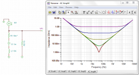
Depends on your criteria for "work better". Attached is a graph of the impedance of a cap as function of frequency and ESR. The lower ESR, clearly provides a "better cap" - i.e. lower impedance. However, the lower ESR also increases the Q of the resonant circuit.
A Q of 0.5 provides the flattest time domain response. I'm not sure that's what you actually want, but a Q in the range of 0.5~1 is probably a reasonable FOM.
Q = XL/R --> XL/2 < R < XL, where XL is the reactance of the ESL at the resonance frequency f0: 2pi*f0*L.
~Tom
A Q of 0.5 provides the flattest time domain response. I'm not sure that's what you actually want, but a Q in the range of 0.5~1 is probably a reasonable FOM.
Q = XL/R --> XL/2 < R < XL, where XL is the reactance of the ESL at the resonance frequency f0: 2pi*f0*L.
~Tom
Attachments
There were a few comments about resonance frequency and oscillations related to low ESR and I remembered a few sims I had done when testing speaker return locations which showed a resonance. Seemed relevant at the time.
Here are 2 more.


Here are 2 more.
Q only matters if you have an actual closed resonant circuit 😉
In practice this happens when capacitors are paralleled, either explicitly (decoupling/bypass) or implicitly (real capacitor + hidden capacitor, maybe a diode)
Trace, wire, and mounting inductance is likely to be a large part, or much larger than the actual capacitor ESL
A low-ESR capacitor is a better cap ... until it is paralleled with other caps... which creates an antiresonance peak. Lower ESR, higher ESL, and higher distance between capacitor values give larger peaks (higher Q).
So if you choose to target a specific impedance (or simply wish to avoid nasty resonances), choosing a too low target impedance will need lots of caps, at which point the contraption will get larger, connection inductance will matter much more, and you'll need power and ground planes, etc.
That's why "controlled ESR" ceramics start to appear, with ESR in the 10-100 mOhm range, and specified with a reasonable precision. This way they can be paralleled with much less problems. Unfortunately this is a new product, so for the moment they are prohibitively expensive...
Some of the OSCON type caps are available in a controlled ESR option as well.
The anti-resonant peak. Yeah that makes sense. If each cap create a deep notch with steep slopes, you need many caps close together to smooth out the resulting impedance curve.
You know... You think you're designing an amplifier. But if it doesn't turn into a power supply project, then you're really doing it wrong... 🙂
~Tom
You know... You think you're designing an amplifier. But if it doesn't turn into a power supply project, then you're really doing it wrong... 🙂
😀
Actually I don't think it is that important, I mean if the output is an emitter follower, it doesn't really care if the supply impedance is 0.001 ohm or 0.1 ohm... as long as it isn't too much inductive...
For example the best LDO that I measured in the other topic (the one that has milliohm output impedance out to hundreds of kHz) ... with a 10 ohm resistor in its power supply, it doesn't really care as long as it has its local ceramic at the input for low inductance, and enough voltage margin to work...
In a power amp I think that giving clean power to the small signal stages should be more important than having ultra-low impedance stiff rails for the power stage... Just a hunch.
For your LM3886 though, it doesn't have separate pins for supplying the small signal stages and the power stages... and the power stage will draw class-B half wave current... so low-impedance may be more important.
For a discrete design where loop gain is relatively limited, you should see a benefit from using a regulated supply on the input and VAS stages. The output stage supply would matter less and any disturbance introduced there attenuated by the loop gain.
The LM3886 is a different animal. First off, the loop gain is much higher than you'd see in a typical discrete design. Secondly, it uses current mirrors everywhere. This means most of the active circuitry is isolated from the supplies by the transistors used in the mirrors. This means the main mechanism for introducing an error through the supply will be by the limited Early voltage of the mirror transistors. In a MOS mirror, you see the channel length modulation come into play in those types of situations. Those effects are tiny compared to what you'd see in a discrete amp. That combined with the higher loop gain explains the high PSRR of chip amps like the LM3886.
I'm not knocking discrete designs. But it's rather hard to beat the performance of an IC with discretes... I've tried...
~Tom
- Home
- Amplifiers
- Chip Amps
- LM3886 Bypassing Revisited (applies to other chip amps as well)