Preamp rebuild help . $$$$$

Hello , not sure if this is the spot to post or even the forum/wensite but here goes..
I have had nothing but great info and knowledge passed on to me from here. I was now wonedering if you could pass some more ?

Sooo if I were to take some detailed nudes of my preamp (magus mfa ) and post them with a parts and labour list buy of refresh and upgrade that are recomemded buy the creator of my pre (so tested and true ) would any one here be interested in helping me A-order the stuff to do it plus some new potentiometers that arent on the list B- take a screen shot of my pre and PS and circle what goes where , then send it back . I know. I know it should be easy .Im pretty good but have only did some small cap replacements What with all thats going on i didnt plan on doing it my self but...


I dont want this for free . Ill etransfer 1/2 up front . This kinda thing for the right person is 20 min . Please let me know your thoughts . Thanks every one
Ken

Audax, Vifa, Seas, Peerless, Polydax, AR, NHT drivers

Hey, Guys,

Doing a little closet cleaning and have a bunch of drivers to sell off:

4x AR 1210064-08 1" dome

1x AR 1-210155-2 5.25"

Pr. Audax AT170ZGP W08ZGP 6.5" treated paper, rubber surround

Pr. Audax HT110G0 5" treated paper, rubber

1x Audax TW037Y0 dome mid

1x NHT 1-11-043-1 6.5"

1x NHT 11-001-03 4.5"

Pr. NHT 1" dome, shielded

Pr. Nokia 4" paper, shielded

Pr. Peerless 1" domes, shielded

Pr. 1" domes "Star Trek / Ouija board" faceplate

1x Polydax 4" paper, shielded

Pr. Polydax HIF17JVX2CA12 6.5"

Pr. Seas D20TD-05 3/4" domes

Pr. Tonegen 8", poly, rubber

4x Tonegen 4", treated paper, in enclosures

Pr. Tonegen .75" dome

Pr. Vifa 6.5" molded plastic frames

Pr. Vifa 6.5" molded plastic frames, bucking magnets

Pr. Vifa 6.5" molded plastic frames, shield cans

Pr. Vifa TC26SF05-06 1" dome

Pr. Vifa 3.5" poly, rubber

No- name 12", heavy steel frame, bunch of other stuff, just tired of writing. Might be a little off on some of the details, but you get the gist. I'd like to get $200 for the lot. Available for pickup in Richmond, CA most weekends. For $100 more, I'll through in a bunch of 6.5" and 8" woofers.

Anyone want to pick them up?

distance from power supply and amp module

hey all,


been searching for a few days on this topic, nothing totally dedicated that i can find so apologies if this has been discussed else where at length


have (2) L20.5 amp modules, and (2) SMPS to power them. is there a required distance they should be away from one another in the same enclosure? the amp modules will be mounted vertically on the enclosure's side heat sinks, while the SMPS will be mounted horizontally (so perpendicular to one another) and the space is somewhat tight, probably 2 or so inches from one another. will this be problematic?

WIMA capacitors for audio

In "6 - 24 crossover" thread there was some time ago a short discussion about the quality of WIMA capacitors. Also a little about the "mysterious" about the "Black box WIMA's". I decided to ask about them and also which WIMA type to select today for audio. After a couple of mails and some waiting I got this information. It is information only.....I don't sell WIMA's 🙂

********************
The BlackBox was a special edition that we developed in early 2000.

With this special edition, the goal was not to be pricely competitive against our competitors. The goal was to deliver the best sound experience.

After several research and testing, we concluded that the use of a thicker dielectric drastically minimizes vibrations inside the capacitor, which has a positive effect on the sound quality.

We used a polypropylene dielectric with a polyester foil metallized with aluminum. This dielectric was thicker and as you can see very clearly the BlackBox edition has physically larger dimensions than the standard capacitors.

When the dielectric is thicker and you need more raw material for the caps and potting, the capacitors have a higher manufacturing cost and value.

The BlackBox standard alternative today will be direction MKP10. However, it is very important if you want extreme sound quality and if there is enough space available, that you consider a higher dielectric strength and higher nominal voltage due to the film thickness: The higher the nominal voltage, the thicker the foil.

What was then a BlackBox 250 VDC ... today should be something like the MKP10 series in 400 VDC, because of the thicker foil.

Example:

MKP 10, 400 VDC, 0.33 µF 20% = BlackBox 250 VDC, 0.33 µF 20%.

Nevertheless, the 250 VDC´s capacitors are also very optimal and beloved for sound engineering. This is because of the high quality of WIMA capacitors.

Most of our audio customers today also prefer a capacitor with a lower tolerance: 5%. Somehow this lower tolerance also has a positive effect on the quality of the sound.

I hope I could help you guys a bit further.

Stay safe and healthy.

***********************

Arcam FMJ MS250 issues

Only just picked this up cheap.


It gets stuck at start up saying "initialising" and that is it, hard drive sound happens and CD drive, but does nothing else at all.


It has a ram module in it, could that be bad? Or hard drive? I took the HD out but it was still stuck on start up, tis driving me mad!!! Does anyone know what type of RAM it uses?


Any help would be appreciated

MMTMM Center Channel, would like advice

This is my first start to finish speaker build and I have some questions I was hoping you guys could answer. I have built one pair of speakers before, a DIYSoundGroup pair of Apollo 7 TMs. I was really happy with them as a stereo system and now I want to put together a 3.1 system. I am constrained a little bit with height, as TV mount height limits me to 5” of clearance.

The 5” clearance is where the need to build comes into play. I was shopping around for center channel, but i wasn’t excited about the ones I found that would fit.

At first I was thinking of a MTM in a vented box, but then I got to thinking about a MMTMM in a 2.5 way configuration. I’ve been toiling around with WinISD and XSim, but am not exactly 100% confident about what I’m doing.

For the box I plan to use 1/2" MDF instead of the usual 3/4, in order to save space. I've played around with a small one and a larger one, but in it's current design I am thinking of two separate chambers instead of one big one. Each having a vent off to the side. Does this serve an advantage over one large box? With the current tuning I should get an F3 of 77.5, which should be fine.

For driver selection, I figured it would make sense to use a tweeter that is the same as my other speakers to match, the Wavecor TW030WA11. It happens that the Wavecor makes a pretty good looking driver that fits the bill. I've also looked at some Daytons, a Tang and one from Scan Speak.

Tweeter: TW030WA11

Wavecor TW030WA11 30mm Semi Horn Loaded Textile Dome Tweeter with Rear Chamber 4 Ohm


Woofer: WF120BD03
Wavecor WF120BD03 4-3/4" Balanced Drive Paper Cone Mid-Woofer 4 Ohm


I think I should keep it 4 ohm to match my Apollo MT's. Does this make sense?

Do I base my voltage on Denon’s states specs of 75w into 8 ohms stereo? Does a home theater receiver’s power change when driving 2, 3, and 5 channels?

How much should I be concerned with baffle step here?

Given that this is a MMTMM center, do I need to only look at "Midrange" speakers vs Woofers? I understand that these differ, but for this application which way should I lean?


After reading a good amount of reading, I'm looking at 2.5 way instead of a 2 way. It seems a bit more complicated, but not too crazy. It looks like if I wire the mids in parallel-series I can keep the ohms at 4.


Thanks in advance for any advice! This is still the first real draft and some of the dimensions are still in play. Also, I'm a noob here obviously, and there will probably be some very obviously problems here that I am not seeing. Cheers!

Attachments

  • MMTM Wavecor.png
    MMTM Wavecor.png
    16.7 KB · Views: 123
  • MMTM Wavecor3.png
    MMTM Wavecor3.png
    27.3 KB · Views: 117
  • MMTM Wavecor2.png
    MMTM Wavecor2.png
    28.3 KB · Views: 121

Help needed to Fix or Repurpose old Speakers

Hello,

Some time ago I wanted to rebuild a pair of old speakers, and I got a lot of great advice, but I just did not have time to get into it until now. I have already been given many tips about kits being better for newbies to learn, I have embraced this and I already have a couple in mind for another future build 😀

So I have changed my mind on what type of approach I want to try for these old speakers, so instead of “reviving” that old thread I figured I rather make a new one because I would like instead some feedback, tips and opinions on weather to fix or repurpose these speakers which sound quite good and I would very much appreciate your input to weigh my options!

Disclaimer: I am still relatively new in this realm so for the moment I am not savvy enough to be up to the task of designing and making a crossover from scratch and creating a whole speaker from scratch, nor heavily investing in the repair/repurpose. This is more of a simplified rescue to get into experimenting with speakers and box building. So cost and simplicity are the most important parameters for me for this one 🙂

Speakers (pictures attached) : they are an old pair of 3-way Sanyo SS-60 speakers.
I don’t have any detailed specs to them except for the ones below and on the speaker themselves (I know it's nowhere near enough info for complex approached but it is what I have found for these oldies):
Power-> 60/120watt
Freq. Resp.-> 30-20000Hz (cant find +-db anywhere)
Impedance-> 8ohm
Highs-> 5cm
Mids-> 6cm
Woofer-> 18cm

“Plan” A - Fixing: Just redo the box respecting internal dimensions and reusing original vent for the sake of the woofer (I don’t yet want to get too deep into measuring parameters, this will be something for another project), keeping electronic components as is as much as possible. I will check these days if the smaller speakers are worth fixing (small tear on the surrounds and sometimes a high and a mid wont sound). If the smaller speakers don’t work then I won't try this approach as I assume I will have to start matching speakers and designing Crossover, etc.

For this Plan-A my main doubt is regarding the crossover. These 3-ways don’t have a “normal” crossover (at least not like the ones I have seen online on a nice neat plate). It seems that there are resistors, capacitors, etc, stuck directly to the wiring that is connected between speakers. (pictures attached of the back part of each speaker)
-Is this like an “old” way of doing it?
-And would it be a good idea to simply replace all of these “crossover” components for new ones and re-hook it up following that same “old” way? Or is there a better way to rebuild the crossover following the “old” way (like using the same type of components on a plate)? Any tips/corrections/resources to how to do so are very welcome.

“Plan” B - Repurpose: Assuming all speakers work.. Dismantle the speakers, and make different “types” of speakers for a small DIY 5.1 setup (actually “4.1” since I don’t have a center speaker yet). So in short I was thinking of making 2 subs out of the 2 woofers by making 2 boxes and adding amps to each. Then take the high/mids speakers and put them in small boxes to make the satellite/rear speakers of the "4.1".
(They would be used with an old Yamaha RX-V430RDS, which has a fixed cutoff at 90Hz for the sub, and has 1 sub pre-out.)

These ported woofers seem to have quite a good lower end judging mainly by how deep and good they sound with various types of sub-heavy music hence why I wanted to attempt this. My reasoning (if any lol) with the “4.1” set up is to mainly skip the tampering with designing a whole new crossover for now which is a bit overwhelming for me at the moment as I am starting my learning with that.. so..

a) I am assuming that small rear speakers don’t have/need crossovers, and to be honest it has been challenging to google if I need a crossover for small rear speakers for surround sound.. from what I have read it seems that unless I want a high end surround speaker I don’t really need a crossover for the surrounds.. am I wrong?

b) Also I am assuming that adding an amp to the woofer to make an active sub seems** like a simpler undertaking compared to the crossover.. am I also wrong?

c) So for the DIY sub, is it as simple as redoing the current box (keeping internal volume and port) and adding an amp matching the power rating and ohms of the woofer? Is this ok or does the box design game change completely once it is a powered woofer? If so, I would appreciate tips and some good resources for me to read up on.

d) For the sub amps, would an external amp to which I would connect both woofers be a better option/have an advantage as opposed to separate plate amps? Would having an external amp save me the redesign of a box and allow me to just recreate the current box and connect? Again, any tips & resources on how to match either the internal or external amp is appreciated.

As I mentioned this is a newbie experiment/rescue, so measuring and interpreting parameters and crossover designing is for now a bit out of my league (at least I think so, if some things are doable please correct and teach me) 😉

I really appreciate any advice, recommendations and critiques to both “plans” so I can weigh my options

Thanks!!

Attachments

  • Sanyo2.jpeg
    Sanyo2.jpeg
    93.1 KB · Views: 397
  • Sanyo1.jpeg
    Sanyo1.jpeg
    262.4 KB · Views: 379
  • 1-Woofer-model.jpeg
    1-Woofer-model.jpeg
    161.7 KB · Views: 394
  • 2-Midrange-model.jpeg
    2-Midrange-model.jpeg
    115.4 KB · Views: 386
  • 3-Tweeter-model.jpeg
    3-Tweeter-model.jpeg
    128.9 KB · Views: 387

Repurposed crossover for sub wiring question

Hello,

This is my first post here. Hopefully, I've posted in the correct forum.


I'm salvaging a polk subwoofer with a blown amp by trying to convert it to a passive sub.

I have a crossover out of a Bose Acoustimass 5 series ii subwoofer.

The crossover has inputs and outputs for both right and left since the bose sub had two drivers.

The Polk sub has one driver.

Should I connect both the right and left outputs of the crossover to the one driver?

Thank you for looking!

Attachments

  • IMG_9146.JPG
    IMG_9146.JPG
    800.1 KB · Views: 118

Choosing A 15" Woofer

I'm looking for a 15" woofer for a new pair of speakers. I want an F3 of 30 Hz (built), better yet, 25 Hz, "probably" in a vented box, but sealed is fine, too. Crossover at about 150 Hz or less to the upper bass driver. I would like to have a box of less than or equal to about eight cubic feet (<= 8 C.F.) (about 2' x 2' x2'). One woofer left and one right - not a single, and not "multiple".

I'm aware of JBL 2226 - doesn't go low enough. Aware of Dayton 15" - not available. Eminence - I haven't seen "the one".

Anyone have another idea?

To review:

15", F3 at <= 30 Hz (built), ~ max cabinet 8 C.F.

Thank you!

7 channel DIY surround amplifier options

Hi,

I'm new here, but the moment I saw the baking tray amplifier on the gallery I knew I was in the right place.

I'm putting together a home cinema system and fancy building the power amplifier myself. I've done plenty of electronics projects in the past and have been looking at my options.

The two basic ideas I have are:

1. Buy 7 replica Quad 405 boards for about $30 each which are about 100W RMS into 4 ohms.

or

2. Buy 7 class-D amps aiming for about 300W RMS each.

As a person who has studied power electronics I understand the technical differences. I also don't want to open up a long debate about how good different class D amps sound.

Given that the Quad circuit is well and truly tried and tested and can be had for less than $40, is there any real point in going down the class-D route?

FYI the surround system will be based on six ATCs SCM7s and one ATC C1CA, probably driven by an Arcam AVR of some sort.

Thanks in advance for your advice.

Rear loaded horn design like AER Aerofon

Hi guys

I have been playing with full range drivers for a while. My current favorite is my Fostex FE126 Planet10 modified unit, in a double folded horn. I also have a pair of Fostex 8" Fe 206 that i have tried in various configs, but have not been totally satisfied. I have been thinking of using them in something like the "Kleinhorn" or "Sato" for the longest time, but am put off by their massive footprint, until I came across the AER Aerofon. Much smaller footprint, and similar concept. I see that they spec theirs down to 35Hz. I do understand that this is driver dependant, but would like to try this design for my Fostex 8". Anyone have any plans for a horn of this type and size?

Kevin Gilmore Dyahi

Update: “Sold” to the lowest bidders


Found these in the bottom of a box, they were given to me back in 2005 and have traveled the world as I moved around (not that that adds any value but just shows I should have admitted I had no interest in them years prior)

Free to good or bad home with preference going to the easiest shipping (that means USA folks, but if no takers I’ll upgrade to an international stamp and hope for the best). If you care about them securely arriving at least show me you have or tell me you will make a donation to the forum and I’ll pay for proper shipping.

PM or post up to you, and please tell me if you want all four as most would only ever use two of them so I will assume you want two in the absence of clarification.

P.S. This design uses some unobtainium critters, please don’t ask me for further details as it’s all at your fingertips.

Attachments

  • 9E00EBCD-DDFB-4D54-86F4-C2CA617CA632.jpeg
    9E00EBCD-DDFB-4D54-86F4-C2CA617CA632.jpeg
    159.3 KB · Views: 237

Audionote copper mylar in oil failed

Hi guys..

I just want to share my experience with Audionote copper mylar in oil caps.

I built 300B SE amp base on Audionote Quest but modificated to stereo amp instead of monoblok amp. I used Audionote caps 0.33 uF/630v copper mylar in oil (copper tube, black label not white and diameter bigger than current Audionote caps). I bought 1 pair from Partsconnexion Canada (they are a nice seller doh) about 1 years ago and just 6 months ago I finished the project and started to fire up the amp and sounds very lovely.

2 days ago I turned the amp and playing some vocal music, everything seems going ok until 2 hours during playing some slow music sudently I heard very bad distortion on my left loudspeaker and the volume seems decrease. I smelled bit burnt odour near the cathode resistor (it's very hot on that resistor). I hurry up turn off the amp, get my multimeter and checked everything until I found that the Audionote coupling cap was shorted and pass through 271vDC!!

Maybe you guys ever have experienced fail caps as I did? I've sent complaint to Audionote contact via email and haven't any reply until 2 days maybe they too busy 🙁
I questioned them about the quality control and cap durability or maybe I just unlucky hehe.....I never experience any problem with other cap I use until now (I also use Jensen copper in oil, Mundorf Silver Oil, Supreme, Dynamicaps, Jantzen Silver, etc)

For now I doubt to use Audionote cap again, maybe I will try Jensen paper tube instead buy again AN caps

cheers....
Erik

On-Off Thumps

I've built several kind of amps, from fully symmetrical design to single differential design. All have turn on and turn off thump.
Searching here, the most encouraged cure is to use output relays.
But some good commercial amps do not have these thumps, although they do not use delay relay at all.
1. What is the mechanism of this Thump generation?
2. Is there any trick if we design an amp so it will not have thump?

Analogue to digital for correction

I am considering the idea of using digital correction for room and speaker correction.
However i use vinyl as a source and a tube amplifier (amongst other things)
Is there a high quality and inexpensive way to do this or is this simply incompatible.
I am not really sure where the thread belongs but would be very interested to have some input.
Thanks
Mike

Method to protect a MOS-FET->BIPOLAR 200V powered amplifier during tests

Helo,guys !

Do anybody has different method to protect during trial tests a 200V powered amplifier - repaired on left channel ?

I mean everything seems fine on ± 20V, ± 30V etc. .... but on ±100V instead of burning 5A fuses (normally should be 10A fuses) , burned again final and prefinal transistors.

Idle current is normal (like in non-burned right channel) , all voltages seems the same (like in non-burned right channel), no DC on output.
I've marked on diagram "burned 1" and "burned 2" meaning "burned 1" = what found already burned when amplifier was received, "burned 2" = what keep on burning during trial tests.

On trial test I've had weaker final transistors (2SC5198 SI-N 140V 10A 100W 30MHZ - TO3PN / 2SA1941 SI-P 140V 10A 100W 30MHZ - TO3PN instead of : MJL3281A NPN TO-264 260 V, 15 A, 200 W / MJL1302A PNP TO-264 200 V, 15 A, 200 W and also Q409 = MJE350 SI-P 300V 0.5A 20W was substituted by weaker B861 PNP -200 V -2 A max 30W) - and ONLY 2 of final transistors WERE USED , a PNP and a NPN - but based on datasheet should be working , at least for a while on ± 100V power supply.

Reason for burned2 is that potentiometers were so old that became noisy and during volume up it was a strong noise from potentiometer going to speaker - "overload" the stage - and after that R428 smoked by Q410,Q411 shorted etc .

Regarding fuses: Due amplifier is rated 2 x 600W I thing fuses should be around 6A not 10A as in diagram, no matter one MJL is max 15A.
One SC transistor is rated 10A but during trials both of them shorted altough 5A fuses not burned (to protect anything).

Burned2: Both 2SC5198 and 2SA1941 shorted between B-C not E-C
Burned2: IRF 630 shorted between G-D (10 ohms)
Burned2: IRF 9630 shorted between G-S (0 ohms)
Strange is R407 was burned1 altough Q401 ok.

Also, I think on 100V thermal heatsinks transistor silicon pads could be affected as electrical insulators.

My method was:
1. Tested idle current, DC current on ± 20V with 48V/ 20W lamps instead of fuses - ok
2. Tested idle current, DC current on ± 80V with 48V/ 20W lamps instead of fuses - ok
3. Tested idle current, DC current on ± 100V with 220V / 100W lamps instead of fuses - ok
4. Tested idle current, DC current on ± 100V with 1 A fuses - skipped
5. Tested idle current, DC current on ± 100V with 5 A fuses - ok
6. Burned on step 5 while overloaded by noise. 5 A fuses remained ok.

I ordered today the properly spare parts but - meanwhile - due that 4 x MJL3281A + 4 x MJL1302A + IRF ... etc are quite expensive , I would like to receive any suggestion in order to avoid burning them again. Thanks in advance.

Attachments

  • schema Magnum P1200 3-04-03-w.jpg
    schema Magnum P1200 3-04-03-w.jpg
    762.7 KB · Views: 409

Klemt Echolette NG51 Valve Pre Amplifier

Hello!

I am very new to tube amps, but am fairly well versed in the world of electronics, so I was hoping for a bit of help! For a while now I have been thinking about building a stand alone pre amp based on the Klemt Echolette NG51. If you've ever used one, you'll know how lovely this old german machine sounds! I decided to design the power section from scratch and being fairly new to the the world of tubes, I was hoping I could get some help verifying the schematic before I begin ordering parts/building it. Another important feature I wanted to include was the "magic eye" valve VU indicator. Below you'll find the schematics. Am I on the right track here?

Any and all help/input is greatly appreciated!

My Schematic (note, "A" is where I think the VU meter should go?):
An externally hosted image should be here but it was not working when we last tested it.


EM84 Valve VU Meter Circuit (not from schematic):
An externally hosted image should be here but it was not working when we last tested it.


The Original Service Notes:
An externally hosted image should be here but it was not working when we last tested it.

Differential AK4497 LPF design

Hi all,

I have a DAC I am trying to improve the sound on. It is a JF Digital MX-DAC with dual differential AK4497. The build is pretty good with many good multi-stage power supplies etc but the sound is disappointing, very muffled, without body and dull.

Attached is the LPF (2 per channel and the other LPF acts on inverted signal) feeding a conventional diff amp using OPA627. I would like your opinion on this to see if I would be advised to change to the reference design in the AKM data sheet.

Hope my question is clear and thanks for your help in advance! Just to make things clearer, the caps are 1nF and 470pF.

4497 LPF.png

know any GOOD repair guys...

Well kind people, I have been benefitting from your excellent advise and been able to resolves my hiss problem, and 90% of my hum problem with an old ARC SP8. BUT now I am out of my depth I think....

I have a problem that I think is power supply related, but frankly what do I know. (Should a 12BH7A run way too hot to touch?)

The fault/problem has occurred before a few times (probably 3, and even possibly before I took it into my first repair guy). The sound is very concerning, like a wowwing and buzz, and I immediately mute it as it sounds kind of fatal. This time I kept it on (muted) and measured the DC voltages before turning it off on the HT and they were completely unstable as were the voltages at other familiar places on the circuit B+, anode etc.

I live in the south of England near the coast.

Thoughts?

UPC1237 protection circuit from Aliexpress - can't get it to activate

Hi,


I bought Aliexpress item number 32872864291 which is this module:

wA0AYgKF5FSMwAAAABJRU5ErkJggg==

HTB1EXMTKgmTBuNjy1Xbq6yMrVXaF.jpg


I've seen that since I'm connecting a TPA3116 amplifier to this, that I need to bypass the ground outputs direct to the speakers, only running the live/positive terminals through the relays on the board. This is fine. The issue is that the board stays on the red LED and the green LED won't light and the relays won't activate.


The board is being powered direct from the 24V DC supply that is powering the amplifier.


Fiddling about trying to figure out what was wrong, I disconnected the ground cable on the power connector, and connected one of the speaker grounds through it. The board powered up and after 3 seconds the green LED lit and the relays activated. Trying to figure out why this works, I've noted that this is actually supplying 12V DC to the board. This doesn't work on power up, so it's not a solution, it only works when the amp is already powered up. If I try and power up with this setup, the TPA3116 seems to go into protection mode.


The listing for this says it will work on 12-24v DC. I've no idea why it won't activate with the 24V DC supply. I tried lowering this to the lowest it can go which is 21V DC, and it didn't help.


Looking at the datasheet and there's nothing on there about specifying what voltage it should turn on at, so I believe the fact that the 12V DC using the speaker ground is a red herring.


Has anyone experience with this or a similar module that could shine a light on it?


Thanks

Sansui AU-X501, protection problem

Hi to all.
After a repair in my Sansui AU-X501, I try to adjust the Bias and DC 0V.
During this adjustment the protection activated and form then is always on.
I check everything in the protection circuit and I can't find the problem.
The amplifier works fine. I bridge the protection relay contacts and sound is clear and loud.

Attachments

SB Acoustic MW19PN & MW19TX direct comparison in the same enclosure

Hello,
I renovated recently a pair of "boule Elipson" from the sixties with a SB Acoustics MW19PNW 4 Ohms and a Bliesma T25B.

As I received a pair of the textrene version (MW19TX-4) I did a series of measurements of both drivers exactly in the same conditions:

- measurement mic (Earthworks M30) on axis at 0.85 m from the front plate
- enclosure on my rotating table
- no crossover at all
- time window around 5 msec

The first two pictures is the enclosure with either the papyrus or the textrene driver.
The second two are the untouched horizontal +/- polar responses.
The last two are familiar to VituixCAD user

It can be seen immediately that:

- the problem with the surround a little above 1kHz has been corrected with the TX
- DI and Power response are worse with the TX version probably due to the shape of the diaphragm.
- not uploaded, but distortion figures are low on both version

Hope this could be of help for others...

Attachments

  • MW19PNW_BS40 Mod 3b.jpg
    MW19PNW_BS40 Mod 3b.jpg
    658.2 KB · Views: 938
  • MW19PTX_BS40 Mod 3b.jpg
    MW19PTX_BS40 Mod 3b.jpg
    533.8 KB · Views: 880
  • MW19PN Horizontal Polar.png
    MW19PN Horizontal Polar.png
    870.4 KB · Views: 868
  • MW19TX Horizontal Polar.png
    MW19TX Horizontal Polar.png
    895.5 KB · Views: 911
  • MW19PN.png
    MW19PN.png
    830 KB · Views: 942
  • MW19TX.png
    MW19TX.png
    815.9 KB · Views: 678

Scanspeak 4 Way Active DSP Build with Illuminator/Revelator Drivers

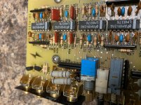
Having finished a modified curved wall version of the Zaph Audio ZRT 2.5 towers a year ago I have caught the bug and have been planning my next build. I want to build from scratch without a kit. Designing a passive crossover seemed a bit too daunting so I decided to go with an active crossover and make use of a miniDSP 10x4 HD.

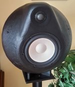
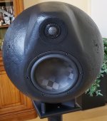
Below is a picture of my Curved ZRT’s. I am really happy with the sound that these things produce, they have replaced Dynaudio Contour 1.4LE’s (and Contour 1.8 v2 before that) and are a major step up from either.

Curved Zaph Audio Based ZRT 2.5 - Google Photos

With the ZRT I laminated the sides with seven layers if 3mm MDF to get the curve. This time I need to build multiple chambers, so thought I would try building it up as a series of 25mm horizontal sandwich slices. I am using dowel spines around the outside in order to provide support, and to help line everything up. Not the most economic method as there is a lot of waste, and there is a lot of routing involved, however it does give me a great deal of freedom in the design.
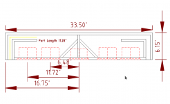
Sketchup design
Google Photos


For this build I have chosen the following drivers installed in this configuration
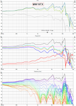
Upper Bass - ScanSpeak 22W/8851T-00 8"Revelator Woofer
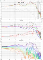
Midrange - ScanSpeak 12MU/8731T-00, 4" Illuminator Midrange
Tweeter - ScanSpeak D2908/7140 Beryllium Dome Revelator Tweeter
Midrange – Another 12MU/8731T-00 wired in Parallel with the one above (MTM)
Lower Bass - ScanSpeak 32W/4878T Revelator 13" Subwoofer

A few pictures of the build so far
Hugh stack of around 100 slices of 25mm MDF ready to start assembling, will cut out the centres as I build it up..

Google Photos

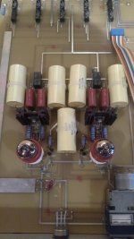
Starting to come together this is the main chamber for the Scan-Speak 32W/4878T Revelator 13" Subwoofer. The port can be seen coming up from the bottom of the chamber, it will be a L slot that comes out the front below the chamber.
Google Photos

By cutting as a series of slices, bracing is pretty easy to include in any shape I want, this one is designed to go around the back of the 32W
Google Photos

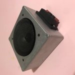
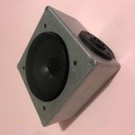
The small cylindrical chamber is for a Scanspeak Illuminator 12MU/8731T-00, 4" Midrange. There will be two of these, another above the tweeter in a MTM D'Appolito arrangement. I made it this shape as from what I have read it produces less internal reflections.

https://photos.app.goo.gl/7JkJfan0lMyqGMwp1

https://photos.app.goo.gl/V4Lbr9SwO5uEBpas1

Trying to decide where to next, either build the base/port assembly or the tweeter section. It is going to be mounted sloped backwards, with the tweeter section vertical and the upper section sloped forward. The next stages therefore involve creating a wedge structure for each end.

DIY sub recommendations

Looking for sub setup to go under cabinet. Space I have to work with is 7.5" tall 12" deep and 34" wide. I can get right at 8" tall and 10" deep letting box go up behind face of cabinet. I was thinking something like pony sub etc. And double it basically building two in one piece. Budget for sub or subs and crossovers around $200 would be great. I am a wood worker and metal fabricator with many years running car audio shop. Just say that as a complicated box design that makes smaller less expensive subs do the job I would love.
Another though was to see how much room is in bottom of the cabinet and building something to slide in it. But not sure on vibration noises.
Hk3390 reciever . Set of cabasse antigua 222's right now. Will be building overnight sensations MTM's after sub to replace them. Room is 15x24 . I sit 10ft straight from speakers. I like blues and classical older music from frank Sinatra to queen and so on. Wide range I know. Blues is my favorite and most played.
Looking to do a 2.1 system I can also use for movies. I use just the cabasse at moment. Sound bar in pic needs to go to garbage. Lol
Side note, what's opinion on center channel? And do you think the sensations is enough listening at moderate levels? For reference I am happy with volume of the Antigua's. Just moved living room into this configuration though and want to do something custom. 20200108_113651.jpg
That's all the details I can think of. If there's questions on something please ask. I am very serious and not just day dreaming and respect alot of your opinions.

FD51-4OS 50mm 3D Printed, Open Source Driver

Hello everyone

FD61's development is still ongoing from a look and sound point of view. This driver however is completely different.

An externally hosted image should be here but it was not working when we last tested it.


FD51-4OS is an educational driver and allows you to get hands on with driver assembly. With the ability to print in different materials, you can see how the performance differs. On top of this, my normal frequency response and T&S results are available.

An externally hosted image should be here but it was not working when we last tested it.


An externally hosted image should be here but it was not working when we last tested it.


Frequency response is in my Twin Bluetooth Vented speaker cabinet. Due to the drivers very high Q of 2.4, the chassis outer walls are made thin to create high leakage. As mentioned, this is a educational design, and not competitive

img_20200104_155319.jpg


The only components required which are not 3D printed are 2 magnets, wire, and some glue. Details on exact parts and filaments I have used can be found on my website, along with the download files themselves.

Design, Develop, Produce, Innovate

I have also made the design compatable with Thomas Sandladerer's M3-SK project, allowing you to use this to try out sealed, vented and passive radiator designs with different internal volumes to see the difference.

Putting this up on here just in case any of you would find this interesting. I also have some recordings done on a Blue Snowball microphone uploaded so you can get an idea of what these little things are capable off.

YouTube

YouTube

YouTube

Thanks for your time and looking 🙂

Paul

Passive filter question

I have a nice full range driver that Nelson Pass said might benefit from this network that provided 4db of shelving at 2.5k. But after I do that I need to attenuate the full range driver 2.5db. Shure a L pad using a 1.33 ohm resistor and a 16 ohm resistor between the filter and the full range driver will do the trick but is there a better way ?

Attachments

  • SAL8 OB PASSIVE W FILTER.gif
    SAL8 OB PASSIVE W FILTER.gif
    16.2 KB · Views: 108

Bic Beam The box FM 10

Dear friends, and, I would add, brave self-builders, I have a self-switch past limited to only two small pairs of boxes and nowadays I simply assemble the slots for my system. From the height of your knowledge, and know that I have done research of all kinds, do you think you can help me?
My target is "Clone Bic Beam The box FM 10 Antenna"
The material collected on the web shows only the exterior, I found an old article on Radio -Electronics March 1978 page 58,

https://www.americanradiohistory.co...ronics/70s/1978/Radio-Electronics-1978-03.pdf

Then nothing. Now I ask for your help.
Thank you Franciscojose

Soekris DAM1021 and Amanero I2S - No Lock

Hi All,

Just put together the latest Soekris dam1021 DAC with Amanero I2S USB adapter. Not getting a lock.
Using this page as a build reference. https://hifiduino.wordpress.com/2015/03/16/soekris-dam-1021-r-2r-dac-users-guide/

- J2 Voltages are ok. Using adjustable voltage reg set to 10v dc.

- Supplied 3.3v from Amanero I2S board to DAM1021.

- Audio output taken from raw L&R.

- Music server Daphile software recognizes the Amanero combo board and Amanero is able to be selected in the Daphile software.

- Default auto-select of source in use.

- Tried 3 different USB cables, all non-audiophile type, probably USB 1.1.

- Tried 16 bit and 192 bit music tracks.

Are the isolated grounds on Amanero boards pins 13,14, and 15?
Does the lock happen only when it detects a track or the dam1021 detects a source?

Any tips would be helpful,

Thanks,

Vince

Modifying a 12ax7 HiFi valve preamp to be a guitar preamp

Hi,

I've got a HiFi stereo preamp with two 12ax7 valves. Attaching the schematics (the schematics uses 12au7 as the second valve, but I've put 12ax7 there as well, they seem to be compatible and 12ax7 gives more gain), it shows one channel.

I want to make a guitar preamplifier from it. I've been looking at some guitar preamp schemes on the internet and it seems like I mostly need to change some resistors (to the ones with the lower resistance), but as I'm not really experienced in the area, I am asking for advice.

The goal is to keep the preamp stereo and have two independent channels for two different instruments, and feed the result to a DAC (to digitally process it further).

Another thing I want is to supply each channel with two potentiometers: one for the gain (between the valves?), another one for the master volume (after the valves). To go from reasobably clean to reasonably crunchy being able to maintain the proper output level.

Could you recommend which resistors need to be changed? As for the gain and master volume I want to replace the two 470K resistors from the scheme, with 1M log pots — are these the correct targets for gain and volume?

Needless to say that as it is it works when I connect something like the headphones output, but when I try to connect the guitar, I cannot hear it.

I would appreciate any advice.

Attachments

  • diykit.jpg
    diykit.jpg
    22.9 KB · Views: 898

The moving impedance landmark?

Is there a thing and a common issue hiding in sim vs reaity vs RTA sweep and even then its not clearly represented Or even considered?

As stupid as that sounds, why then do i find a strong element vaguely attached to many designs that i cannot figure out, nor can i try to very well?

A tapped vs untapped pipe horn waveguide thing. maybe more specific but the name doesnt matter. We dont agree anyhow, or they dont, or whoever?

Why does the Roar or (Hroar) helmholtz? And why dies it sound the way it is described by its founding fathers? why does paraflex have a somewhat similar nature it seems and yet its also an arguably good or bad design as well?

why do some swear by things they can't prove in a sim or otherwise?

Why is a real bass horn impossible? But a funky single impedance lingers in so e designs depending on whos asking or looking?

if nobody argued could we agree theres something still inside a tapped Horn thats not being observed in its sim? or that akabak doesnt tell anyone who wants to look either?


Is the folded horn thats analyzed and simmed unable to tell us what we sometimes think we might hear(if we try to in many types of designs including tapped or compounded?


If a suggestion box was left on the table so nobody had an care in the world about anonymously suggesting something, then i wanna dump a bunch of notes in it!!

- the pressure null in transient or musically dynamic(?) behavior will induce a helmholtz action in the areas of the most interesting and unique tapped or compounded varieties. without suggesting anyone specific persons ideas, but acknowledging some fun and exciting designs, theres a ‘keystone, Karlson, Hroar, Paraflex alt configuration type of way to twist and contort any of those into a lot of similar commonality if you arent specifically interested in a single one of them, instead you blindly dig through assumptions and find many things and similar to them all is tapped.. with a chamber and/or more distinct impedance landmarks that are not in any sim, because there's no change passing through the areas that are or will be once they are long enough to be when a certain ‘bass note’ frequency zooms by or through?

call it previous to approaching phase, or harmonics from one note in a pipe to the next note, or ‘Z’ to ‘Z’ not in a ‘sweep’ or random pinknoise, but even an offset driver ‘TL’ has a hint of the things that occur or can occur given a certain pressure thats actually a lot more than just a sum of constructive vs destructive alignment in a reflection from a closed end or a flat 180 folded version of that?

Whats ‘really’ happening in a tapped pipe (or chunky horn sorta??) thats got dumbies like me who have ZERO acoustical education or experience, falling by chance into this uniqueky wonderful ‘sound’ making thing and about a year or two in discovering theres something ‘missing’ and yet its sortof not if you arent particularly attached to anything except ‘unique’ or potentially? IE: it requires some above average motorforce and drivers willing to exploit that they are in the right ‘VAS’ size or shape directly surrounding the cone or felt by it as if it was a cushion on the F/A felt from the environment through over the Sd from whatever the environment was ‘at a particular frequency?

how is all that in any sim? Is it ever slightly?


And why do we argue what nobody will accept. You cant prove what you can't sim. never gonna change that. or the idea its not true. Cause i can't hear youre box and driver or measure it, but i cant see most of what you love about it in a sim either. Maybe if everything is flat ill agree you have a nice ‘EQ’ to make work out in howevef you wanna... Even if i think its in ‘tapped and squeezed or offset and spit out?? Is that because we cant sim exactly what im talking about? Because its folded up. Or because of changing frequencies throughout the box regardless of electrical intervention?

sorry so long, but Brian Steeles boxplans long ago stuck an idea into that very thing they so nicely can point out of you need to or want to use them... Wheres the pressure null at in this box im folding? or do i even care? And should i? since i assume he comes from a long love of offset chambered or sealed bass, i assume thats why he is so into the specifics of folding instead of just fudging the details into carpentry excuses or corner variances. As we could if we didnt see the excessive details of suggestions in a sim that made us all slightly OCD of our OCD we didnt otherwise have or consider?

Assuming a waveguide or a corner shape is to get rid of something is to assume you know what youre getting rid of. And if it were up to me id make sure i filled my corners with angled braces that were perferorated and full of stuffing In every single one. Or NONE at all. but not one or the other!? That ASSuning one thing? youre sim of a fundamental is all there is and all that youll hear no matter what? And ‘tapped’ is MORE than a corner to a long long fundamental. its got a backwave we are assuming is now at dead center of the ‘pipe’ in LENGTH?? Its even there to see as the unfolded unfrequencied design we have constructed without realizing any reality we are overlooking and then guessing its room gain or its boundary here or there but also half of it or double pf it is missing inside the sim if its placed in and offset. And RTA will say what im suggesting. it might do the opposite shape in reality vs your sim. but if so, you can expect it will do BOTH at any particular ‘music’ no matter what or when, because the conditions for both exist obviously(to those who look or try to)?

helmholtz or qw resonator is not a guess, its a transient in a tapped pipe thats mysterious and folded up to a vent exit or dead end, as compared to the basic well defined straight pipe or sealed long twisted and stuffed one. Those ate matbe a bit more ‘simmed’ and can be.

tell me im wrong please. im having far too much trouble trying to show it or prove how to even in other abbreviated sims of the chunks ....

Hunt for budget DAC in today's competitive world

Hi Everyone,
So I fried my Allo Boss, I don't know, how. It just stopped working while playing music and never came back to life. I was pretty happy with the DAC.

Now it gives me a chance to hunt a new budget DAC or get the same Allo Boss.

Seeing the market of budget DAC's, there are Pelothra of options. I would definitely like to use Raspberry Pi as a network streamer. So will use its USB or I2S output. Considering I already have experienced Allo Boss, what are my options.

Budget DAC for Desktop options.

1. The same Allo Boss and I2S combo.

2. Modi 3+ and Raspberry Pi 3B USB or Raspberry Pi 4 USB
What they updated from Modi 3 to Modi 3+, anyone has any idea?

3. Khadas Tone Board and Raspberry Pi 3 or 4 USB.

4. Topping D10 and Raspberry Pi 3 or 4 USB.

5. Topping E30 and Raspberry Pi3 or 4 USB.

6. Going DIY and modifying the ESS 9038Q2M board as suggested by Mark in the ESS DAC thread. I am fine with DIY.

7. Any other better combination at around $100. This is my budget. +- $10.

Which is better for USB output Raspberry 3 or 4? Some say it's better in Raspberry Pi 4 as USB and LAN bus are different, some say otherwise. So it's kinda debatable. Any help here would be appreciated.

So guys please help me with this.

Thanks,
Simar

First Post, Dynaco ST-150, Topping D50s

This is my first post other than my intro post and I’m unsure if this is the right forum for it, so please correct me if it should be elsewhere.
I recently acquired a very nice Dynaco ST-150 which I’m going to refurb, but which works well at present. I wanted to try it with a Topping D50s dac. The chain looks like qobuz->roon->topping d50s(usb)->dynaco st-150->elac dbr speakers.
This is in a small den. The dac ouput is 2v at 0db and the st-150 is rated 75w rms into 8 ohms at 1v in.
To achieve 75db at my listening position, With roon dsp volume at 0db, I have to lower the output on the dac to -10 to -15db depending on source material.
So my question. Setting the dac at -6db, I should be getting about 1v out with roon at 0db.
Is it best to vary the rest of the volume with roon’s 64 bit dsp volume control or is it better to leave roon at 0db and vary all volume with the topping d50s volume control?
My apologies in advance if this is a stupid question.

Thoughts on basic (cheap) active speaker

I'll start by stating I'm not an audiophile and initially I am trying to understand if I can improve on the sound quality of a speaker I have just bought for less $$ and have something I can say I built. If I can hear a difference then I might try to improve on that.

I have seen a lot of new builders failing to know exactly what they want so I have tried to define below what I want to do, it's not pushing the boundaries of audio science and if there are more appropriate forums I should look at please let me know, this does look like a forum where expectations are high but we all have to start somewhere.

I'm happy to use proven designs to get the first build under my belt as I learn about all of the variables.

Being in Australia we seem to pay more and have less choice of components so I'll call a US$250 budget for components, I'll use mdf to build to enclosure (not included in budget).

So I want to build a single speaker/amp with the following minimum specs.

20W power
frequency 45 -22,000Hz
2 way
Sits in a box about 166 x 320 x 180 mm
RCA and line input

Nice to have
WiFi capable
Bluetooth capable

The speaker I have has the following drivers
Tweeter: 2 x 3⁄4” textile dome
Woofer: 5.25” long throw

I can work with wood and solder and measure things once and cut things wrong

I have identified these components and kits which give me the opportunity to build a matching pair or to build two speakers using different designs with the same components to see the difference. Would appreciate thoughts...

Soundlabs Group Aria Speaker Kit
Stereo 20W Class D Audio Amplifier - MAX9744 Australia

Belles 21A preamp upgrades?

On a Belles 21A preamp, I have to remove the motherboard to replace a bad selector switch relay.

Everything else works well, and it sounds fine, but it is 17 years old. As long as I am in there, should I consider any upgrades? I am thinking along the lines of the large yellow Amphion 2.2 uF coupling capacitors.

Attachments

  • 21A motherboard.jpg
    21A motherboard.jpg
    158.9 KB · Views: 117
  • 21A caps.jpg
    21A caps.jpg
    209.4 KB · Views: 109

Help with replacing a tweeter with a full range driver?

Good evening everyone. So I have decided to put most of my projects in the back burner in-till I have my wood lathe delivered..( hopefully in the next few weeks)? So the tweeters I want to replace is an older set of seas fabric dome tweeters. So I am looking at the sizes 1 to 2 1/2 inch full range drivers that are 8 ohms. If the db is low no big deal. I can add another one in the back to to raise the db of the drivers. So I already have a 6 1/2 driver in mind. The Mark Audio's CHR 120 silver drivers. I guess am asking for help because I have never used a full range driver lower then 3 inch's. I have a cap that can be put on the small full range drivers. It might be 500 hz? Well please let me know what you think about this idea? Am asking before I spend the money to up date his speaker's. The reason for the update. Little ones have had their day with the speaker drivers and it's not pretty or sounds right. Jeff

High mains voltage and tube life

Today I measured my mains voltage at 240+V.

My amp is built for 220V. It is an EL34 PP that uses 12ax7 and 12au7 on the input stage. I pulled out a pair of EL34 and measured the socket and found the unloaded heater secondary to be at 7.04V.

I don't know how high is the heater voltage if they are loaded, but theoretically a 6.3V windings would give about 6.87V.

I opened up the amp to see if there is any 230V or 240V primary windings. It does not appear to be the case.

I can't put my hand on the power transformer for more than a few seconds, my guess is it is around 70 deg C on the outside. Not great, but I guess it is not too much of a problem?

So tube life would be reduced at elevated heater voltage. My question is how significant is this? If it is something like 10-20%, I would think I can live with it. If it is something like 50% then I think have a problem.

If I were to get a 230->220V transformer, do I want EI or toroidal? What wattage do I shoot for? Amp is rated at 230W.

Thank you for reading.

The moving impedance landmark?

Is there a thing and a common issue hiding in sim vs reaity vs RTA sweep and even then its not clearly represented Or even considered?

As stupid as that sounds, why then do i find a strong element vaguely attached to many designs that i cannot figure out, nor can i try to very well?

A tapped vs untapped pipe horn waveguide thing. maybe more specific but the name doesnt matter. We dont agree anyhow, or they dont, or whoever?

Why does the Roar or (Hroar) helmholtz? And why dies it sound the way it is described by its founding fathers? why does paraflex have a somewhat similar nature it seems and yet its also an arguably good or bad design as well?

why do some swear by things they can't prove in a sim or otherwise?

Why is a real bass horn impossible? But a funky single impedance lingers in so e designs depending on whos asking or looking?

if nobody argued could we agree theres something still inside a tapped Horn thats not being observed in its sim? or that akabak doesnt tell anyone who wants to look either?


Is the folded horn thats analyzed and simmed unable to tell us what we sometimes think we might hear(if we try to in many types of designs including tapped or compounded?


If a suggestion box was left on the table so nobody had an care in the world about anonymously suggesting something, then i wanna dump a bunch of notes in it!!

- the pressure null in transient or musically dynamic(?) behavior will induce a helmholtz action in the areas of the most interesting and unique tapped or compounded varieties. without suggesting anyone specific persons ideas, but acknowledging some fun and exciting designs, theres a ‘keystone, Karlson, Hroar, Paraflex alt configuration type of way to twist and contort any of those into a lot of similar commonality if you arent specifically interested in a single one of them, instead you blindly dig through assumptions and find many things and similar to them all is tapped.. with a chamber and/or more distinct impedance landmarks that are not in any sim, because there's no change passing through the areas that are or will be once they are long enough to be when a certain ‘bass note’ frequency zooms by or through?

call it previous to approaching phase, or harmonics from one note in a pipe to the next note, or ‘Z’ to ‘Z’ not in a ‘sweep’ or random pinknoise, but even an offset driver ‘TL’ has a hint of the things that occur or can occur given a certain pressure thats actually a lot more than just a sum of constructive vs destructive alignment in a reflection from a closed end or a flat 180 folded version of that?

Whats ‘really’ happening in a tapped pipe (or chunky horn sorta??) thats got dumbies like me who have ZERO acoustical education or experience, falling by chance into this uniqueky wonderful ‘sound’ making thing and about a year or two in discovering theres something ‘missing’ and yet its sortof not if you arent particularly attached to anything except ‘unique’ or potentially? IE: it requires some above average motorforce and drivers willing to exploit that they are in the right ‘VAS’ size or shape directly surrounding the cone or felt by it as if it was a cushion on the F/A felt from the environment through over the Sd from whatever the environment was ‘at a particular frequency?

how is all that in any sim? Is it ever slightly?


And why do we argue what nobody will accept. You cant prove what you can't sim. never gonna change that. or the idea its not true. Cause i can't hear youre box and driver or measure it, but i cant see most of what you live about it in a sim either. Even if i think its in ‘tapped and squeezed or offset and spit out?? Is that because we cant sim exactly what im talking about? Because its folded up. Or because of changing frequencies throughout the box regardless of electrical intervention?

sorry so long, but Brian Steeles boxplans long ago stuck an idea into that very thing they so nicely can point out of you need to or want to use them... Wheres the pressure null at in this box im folding? or do i even care? And should i? since i assume he comes from a long love of offset chambered or sealed bass, i assume thats why he is so into the specifics of folding instead of just fudging the details into carpentry excuses or corner variances. As we could if we didnt see the excessive details of suggestions in a sim that made us all slightly OCD of our OCD we didnt otherwise have or consider?

Assuming a waveguide or a corner shape is to get rid of something is to assume you know what youre getting rid of. And if it were up to me id make sure i filled my corners with angled braces that were perferorated and full of stuffing In every single one. Or NONE at all. but not one or the other!? That ASSuning one thing? youre sim of a fundamental is all there is and all that youll hear no matter what? And ‘tapped’ is MORE than a corner to a long long fundamental. its got a backwave we are assuming is now at dead center of the ‘pipe’. Its even there to see as the unfolded unfrequencied design we have constructed without realizing any reality we are overlooking and then guessing its room gain or its boundary here or there but also half of it or double pf it is missing inside the sim if its placed in and offset. And RTA will say what im suggesting. it might do the opposite shape in reality vs your sim. but if so, you can expect it will do BOTH at any particular ‘music’ no matter what or when, because the conditions for both exist obviously(to those who look or try to)?

helmholtz or qw resonator is not a guess, its a transient in a tapped pipe thats mysterious and folded up to a veby. as compared to the basic well defined straight pipe or sealed long twisted and stuffed one. Those ate matbe a bit more ‘simmed’ and can be.

tell me im wrong please. im having far too much trouble trying to show it or prove how to even in other abbreviated sims of the chunks ....

Soundstream AR1.2500D noisy/distorted output

Good day gents,
I got this SS AR1.2500D (similar to SLA-1500), completely rebuilt, PS, outputs and driver card.
The amplifier currently passes distorted audio. with my 8ohm dummy load hooked up it passes clean audio up to around 6/7vrms, after this it gets distorted.
I've attached the waveforms for both high side and low side output FETs (no audio into amplifier). I've tried numerous LC filter values/combinations to no avail.
I'm seeing the high side has a notch in it. will this be the contributor to the noise/distortion?

Anyone got a remedy for this?

Attachments

  • HS gate drive.jpg
    HS gate drive.jpg
    1 MB · Views: 85
  • LS gate drive.jpg
    LS gate drive.jpg
    1 MB · Views: 78
  • noisy output waveform.jpg
    noisy output waveform.jpg
    1 MB · Views: 131
  • IMG_8451.jpg
    IMG_8451.jpg
    1,011 KB · Views: 88
  • IMG_9497.jpg
    IMG_9497.jpg
    989.8 KB · Views: 97

Duke's Build Thread

I've populated the board, built the chassis, now all thats left to do is wire it up! Posting some pictures of progress, and would love some constructive criticism. Any idea of the best place for my choke and capacitor? Will volume pot be ok by the power side?

I find this forum to be so incredibly valuable. Love the pictures, and parts lists, that have been posted. Most of my questions have been answered by reading and re reading posts. Hope this helps someone as well.

Samsung HT-P1200 - no central unit - volume control

Hi All,

That's my first post here.

Short introduction to this system:
1. DVD player - all inputs are here (hdmi etc.) - I do NOT have it.
2. 5 speakers - connected to Subwoofer
3. Subwoofer (built-in amp for all speakers)

Additionally I have 5.1 D/A converter - optical to 6 analog channels.
As you can see it's possible to connect those analog inputs directly to subwoofer amp and system works, speakers play.

BUT - it's pretty silent. I tried to connect MP3 player as analog input, and with maximum volume on it, loudness is just acceptable.

Question:
How can I add volume control to this system?
- I have all schematics diagrams
- I tried to use impulse knob to connect it to VOL+/- (see picture) with no effect.

Attachments

  • Zrzut ekranu 2020-08-05 o 08.57.24.png
    Zrzut ekranu 2020-08-05 o 08.57.24.png
    98 KB · Views: 311
  • IMG_9279.JPG
    IMG_9279.JPG
    925.5 KB · Views: 428
  • IMG_9302.jpg
    IMG_9302.jpg
    956.9 KB · Views: 282
  • IMG_9280.JPG
    IMG_9280.JPG
    573.5 KB · Views: 224

Passive eq across load / speaker

So.. I have made a couple of boxes for testing...
Aluminium 120mm x 120mm x 60mm approx project boxes
Box 1 is an amplifier
Its has a 2 channel class d amplifier board, a voltage cut off board, a makita power tool usb charge adaptor glued on so it can run of 18v power tool battery
in line fuse to protect battery
phono inputs, speakon and spring terminals for speakers
power switch and led and fuse blown led

Box 2 is the same aluminium box but with a 4 inch car speaker in it
speakon connector and spring terminals

I am an AV engineer and these will come in handy for test fault finding

the question.... the car speaker sounds naff in such a small box
not so bothered about the lack off bass but the massive peak around 1khz

I was planning to run a power resistor in series with the speaker anyway to offer it some protection from high power 2kw plus amplifiers

could I reverse an bandpass filter in parallel with the speaker instead of in series with another resistor to attenuate the nasty peak at 1khz?

the driver is 4 ohms nominal haven't measured it but I'd bet its a lot higher at 1khz! based on 4 ohms I guess I would want something like a 1mh inductor and a 40 uf cap? but it would probably need a bit of trial and error !
Is there anything wrong with this design

I don't want the test box to be an amplifier destroyer! That creates more work this is meant to simplify little fault finding jobs!!

Its never gonna sound great but this sounds worse than the makita site radio!

Attachments

  • image0.jpg
    image0.jpg
    426.7 KB · Views: 54
  • image1.jpg
    image1.jpg
    416.4 KB · Views: 60
  • image2.jpg
    image2.jpg
    467.2 KB · Views: 61
  • image3.jpg
    image3.jpg
    447.7 KB · Views: 58

JayShoe's Pro Audio Series - Teensy 4 ADC & DAC Audio Shield - TLV320ADC5140 PCM5242

JayShoe's Pro Audio Series - Teensy 4 ADC & DAC Audio Shield - TLV320ADC5140 PCM5242

Hello Friends,

I'd like to introduce my Pro Audio Series ADC and DAC modules for the Teensy 4 and Teensy 4.1. These modules were designed to provide high quality audio within the Teensy Audio Library ecosystem. They offer single ended and balanced audio inputs and outputs for audio mixing, musical instruments, effect processors, guitar pedals, and pretty much any other audio processing task you are working on. They sound great, and are easily integrated into your project.

attachment.php


attachment.php


THE KICKSTARTER CAMPAIGN IS NOW LIVE:
JayShoe's Pro Audio Series - Teensy 4 ADC & DAC Audio Shield by JayShoe — Kickstarter


The ADC is a TI TLV320ADC5140 and the DAC is a PCM5242. I posted more information in the campaign but feel free to reach out if you have any specific questions that I can answer. I hope to post additional updates as the campaign progresses. Thanks for your interest and support!

- JayShoe


Tags: Audio Shield, Audio Codec, Audio DAC, Audio ADC, TLV320ADC6140, TLV320ADC5140, TLV320ADC3140, PCM5242, Teensy Audio, Audio LIbrary

Attachments

  • JayShoes_T-Pro_Audio_Series_ADC_DAC_AUDIO_SHIELD.jpg
    JayShoes_T-Pro_Audio_Series_ADC_DAC_AUDIO_SHIELD.jpg
    289.7 KB · Views: 748
  • JayShoes_T-Pro_Audio_Series_ADC_DAC_AUDIO_SHIELD_totalsm.jpg
    JayShoes_T-Pro_Audio_Series_ADC_DAC_AUDIO_SHIELD_totalsm.jpg
    80.2 KB · Views: 761

Feebay

I'm really disappointed with the new "managed money" policy at ebay. Now they will not send money to PayPal, but want to totally control it and want your bank account number to send money to. IN THIS AGE of cyber security, I don't want my account given to anyone. With the selling fee's they are asking, it may be time to say goodby. To bad, I've been with them since the beginning.

Year END Reflection - 2020

2020 was not an easy year for all of us.

Personally, I retired from my CPA job since September and worked 24/7 for the last 4 months for my DIY hobby business.

Although this 2020 brought many new challenges, I must say this year has also brought many surprises – It is like this Chinese idiom (天時地利人和) meaning an intersection of the right time, place, and people. After 15 years in the DIY business, 2020 has turned out to been the most successful year.

I want to take this time to thank you for your trust and support for making the TU-8600S project workout so successful. Your $1,200 upfront payment is very meaningful for me. It conveys your trust for what I am doing. A lot of DIYers said to me, “Victor I can pay the full amount.” WOW… That says a lot to me.

With all that said, I leave you with a beautiful music from a 16-year old pianist – PAUL JI. Surprisingly fluid playing of these very well-known pieces. A pleasure from start to finish.

Paul Ji plays Liszt: Grandes études de Paganini, S. 141: No. 3, La Campanella - YouTube

I wish all readers a happy holiday and audio success in 2021!

By the way, the review of Elekit TU-8600S will be available soon from Stereophile in early 2021.


flags_1

Guitar end amplifier as base for HiFi

Hi there,

I'm new to the whole tube story, but I just wanted to give it a try. While I was researching all around, discovering the abyss of output transformers and their costs I stumpled over power guitar amplifiers.
To be specific the Engl Tube Poweramp 840/50.
It's using 6L6 as PP in the output, all composed in a 2HU 19" case.
All that for €500 in good used condition.

To the ones who know: To me the OTPs seem a little small for 50Watts of output power and above all, simple EI cores.
What is to expect from them? Are those instrument amplifiers even specified for (almost) Hifi, so roughly 20Hz to 16Khz?

Could that be a good basis over all the chinese amplifier kits?
Or are the OTPs not up to the HiFi job?

BR, Markus

P.S.: I'd have no worries about the fan 😉

Attachments

  • 964_-1288771639.jpg
    964_-1288771639.jpg
    61.3 KB · Views: 184

Proton 1100 Preamplifier Service Manual

Greetings!

After searching for quite some time, I have finally tracked down a service manual for my Proton 1100 preamp.
I love this preamp and now I feel confident to get into refurbishing it.

I downloaded it from here, for about $16. It has schematics, board layouts and parts lists. I am happy with the quality.

Hope this information might be useful to someone!

Rgds,
blakkshepeaudio

https://secureiti.com/servicemanuals/ServiceManual/PROTON/1100 PREAMPLIFIER/609958/detail.aspx

Better woofers for Optimus Linaeum LX5?

I have a mint pair of Lineam LX5s, and while their high end is amazing, the lower octaves leaves a little to be desired. I've stuffed the ports with straws as suggested by others and that helped somewhat. I'm wondeing if anyone has upgraded the LF driver in these puppies? It's a 5 inch polyproprolene job and looks pretty cheaply made.

What did you use and how were the results?

Phono preamp input bleeds at moderate volume through other inputs.

Hello,

I recently purchased a used Destiny Phono MM Preamp. When I play my records and switch inputs I can hear the phono input play through the other inputs at moderate volume, independent of the volume control. Is this much input bleed expected on this circuit? It is also noticeable but at much lower volumes when playing from my DAC. I'm concerned there might be something wrong with Phono preamp, or something else is amiss.
I've checked the ground turntable ground cable is connected to the chassis, and measured 10 ohms from the chassis to the RCA ground outer conductor). Any help is appreciated 🙂.
Input relays are Fujitsu RY-5W-K
https://www.mouser.com/ProductDetail/817-RY-5W-K/

Attachments

Projects by fanatics, for fanatics
Get answers and advice for everyone wanting to learn the art of audio.
Join the Community
507,844
Members
7,890,428
Messages

Filter

Forum Statistics

Threads
406,357
Messages
7,890,428
Members
507,844
Latest member
Amirbutt