How to replace belts on Marantz cd94.

Hello all.
Can anyone help me? In explaining step by step how I'd go about replacing myself all four belts ( which I have ready to swap) in my NOS/NIB Marantz cd94.
I do have the service manual but am inexperience with such and so its all rather double dutch to me!
I would however like to be able to do such 'surgery' myself but would need a rather step by step approach....first remove THIS screw then this one .. only then.... etc etc.
I expect this may be a bit of work for someone so if anyone wantsto private message me maybe we could work out if neccessary some appropriate fee I would pay to enable me to replace the belts both correctly and without scratching /marking what is an unused and therefore mint example of this classic 80's player. (this being one reason I'm nervous to hand it over to an outside tech!)
Thank you in advance Philip.

Making a Vintage class A/B Lighter

I have two Peavey CS800 amplifier amps that someone dropped off and never called or came back for. Ten years later, during the pandemic, I now have the time to take a look at them.
These are beasts. I estimate they weigh ~ 65 pounds most of which is a 6x6x7" E-core power transformer, however, they are well built, use quality components, and are easy to service. The size and weight are quite objectionable of course but they are powerful using a +/-80V bipolar power supply.
I'll check the huge filter caps for leakage an reform if possible. I'll remove the crowbar protector. I may replace the few op-amps with modern types. Initially I'll borrow parts from one to repair the other and, if I like the way it sounds, perhaps I'll purchase parts to repair the other.
I'm thinking of buying one of these bipolar switching power supplies that can be had for under $50.00 on ebay to replace the tranformer/rectifier. This would knock off the majority of the weight.
Have any of you tried this?
Also, is PTC protection device a good sub for the triac crowbar circuit?

Loud buzzing sound origin

Hi,


I've got a bass amplifier that has a fairly loud buzzing sound. I currently live in a fairly old house where there weren't earth in every socket so I thought the buzzing came from the lack of grounding. I installed ground wires to all the sockets and the buzzing sort of stopped or at least reduced.


A couple of weeks ago I noticed the buzzing to be louder again and I also noticed that if I put my hand on the amplifier the buzzing ceased or at least reduced. After some fiddling I also noticed that if I bend the ac cord into a loop the buzzing got reduced too. I thought this is because of a bad ac cable so I replaced the ac cable with another one.


The buzzing didn't stop but I noticed that if I maintain a certain size of loop on the ac cable the buzz cease to exist.

So the problem is actually solved but I'd like to know why is this happening and if there is more elegant solution to it then looping the cable?
Thanks!

Modifying RCA 40-5003 speakers with the Zilch 2.2 crossover

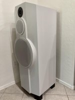
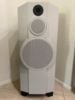
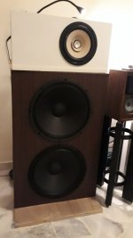
I found a pair of RCA 40-5003 speakers in a thrift store. These are “big brothers” to the well known Minimus 7, I think they were also known as the PRO-X55AV. I’m not sure if they’re the same as the Minimum 77. From the research I could do in the thrift store, they have a 5 ¼ inch woofer in a vented enclosure and use the same tweeter as the Minimus 7 so I assumed I could use the Zilch crossover with them. The cabinets had a few marks but weren’t too bad, and peering into the grille it looked like the foam surrounds were intact (more on that later). They were asking $10, with my senior discount they were $8.50 out the door - not too bad! We were moving into a new house, I thought these would make a decent garage setup. If not, there was little downside.

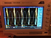
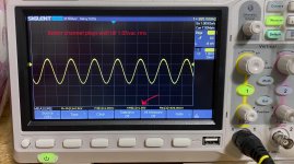
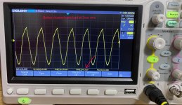
Fast forward a few months, we’re moved in and gotten 90% set up so I pulled the speakers out to see what I was dealing with. First I decided to give them a test with a signal generator to see what the response looked like. I drove them to a pretty decent level at 1 kHz and started going downwards. When I was at something like 60 Hz they started rattling and I noticed some dust flying by the corner of my eye. Uh oh.. a quick glance at the surrounds confirmed they were toast. Oh well, I guess appearances can be deceiving, time to refoam.
I ordered a Simply Speakers FSK-5L foam kit, it required cutting away some of the outer portion of the surround but was otherwise a perfect fit. I cut & glued with all the enthusiasm and skill of a second grader, but after allowing the glue to set up for a day the woofers sounded much better. Luckily you can’t see them behind the metal grille!


NRDRERG.jpg


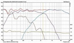
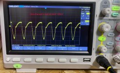
Once this was fixed I could see that the speaker rolled off pretty sharply at 70 Hz, by 40 or 50 Hz there wasn’t much output. That seemed acceptable for a garage system. Listening to the speakers, they were OK, kind of sizzly on the high end and not much detail.


On to the crossovers. I ordered the parts for the Zilch 2.2 from Parts Express.


NHRMy1L.jpg


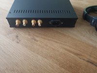
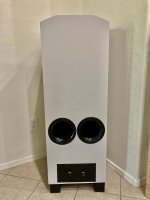
Just like the M7, these had a 0.4 mH in series with the woofer and a 2.2 uF bipolar electrolytic and 0.4 mH in the tweeter circuit. I had planned on removing the stock input terminals and building the crossover on a blank copper clad board with banana jacks on the back. Unfortunately closer examination of the back panel of the enclosure showed that there were a number of posts there – mostly unused – that prevented simply mounting the copper clad flat on the rear of the enclosure.


z5UhQnh.jpg


TC4hdsN.jpg


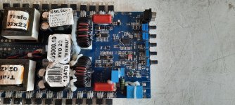
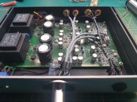
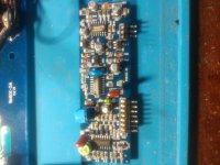
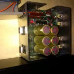
You could cut out the PCB to accommodate the posts but that was more work than I was willing to do. I decided to see if I could modify the stock crossover PCB so I could keep the stock terminals. That turned out to be easy to do.


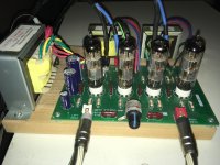
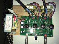
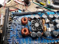
First the woofer circuit, the 0.8 mH stock inductor comes out and is replaced by Parts Express #257-550. The new inductor is much bigger, but it does fit. You can route the wires pretty easily but you have to enlarge the holes with a drill or hobby knife to fit the lead. This removes most of the pad’s annular ring so you have to scrape away some of the solder mask to allow for a secure solder joint. Luckily the removal of the stock inductor leaves a hole in the PCB that allows for a cable tie to hold down the inductor. Some hot melt glue on the inductor flanges further secure it.


h6muI0C.jpg


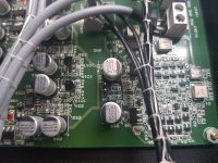
There wasn’t room for the Zobel resistor #015-3 and capacitor #027-422 on the crossover PCB so I simply hot glued them to the woofer’s magnet structure and soldered the leads directly to the woofer terminals.


mzsEWnY.jpg


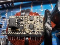
The tweeter was also pretty simple, the stock 0.4 mH inductor remains in place and the 2.2 uF electrolytic is replaced by a 2 uF film cap #027-414. The 1.8 ohm #015-18/47 ohm #016-47 divider (PE didn’t have Zilch’s 2 ohm value) is implemented by standing them up with the 1.8 ohm connected to the input and the other end of the 47 ohm resistor then wrapped around the PCB to a ground connection. The junction of the resistors is then soldered to the 2 uF cap, and all three components are hot glued together to prevent movement.


X6vH61B.jpg


1x77ZPs.jpg

T6dC66Q.jpg

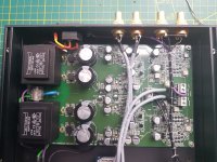
The modded crossover fits in place with no problem, and re-assembly proceeds without difficulty.


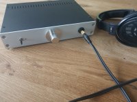
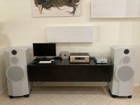
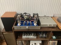
Now to the best part, listening. I set them on the only stands I had handy which were a bit short at 24 inches high. The difference was amazing! Set about 8 feet apart, and 12 feet from the listening chair, the image popped into place very nicely. Vocals were also very smooth. You wouldn’t call the bass extended by any means, but up to levels that made conversation hard it gave a good account of itself. If you really turn it up, you can hear port noise so there are limits.

As my son would write TL;DR the Zilch mods are pretty easy and make a big difference. I’m going to pair these with a Lepai amp and drive them with an Echo in the new garage, this should rock!

SB Audience

Hi,


did anybody of you have experience with SB-Audience-driver?
I did not know SB Acoustics is now going PA.


The 6-Midrange and 15 inch woofer took my interest:
SB Audience :: NERO-6MRN150D
SB Audience :: NERO-15SW800


The mid-range has an unbelievable high BL²/RE/MMS-Ratio of 2,47 and does also include a demodulation ring.
Seems to be maybe a good candidate for "Power-Hifi"-Midrange from 200Hz-2khz and maybe an alternative to other 6,5-midrange candiates like PHL 1120 and AE TD6M.


Does anybody have more background-information about the company SB audience?
Could not find any information about them in net.

RT-81 mod wiring help

Need help with modding my RT-81, going to direct wire the RCAs to the wires going to the arm board, I see there's a seperate left and right +, seperate L and R ground, and a arm ground. On the main circuit board there's a pretty solid ground wire going to the bearing housing. My question is do I direct wire the L and R + - to the RCA cables, and the tone arm and bearing housing to the post on the back for ground? Can't really follow the board all that well, and the only other post online the guy just solders in jumpers, but kinda feel this is paralleling the circuit thats already there and theoretically altering the sound. Working on DIYing the plinth to a marantz looking style. Hopefully will spin again tomorrow!
View attachment 914381View attachment 914382

HH S500D Schematic

Hi,

I have a HH S500D which is getting a bit long in the tooth and could probably do with some TLC. It plays music okay at ~half power for around 90 minutes and then progressively sounds distorted.

Please could someone point me in the direction of a schematic for this amp, particularly the AS00008 O/P Driver PCB. I have searched threads on diyAudio and the wider internet, so have the chassis wiring & O/P Module details. Would like to be ready armed before poking around inside.

Many thanks

Dave

Narrow dispersion for desktop

Hey guys,

I have my desktop in a corner of my living room. Regularly I like to listen to music at my desktop while my family is watching TV. No more explanation needed, I think 🙄.
Is it possible to design speakers for my desktop with a very narrow dispersion pattern? I think about a 2.1 setup with small 2-way monitors next to my screen facing straight to my ears. Just to minimize the SPL spreading to the rest of the room.
Are there drivers with typical narrow dispersion or should I use kind of a horn? Any advice welcome!

Attachments

  • narrow polar.png
    narrow polar.png
    353.2 KB · Views: 115

Multi Entry Horn - Low/Mid Box Only - Sim Help

I'm working on this idea of a MEH cabinet but with mids and lows only. Using Hornsrep screenshots it seems hard to visualize. But I will draw this up as soon as I get some clarification.

Nd Record
uc


ME1 Record
uc


HR Schematic
uc


Regarding the ME1 Record:
I'm assuming HR is using S2 for the location of the entry ports. Is this a correct assumption?

Ap1 and Ap2 I'm not sure about. If I'm just using a 2-inch cutout then both of these values should be the same correct?

Vrc and Lrc seem to have default values. I can't remove them. I was thinking the Nd record governed the horn dimensions as well as the rear chamber. Why is Vrc and Lrc populated in the ME1 record?

S 5 Electronics K 12-G tube amplifier for sale

Tube amplifier in good shape original from Usa.Plug and play option.Tubes in verry good shape.Amplifier is working and sounds great.Original transformer made for Usa 115 volts,but I will give the buyer another transformer for use in 230 to 115 v so the buyers from EU cam use this without problem.Price 150EU plus shipping or best offer.Plese look for data on internet.

Attachments

  • 134806FD-3679-4E80-92C1-11A17E4A4553.jpg
    134806FD-3679-4E80-92C1-11A17E4A4553.jpg
    899.2 KB · Views: 71
  • 29CB8DAA-D795-4DBC-B934-85C2B4BE3B5B.jpg
    29CB8DAA-D795-4DBC-B934-85C2B4BE3B5B.jpg
    846.3 KB · Views: 71
  • B7C07510-3A50-4BB7-A48F-3208E2C920D1.jpg
    B7C07510-3A50-4BB7-A48F-3208E2C920D1.jpg
    956.6 KB · Views: 61
  • 2CE76662-8ABC-4C17-B247-30E497A374B1.jpg
    2CE76662-8ABC-4C17-B247-30E497A374B1.jpg
    992.4 KB · Views: 108

Be careful when buying vacuum tubes

Hi. theese days I am about to spend some money on tube gear. Searching ebay I spot very strange item with insane price.
.
Single Large Triode Tube - De Forest | eBay
.
With more carefull visual inspection of given photos it came out that is NOT in any way the item described in title.
.
That is VT-4-C tube from General electric made in II war era. Surley it is not a 12Kusd?
.
Pleae be careful - and not rush in when bying tubes. Try consult someone with more experiaence and knowlege. I hope this will be of some help?
.
PS
I just could not stand not to by one Leak 12TL+ mono power amplifier yesterday. Same color and else like mine. More than decent amp after replacing old parts. Now I am go to stereo! 😛

Attachments

  • Screen Shot 2021-01-23 at 4.43.49 PM.jpg
    Screen Shot 2021-01-23 at 4.43.49 PM.jpg
    78.4 KB · Views: 306

Sound card FFT question

I have a question about using a sound card for doing distortion measurements. Using Visual Analyzer Visual Analyser I do a calibration with a loopback and then connect up my amplifier. Across the 8 ohm dummy load I have a 20k pot to attenuate the voltage to the line input to prevent damage.


Now the distortion figure changes greatly depending on the line in voltage. So what is the correct voltage to use? Perhaps what voltage the calibration uses?

Interesting output stage from the TDA7293

Hi all,

I came across the TDA7293 output stage in another thread, I think it could make for an interesting discrete design for a very low distortion unity gain buffer.

The reason I think it has value as a discrete solution:

- Uses all N type MOSFETs (could use BJTs as well I guess) so we have more options.
- Simple.
- Low distortion due to the op amp.

Draw backs:

- The op amp could make global feedback networks difficult.
- The op amp supply constrains the voltage swing and thus power of the output stage.

The datasheet is here.

The output stage is attached to this post.

The only thing is I struggle to understand how it works in class AB or with an output load.

If we assume there is a speaker attached and M1 is partially biased for class AB how will it ever source more current than the quiescent bias current. Essentially, the output stage needs to operate in class A. The output will maintain Vo = Vi so M1s Vgs can only ever be the bias generated by Mr. Does this design only work as it's implemented on the same die? It's quite easy to rearrange the circuit into something else but it loses some simplicity and loses the extra gain offered by M2 in the common emitter config.

Any insights are appreciated!

Attachments

  • tda7293_outputstage.png
    tda7293_outputstage.png
    93.8 KB · Views: 126

Allison 3 speakers: looking for help with driver replacement

Hello, I'm new here and I'm looking for someone with experience or advice on restoring a nice pair of Allison 3 speakers. Here's the backstory.
I picked up a pair of these from a nice older guy who had them from new sometime in the 80s. I got them cheap, and they're in very good condition which means I'm lucky. I've enjoyed them a lot since I got them almost a year ago. Recently I noticed that the sound seemed unbalanced, and it looks to me like the mid-range driver (3.5" "fried egg") on one of the units is not producing sound. I haven't gotten the multimeter out or checked the crossover yet, but I presume the voice coil on that driver has died.
Based on my brief research into these speakers, I've learned that these are considered by many to be a very good near-audiophile grade of speaker, but they are also relatively rare, very unique and not easy to repair.
Does anyone have advice to share about troubleshooting and possibly replacing the mid-range driver on my speaker?
Thanks a bunch!

Power stage, replacing old MOSFET, doubts.

I hope this topic has not been dealt previously, in this case I apologize.
I am faced with a personal challenge, I am not a repairer but I have completed studies in electronic engineering, and I can say that I can manage with applied electronics.
I especially like to resurrect vintage objects.
Now I'm struggling with a Hitachi power amplifier, the HMA-7500 MK II, which has mosfet power amps in push-pull. The amplifier was previously grossly remodeled by a scoundrel. 😡
I only managed to get one of the channels back in order, but I found some absurd failures and had to replace the pre-finals, the VAS and even the double op amp of the DC servo loop. Many bjts and most of the fuse resistor were blowed.
Now I have to replace the power MOSFETs, but their availability is a problem (they cost a lot and I am never sure they are not counterfeit items), it is the 2SK134-2SJ49 pair.
The thing I wanted to do is replace them (even if only for testing) with a modern pair of IRFP240-IRFP9240, which however have a higher gate-to-source threshold voltage (2-4V Vs 0.15-1.45V) and cannot go into that light conduction that allows the passage of the idle current (drain current now is zero).
I would think of modifying the R755-R766 and R760-R759 resistors with the aim to drive the modern pair with a right voltage. (please see at pic below)
What do you think ? Any ideas / suggestions?
Thanks a lot in advance
porzione-schema-Hitachi — ImgBB

NE5532 Preamp unused channel termination?

Hi guys,

I'm looking to boost the signal out of my miniDSP so that I can run a lower gain on my TPA3116 amp. I have a 2.1 setup with the miniDSP as an active crossover driving 2 separate TPA3116 amp boards, one running in bridged mode for the sub. I only need to boost the input signal for the sub amplifier.

I have one of these chinese (likely not genuine TI) NE5532 preamp boards coming https://www.amazon.com/gp/product/B07HG37N1X/

716t4z3adwL._AC_SL1000_.jpg


I only need one of the two channels, but I know that OP-Amps are not always happy with one unterminated input/output.

The TI spec sheet says that it is OK to tie it to ground or either supply rail. I was thinking that I would do this directly at the chip on the board, bypassing the rest of the circuit for the second channel. (as opposed to just connecting the input or output of the board to ground). Considering that this is likely a fake and not a real TI chip, do you think it is still OK to do this?

If not, what do you recommend...

I'm sure I'm not the first person with this problem, but sometimes tribal knowledge is the key 🙂

Luxman LV-105 hum

Hello,

I'm having some trouble finding the cause for a hum on a luxman LV-105 (not the u version). Also the right channel doesn't handle any load (dim bulb goes bright and relay opens). Sometimes, not always, the relay keeps kicking in and out without any load connected, at the same time dc offset get up to around 1.5v. The tubes are ok (putting in new ones doesn't change anything to the problem) and the hum is present before them (not in the tone amp though). The caps are all new (checked polarity carefully). Whenever I unplug the connector taking the + and - rails to the equalizer circuit the hum gets slightly lower and the right channel can accept a load again. It looks like the high voltage power supply can't keep up somehow.

Sound Digital SD5000.1D 2OHM

Good Morning,

Right now I have an amp on my workbench that comes with the clip and power LED on, checking that I found the irs20957s were not getting the pwm, I change the lm319 and I get the pwm, however now when I put the remote control, the LED clip blinks 10 times and someone with more experience with these amps can help please, I have it working only with the 12v source in the output or service mode as I would say

Attachments

  • 20210123_111049.jpg
    20210123_111049.jpg
    981.7 KB · Views: 117

DDDAC Power Supply

I just posted a new blog on my power supply:

Link to blog

The basic DDDAC kit is laid out to be a 1A max power supply. But is that really the max you can get out of this? And... are there other tweaks? How does this PSU actually work? Often heard: can I make a 2A or 3A PSU out of it?

This blog will try to answer those questions and will give some good guidance of the electronic background and deliver a few tweaks for everyone who wants to beef it up or experiment with the sound quality....

Sjöström Audio QRV08 headphones amp

Great little headphones amp from Sjöström Audio. I builded the amplifier and used it a couple of times. Now it's time for a new project agian.

Can be uses as a preamp also.

Looking for €250,- ex shipping.

Attachments

  • 20210123_162148_resized_1.jpg
    20210123_162148_resized_1.jpg
    307.1 KB · Views: 129
  • 20210123_162207_resized_1.jpg
    20210123_162207_resized_1.jpg
    346.1 KB · Views: 129
  • 20210123_162308_resized_1.jpg
    20210123_162308_resized_1.jpg
    319.7 KB · Views: 145
  • 20210123_162319_resized_1.jpg
    20210123_162319_resized_1.jpg
    325.3 KB · Views: 126
  • 20210123_162342_resized_1.jpg
    20210123_162342_resized_1.jpg
    351.6 KB · Views: 121

DIY 3 way Floorstanding Speaker-15" Woofer

Once you have heard a well designed, modern, speaker using a 15" woofer it's hard to go back. I am not a heavy bass person, I listen mostly to acoustic, vocals, some classic rock and electronic and it all just seems right through these speakers but the ability to reproduce deep bass is there if needed. Transparent, space around instruments, and detail. Never congested or edgy.
These speakers have a better than average sensitivity at about 90dB 1w/1m the impedance plot has a healthy 8 ohm load on average with an impedance minimum of 5 ohms at 39Hz. This shouldn't pose any problem for most amplifiers as the corresponding electrical phase is very smooth, staying within the +/-30 degrees range from 40Hz upwards and even in the bass it is within +35/-50 degrees. So your amplifier doesn't need to be very powerful although is it a lot of fun when it is! Even my 2 watt SE amp works well.

These 3-way speakers and components are based on Tony Gee’s “Mezzo Galactica”. Tony Gee is a respected speaker designer in the Netherlands. 
I used the same Seas Excel T29CF001-E0038 tweeter, the same PHL 1130 but, because of availability, I used Ciare’s NDH 15-4 instead of the NDH15-3 only because of availability at the time. I did confer with Tony about this change. I used the same crossover design and the crossover is easily accessible in a sealed, separate compartment at the rear.

The cabinets are constructed using 1″ thick Baltic Birch plywood with extensive bracing.

The front baffle is constructed of a double layer making it 2″ thick. I kept the interior volumes the same as the Mezzo Galactica design. I have used extensive interior cabinet bracing. This all adds up to some heavy cabinets. Each cabinet measures 46.25"h X 16.5"d X 18”w )

The interior of the bass cabinet is lined with 1/2" felt and mineral wool.
There are 2 rear ports that are tuned to 39hz.

The mid range cabinet is well braced, lined with 1/2” felt and filed with sheep's wool.
The crossover components are Jantzen Superior Z-Cap, Mundorf Supreme, Obligato, Jantzen and Mundorf inductors and Mundorf MOX resistors. It is a 3-way parallel crossover.

$1850.00

Attachments

  • IMG_6113.jpg
    IMG_6113.jpg
    819.8 KB · Views: 573
  • Screen Shot 2020-06-26 at 3.46.57 PM.jpg
    Screen Shot 2020-06-26 at 3.46.57 PM.jpg
    121.9 KB · Views: 556
  • Screen Shot 2020-06-26 at 3.47.15 PM.jpg
    Screen Shot 2020-06-26 at 3.47.15 PM.jpg
    134.4 KB · Views: 549
  • IMG_6119.jpg
    IMG_6119.jpg
    482.5 KB · Views: 544
  • IMG_6115.jpg
    IMG_6115.jpg
    557.4 KB · Views: 524
  • IMG_6114.jpg
    IMG_6114.jpg
    713.1 KB · Views: 312

LM3886 parameters, PSU voltage selection

Hello,
I want to build two LM3886 based amp, I have the PCBs with regulator a caps on it, but do not have transformers yet. I do not need much power, for power I think +- 24V would be enough for these, but I do not know where does the LM3886 performs the best?
What is your experience? Should I shoot for near the max voltage because that is where it performs the best or is that the minimum rail voltage?

Boxes will be JPW Sonatas on both.

Also, how about switching power supplies. Did you guys tried with switching PSUs? (better ones, like Meanwell.)

Thanks,
JG

Vfl 22k #2

the amp has an issue where it plays audio fine at 12 volts but at 14 volts the audio cuts out. When I was poking around I noticed the 7912 regulator is only putting out -7.7 volts. Im having trouble figuring out why. I replace the regulator with no change

Attachments

  • 16043631893215136811551710377372.jpg
    16043631893215136811551710377372.jpg
    1.1 MB · Views: 134
  • 16043632271346041032980435385000.jpg
    16043632271346041032980435385000.jpg
    975.9 KB · Views: 140

Preamp with rectifier tube

Hey guys,

I'm looking for some schematics for a preamplifier that uses a 5R4 or similar rectifier tube, such as the MingDa MC-7R or something similar. I have the schematics for the MC-7R, but I was hoping to find some alternatives. I'm not quite familiar enough with electronics to design one myself.

I'm interested specifically in the use of the 5r4 because I spotted some solid state rectifiers that use the 5r4 socket, which gives me an option to play around a bit easier with the effects of tube vs solid state rectification and the impact on sound.

As a side note, I did try googling, but obviously didn't have much luck.

DIY Binaural Microphone Ears With Anatomically Accurate Ear Canals

Hello all,

I'd like to share with you my personal contribution to the world of DIY binaural microphone recording technique.

If accuracy and realism is what you are after in your recordings, you will find my 3D printed ears very interesting.

https://www.shapeways.com/shops/binaural-microphone-ears

All the best and great recordings to you!

Yamaha T-7 Balun Bypass

Hello


I have a Yamaha T-7 tuner that I resurrected (the storage cap for the presets failed and leaked all over the board, also most of the 25v 10µF caps had started leaking and corroded their own legs). Anyway it works but reception isn't that great unless I just hook up a wire to the other side of the balun filter that sits right next to the antenna input basically just bypassing it. One of the coils had a broken wire which I repaired, it did improve it somewhat but still not as good as should be. The two resonator caps across the windings seem to be very tarnished (silver mica ???) and I don't have the correct values to try and replace them. I found an article where they explain that there is a gain in doing the bypass properly but I don't really understand what exactly the steps are : http://www.audiocostruzioni.com/r_s/accessori/Yamaha T7 - tuner/Yamaha T7 - tuner.htm

They explain that there is a gain in doing this properly but I don't really understand what exactly the steps are

Felt damping

Hello - just a quick note to share the virtues of wool felt as a suitable vibration absorbing material. I have been a fan of felt since early vinyl days experimenting with different platter mats, and once again it has come good.

The reason for the post is to share a surprisingly effective solution to a mechanically noisy transformer on a large 211 amp. The amp is heavy and has the typical 50 Hz drone when it is operating. It is not a huge noise and I have been happy to ignore it as it is pretty much inaudible at the listening position. The amp sits on a wall shelf made of 50mm plywood with very strong wall brackets secured by 12mm wall bolts. The amp weighs 50Kg+ (yes really) and the 4 shelf brackets are capable of around 300 Kg together. The amp chassis is made of a combination of 15mm aluminium plate and bog oak which has properties resembling ebony for hardness.

I had previously thought with such high mass, and inherently inert materials the mechanical noise was the transformer within it's mounting.....but today I reduced the hum considerably by placing 3mm thick felt pads under the wooden feet (2" diameter solid wood feet). This was actually no mean feet lifting the amp to get the felt feet pads underneath at each corner....

If you have the opportunity and want to experiment with vibration isolation for very little cost, I cannot recommend felt highly enough. The only real expense is time as the materials cost is minimum.

Good luck

Attachments

  • Screenshot 2021-01-22 at 19.51.09.jpg
    Screenshot 2021-01-22 at 19.51.09.jpg
    202.6 KB · Views: 261

Recapping a Perreaux 1150B amp?

Anyone here ever recapped a Perreaux 1150B 100wpc amp? I have very low bass output in one channel and a number of small metal can caps w/ axial leads (polarized) appear to be leaking a dry waxy substance...Time for recapping? 1150B is 20+ years old and I imagine bad caps are the culprit. Does anyone know what kind of replacements I should use? Besides the old West German little cans, WIMAs and some banded,color-coded (poss ceramic?) caps are also used throughout the circuits. One last question: Should I try to also replace the two big 18000mfd power supply caps or wait until doing all the small ones first? All replies will be greatly appreciated! ---Jeff in Hawaii

Audiolab CD8200 - 'update' then dead box!

I turned on my wonderful Audiolab CD8200 last week to be greeted with what looked like a software update message. I was 'invited' to press and hold a button (Play? Stop?) for a few seconds as it counted down, and then... the display then went blank and I am now the proud (and distressed) owner of a black metal box with a red pilot light - I can't even remove the disc that was in the unit.


I contacted Audiolab, thinking they could send instructions to upload the software via the USB port - no such luck. To return the unit to working order apparently requires two visits to Huntingdon (or trust couriers not to sling it around), £45 per hour service time plus VAT. Counting the cost of taking two days off work, that's about what I paid for the player when I bought it direct from Audiolab.


Dilemma - pay for my player twice? throw it in the bin? buy a perfectly functional other brand player for half the cost of repair?😕


What's most galling is that there was no warning of the consequences - it surely shouldn't be this easy for a user to totally wreck a very expensive piece of kit. We're so used to accepting updates on TVs, satellite boxes, phones, computers and so much of my sound kit is network-connected, I completely forgot that the Audiolab wasn't!😡


So, I am an idiot - but is this really the end? any Audiolab experts out there? Can anyone offer any sensible suggestion?


Thanks for listening! 🙂


Dayton 15" IB in W-baffle

As the topic says. I'm looking to use my two Dayton 15" IB in as small an configuration as possible.
I don't need them to go below 35Hz and I would like to have them roll off at around 100Hz or so.

I have a couple of populated and tested FreeDSP classic boards and the means to program them via Sigma Studio.

I also have an unmodified DCX2496 (version with memory card slot).

I can use EDA's, decent at simulation SW but know very little about loudspeaker design.

Series 6N2P-EV don't lit, no sound.

Hi everybody,

I got some of these russian tubes from the net, they are NOS and tested very good with my tube testers (using 12ax7 settings, heater control lowered at 6.3V).

Now, they are on my desk since one week, I'm still awaiting for those 9pin socket saver adapters.. and I was curious to hear one of them in my small AA3 amp.

I did the maths (35+50+6=91 120-91=29 29/.150=193), replaced this big 10 watts resistor, turned the amp ON and ... the 6N2P filaments don't lit! What am I doing wrong?

Is this because of the 6N2P filaments, since they are hooked in parallel inside the tube. Or maybe I did the maths wrong.. This amp works very well with a 12ax7...

Here's how everything's hooked:

6n2p_aa3.jpg


Thanks!

Vishay IRF9610 comparison RS v Mouser

I got some Vishay transistors from RS supplies later last year for my Salas Reflektor D builds. I thought they looked cheap and nasty with a shiny almost chrome dipped look to them and messy part numbers.
Recently got some of the same from Mouser and they look different again. No horrible shiny coating on the metal, nice clear legible writing, different notches on the tab.
Just different batches? Both come from China apparently

Attachments

  • 20210121_103528.jpg
    20210121_103528.jpg
    404.2 KB · Views: 229
  • 20210121_103536.jpg
    20210121_103536.jpg
    458.9 KB · Views: 239
  • 20210121_103619.jpg
    20210121_103619.jpg
    468.7 KB · Views: 232
  • 20210121_103624.jpg
    20210121_103624.jpg
    498 KB · Views: 229
  • 20210121_103712.jpg
    20210121_103712.jpg
    580.3 KB · Views: 240

Muse Model 2 DAC - DPDT switch question

Dear Forum Members,

I have a Muse model 2 dac and I am not sure about a "switch' that is located near the power supply section. Photos are attached for reference - with red circle highlighting the particular item, which I think is a flip switch. As I am not familiar with electronics, I dare not attempt to proceed any further as I could not find any online info or schematic.
I hope that I could get some help here, and my question is:

1. is this a DPDT switch to select the appropriate mains voltage ?
2. Now its currently on the right hand side (as shown in picture ) and I believed its for 120VAC. So by switching it to the left hand side, it would switch to 220VAC ?
3. And should I replace the fuse too ?

I just received this DAC from USA and have not switched-on or operate this DAC. I plan to use it for 220/240vac voltage.
I have either the option to use a step down voltage transformer
or if I could flip the "switch" correctly, then I could safely connect the DAC directly to 220/240VAC - without damaging it.

The manual state that:
"A DPDT switch located on the power supply board selects the appropriate mains voltage (either 120 or 220-240 VAC 50 or 60 Hz). Protection from over voltage is provided by MOVs on each primary winding. Over current protection is accomplished by a fuse connected in series with the transformers primaries."

Looking forward to sort this out - thank you so much.

U5JzIvi.jpg

h0Pg6rV.jpg

BI4WS11.jpg

VituixCAD2 - virus warning

Not sure which forum this should be in, so appologies if this is the wrong one.


My Anti Virus (Norton) flagged this software as containing a trojan yesterday and immediately quarantined and deleted it. Not sure why it just happened as I have had the software installed for about 2 months. I can only assume Norton did a database update and thus found a previously unrecognised threat.

US Amps 2000x

Hello,
i received this amp, with blown ps, and one bank output.. Repaired ps, removed the whole damaged bank, and resolderer the other bank, because of bad solder joints..

The problem is now, that it pulls me up the -15V for the op amps.
On the board are only two op amps, they measure ok..
The LM7915 gets hot realy quick. Op amps stay cold. Between +and- on the op amps i measure 9Ohm.. Removed the lm 7815 and 7915.. Anybody has a schematic, where the voltage is used?

Unity-gain "amp" for high-efficiency speakers

Has anyone tried using a unity-gain "amp" with, say, 8A current output capacity (essentially just a buffer stage) to drive high-efficiency full-range speakers (say, 100db sensitivity) out of your typical DACs with a solid 2v output? I.e., the set up would be just a digital source with a 2v output ==> high-current buffer ==> crossover-less, high-efficiency, full-range speakers.

I am considering using a buffer as way to minimize noise and simplify/shorten signal path. But I am not sure whether the lack of any voltage gain will work in terms of plain loudness and musical dynamics.

WAW - Alpair 10P or 5.3?

I’m looking to build a WAW but can’t make up my mind which driver to use...

I have both the Alpair 10P and 5.3 wide range drivers and I really like both.

The plan is to build a floor standing WAW, with a Peerless HDS 830869 8” Nomex woofer or Dayton RS225-8 for mid bass (I have a pair of each), with Rythmik 12” Servo subs below that. An alternative would be to use twin 5” or twin 4” Peerless HDS Nomex woofers with the wide range in a D’Appolito configuration.

Speakers will be fully active, and MiniDSP for XO/EQ.

Ideally I’d like something that can sound delicate and intimate at low levels, and yet can still sound good at decent (but not stupid) levels.

I’d like to spend a bit of time and do a good job of the enclosures, but short of making a replaceable baffle for the wide range driver so I can use either, I can’t decide which one to use.

Any thoughts would be appreciated!

Cheers,

Matt.

diy tube preamp for guitar?

I just ordered a tube preamp kit from aliexpress,, you can find them on ebay as well. It's for stereos, not guitars. THe inputs are rca. The kit is """6J1 tube preamp amplifier board Pre-amp Headphone amp 6J1 valve preamp bile buffer diy kits + shell"""
HTB1p322OFXXXXa7aXXXq6xXFXXXI.jpg


My "guitar amp" is an ion block rocker which has a mic input and an aux input. My plan is to hack up a guitar cable to plug from my guitar into both rca inputs, and then run the rca outputs through a cable that then headphone style plugs into the block rockers aux in.

My expectation is,, it will work, and produce sound. I saw a quick youtube video where someone pulled a few caps out of a similar module to run a turntable,,, but couldn't he have just done so with the "volume engaged"? what would bypassing the volume do for him? why couldn't he just,, turn it up?

edit:::; it appears as though I should try to run the guitar to one side of the stereo preamp, then run the output of that side to the input of the other side, then run the output of the second side into the aux in of the block rocker, to get a two stage preamplification,,,,, perhaps then I COULD still plug into the mic input of the block rocker, but I still intend to plug into the aux,, I mean if it isn't loud enough to drive the aux in, did the tubes even amplify it??

anyway, I know that guitars are a pretty weak signal, probably comparable to a turntables needle output. Should I expect it to work?? If not, should I expect to need to modify it??

people are swapping tubes around,, what's there to know about that?? can I take this 6j1 tube out and plug in a "hotter" tube and get a distortion pedal out of it?? Of course this sort of thing should be like, I know a lot, so I know where to go for info, but basically I can solder the kit together confidently, and hack together an adapter set. I only nearly burned my house down once, and that was lithium batteries on the charger. Luckily I was so close to the batteries, that when they went off, it almost cooked me, so, I was able to fight the fire and keep it contained. those things really go off, by the way......

here are links to the kit I ordered, and the video.

Thanks!!! ,, I did briefly search, but I didn't see anything anywhere about someone doing this. A few people are modifying proper complete vintage amplifiers into guitar amps, but mostly the videos are really long, and more specific about tone,, I just want to first be confident it will work at all.

6J1 tube preamp amplifier board Pre amp Headphone amp 6J1 valve preamp bile buffer diy kits + shell|headphone headset|kitheadphones cool - AliExpress

Vacuum Tube Buffer preamp review and tear down - YouTube

Voltage Divider Component Selection

I have read 3 different websites on how to build a simple voltage divider. I get the theory. It all makes sense. Dropping from 24V down to 12V I use two resistors of equal value. The circuit makes sense and is easy to build.

However, none of the sites provide any information on what the actual component values should be, or what wattage they should be.

In other words if I want to split 24V down to 12V, based on the sites I have read I can do it with a pair of 2ohm 10 watt resistors, or with a pair of 20kohm 1/4watt resistors.

Either way I get my 12V, but there has to be a lot more to it than this.

Can someone shed some light on how the resistor values and wattage ratings should be selected?

Ways of reducing Floor Cancellation Notch with a subjective improvement?

I've crossed a 3way in the notch region to effectively equalize and reduce the notch. Sounds horrible! maybe 3db correction is max to sound decent to avoid forcing more energy into the problem.
Horrible is referring to bass region while trying to reduce floor notch with crossover point. The crossover point has been raised well above the notch frequency, the notch is not corrected and now the bass sounds amazing!
Passive crossover, simulated, Measured. Box alignment studied, simulated measured in great length.


I've measured and listened to woofers mounted at floor level but not crossed to mid driver so not sure how this will work out.

Maybe its better to accept and live with the floor notch?

How does Bracing effect cabinet volume?

Aside from the obvious - its volume subtracts from the overall H X W X D cu in displacement;

When do you need to be concerned?

Let's say I have a simulated design, done by a well known engineer with an un-braced volume given, port dimensions, etc. Let's say I want to put in a bunch of braces and I calculate the volume of those to be 10% off the total interior cabinet volume. Should I be concerned about effecting the simulation response prediction?

At what point do I need to adjust the interior dimensions to compensate? What's the standard practice? Thanks!

Doubt with active filtering

I want to use this horn https://en.toutlehautparleur.com/media/catalog/product/datasheet/sb_audience/HORN_H250.pdf , in the graph of the pdf the horn is measured with the same compression driver i will use, the problem is the recommended minimun crossover is 1800Hz for this compresion driver and im looking to cut it at 1KHz or less, im going active with a DSP. Is this possible?

Triode Elec. Dynaco Mk3 Distortion

Hi All! I have built a few amp kits and worked on some guitar amps with success. For this build I wanted to venture just a bit farther from a kit and spec out the part / build the chassis myself.

The result is a single chassis that incorporates two Triode Electronics Dynaco Mk3 input board amps. No components are shared (except for the grounded frame).

The amp sounds great and puts out the 60w RMS that it should. When I hooked it up to the scope to balance the phase inverter using RX1, probes on Pad 1 and Pad 3 to Pad 2a & 2b (as per instructions), the attached nasty distorted waveform resulted. If I keep the voltages roughly 10% off from being balanced, this distortion goes away. Increasing amp input (1khz test signal) makes it more likely to occur and requires further unbalance to make it go away.

If both channels are turned on, there is a very high pitched oscillation that can only be heard on my high efficiency horn speakers - messing with RX1 can make it go away if the phases are enough apart.

Would somebody be so kind as to send me down the right troubleshooting road? I am skilled in electronics, but am not highly experienced in audio circuits.

Thanks,
Pete

Attachments

  • IMG_6490.jpg
    IMG_6490.jpg
    146.4 KB · Views: 269
  • IMG_6491.jpg
    IMG_6491.jpg
    146.5 KB · Views: 281
  • IMG_6472.jpg
    IMG_6472.jpg
    162.8 KB · Views: 271

Sanity Check (Peerless 830986 design)

Dear all,

I am toying with the idea of building my first DIY speakers pair for a small bedroom.

I started using DiyAudioVideo's online designer for a 3" Peerless 830986 driver (Vas 0.94l, fs 105.05Hz and Qts of 0.76).

I was quite surprised to obtain an f3 of 43Hz for a ~7l ported box and still an impressive 57Hz for a 3l 4th order Butterworth ported enclosure.

Such low frequency range limits seem too good to be true for such a small driver, and I'm surprised the Butterworth calculation results in a smaller box when the online help says the result should be the opposite... even if both boxes are still fairly large compared to the driver.

Where's the catch?

Help with denon DL103 with preamp

IMG_8621.jpg
I just ordered a FX AUDIO Box 02 Phono Preamp for my denon dL-103 MC cart.
The FX has a few dip switches that I’ll need to setup for this denon.
What settings should I use ? Here’s a photo showing the dip switches.
The 3rd photo shows my cart, yes it’s a white line on the front. And from what I can tell it’s the DL-103 original MC .
I know that I did not buy the best phono pre, but that’s all I want to spend on this for now.
Thanks for any and all help with thisIMG_8622.jpg
62924680007__035FF2EC-5CEE-4C37-842D-BBDE6D2E673C.jpg

DYI HiFi design opinions

I have been looking for a HiFi multi-way design to build next. The following speakers are often recommended on this forum and elsewhere:

Statements II by Jim Holtz and Curt Campbell
Travelers by Jim Holtz and Curt Campbell
Zaph|Audio SB12.3, SB Acoustics 12", 3-Way by John Kutke
Tarkus by Paul Carmody
Carrera by Paul Carmody
Kairos / Adelphos by Jeff Bagby
ER18 MTM by Dennis Murphy
Philharmonic Audio BMR by Dennis Murphy
ELSINORE MARK 6 by Joe Rasmussen

My "listening room" (aka the "living room") is 12'x24' with back and right walls having large openings to the rest of the house. The speakers need to be pretty close to the front wall (max 12" away). I would like to share these speakers between a DYI 18W tube amp and an Outlaw RR2160 stereo receiver. I do have a powered subwoofer, but ideally would like not to use it for music relying solely on these speakers to go deep enough. My music tastes range from orchestral to jazz and alternative folk.

Right now I am leaning towards Elsinores because of rave reviews, lots of building informaton, less strict placing requirements, and high sensitivity. Am I missing some other great designs in this price range that would work well in my situation?

Soreta – A 3-way Classic (Monacor + Dayton Audio)

With some spare time in these days, I realized that it would be nice to share here my last design, built some times ago. So here we have the “Soreta”, an Italian dialectal word meaning sister, as these speakers were destined as a present for my sister.

When I started this design, I had already finished some other 2-way designs, and I was thinking that I could start a 3-way one. So when I saw on eBay a pair of used Monacor SPH-8M drivers at a very low price, I bought them and only after I started to think how to properly use them in a design.

Only one of my past designs was a floorstander, and I found difficult to build it because I don’t have a proper equipped room and gluing together long pieces at right angles was really difficult for me. So for this design I opted for the form factor of the 3w-Classic series of Troels Gravesen, as this is probably the biggest kind of enclosure that I can easily build at home.

For the mid and tweeter I chose Dayton Audio drivers as they are supposed to be of a good quality vs price ratio. For the mid the choice was for the RS125P-8, whereas for the tweeter the choice was for the ND28F-6, based on measurements I have seen.

While I was happy with the mids, I had some problems with the tweeters. One of the tweeters was really out of specs (very high Fs, and FR very different from the other tweeter). I realized the problem after some time after the purchase, because I used until then only the first non defective unit. Unfortunately in August my Italian favorite shop (Audiokit) was closed, so I had to buy in a hurry another couple of tweeters from SoundImports, who sent me ND28FB tweeters instead of the ones I needed (and supposedly bought). So they sent me another couple of tweeters, and they managed to send me another couple of ND28FB instead of the right ones! After that I realized that the only difference was in the faceplate, and I was able to swap them with some effort. But I want to share the fact that on the 6 tweeters I have had, one was really out of spec, one was dead (flat impedance and almost null output), and another one had a different FR. I don’t know if this is bad luck or there is/was a problem in QC, but if you want to copy this design measure at least the impedance of the tweeters.

Anyway, apart the problem with consistency, with the good tweeters the implementation was successful.

Ralf

Tube tester calibration in Providence/Boston area?

I have a Sencore TC162 tube tester that I inherited from my grandfather. I know this is supposed to be a rather limited tester, but I'd like to get it calibrated. I powered it on with a variac and tested some tubes, and they all tested at the low end of the 'good' range. Could be accurate, but I don't think so. I have instructions for calibrating it myself, but I'd rather give it someone who knows what they're doing. Any recommendations would be welcome, thanks.

F2/ F2J trouble shooting help

Hi Geeks,
After two years of service my F2J clone stopped working. Unsure what happened but possibly a line level or lightning issue, both my auralic aries mini and F2J stopped working. Mini analog audio outputs not working and no output from F2J. Easiest thing to do will be to replace three transistors but I do not want to sacrifice my SJEP120R.
How can I figure out if my JFET still working?

Is measuring square wave on spdif cable possible?

Hi all,

I'm after some advice if possible from you regarding testing the 'accuracy' shall we say of a digital interconnect. I have produced several, with careful attention to spacing etc. They have improved sonically each time, and the latest version is better than I have ever heard as far as macro dynamics, detail and space is concerned, really very good. Which is great, but i do want to see how it performs on a scope. My thinking is to connect to a square wave generator, set at 5.6khz / 0.5v, and observe the sure wave on screen. But, the scope's input impedance are mostly 1Mohm, with some also offering 50ohm. Also the output impedance of the generator is not 75 ohm either. So any reading will be arbitrary. I would also like to do the ams for 110ohm AES cable, and analog IC's too.

So, is this a non starter, or are there work arounds that can get me where I can see an accurate result? I currently do not own a scope, but if this is possible somehow I will purchase used or new perhaps a 10-20Mghz 2 ch device. But, it's the impedances that are halting this so far.

Any constructive advice would be very very welcome..

Thanks in advance,
Paul.

'Passive Preamp' Recommendation? - with remote and balance control

Going down the rabbit hole of DIY-ish stereo passive preamps. Because of my room layout, I need (some kind of) balance control. I'm fine with using two Alps pots, for example. But would like to have remote. Best I've found is the latest Tortuga ePot.V3, and I'm sunk into the LDR 'debate' - not enjoying, but understand it's part of the territory. I think there's a SMD resistor option. But I'd be happy enuf with a pair of motorized Alps, controlled by one remote (or two merged into a universal remote). Seems like a kludgy workaround, so i'm wide open to suggestions. Are there options out that I'm missing? Or any other ideas/vendors/sources? Thanks!!

Push Pull bass for OB

Hi, this topic was discussed before and many has stated there is no advantage in using a push pull (or Isobaric) configuration. For OB this is no advantage, I can understand that.

I have built the OB bass in a H frame using 15" and the bass is fast and quick. The cross over is done electronically, using 4X active filters feeding 4x200W amplifiers. Each driver has a dedicated amp. By listening tests, the bass is not deep enough. I may use the DSP to do a low end shelf , but I tried before using 12" drivers in previous builds, the bass was still very weak. I suppose the limitation is mainly from the driver itself.

I have spare 15" drivers. If I configure the drivers in a push pull fashion, with the aim to lower the bass response will it be possible. (one side having 4X 15", 2 facing front, and 2 at the back pushing the front drivers. A small air chamber per pair of drivers in the same axis. The rear driver back is open to the rear). Will the bass extend to below 20-30Hz? If not, what is the a better way to make the bass deeper. (I have a decent listening space.)

Thank you.

Attachments

  • 136453728_3624389574316000_318957379473714087_n.jpg
    136453728_3624389574316000_318957379473714087_n.jpg
    46.8 KB · Views: 265
  • OB1.jpg
    OB1.jpg
    508.7 KB · Views: 252

Auricap Orientation

hi all 😉,
i have a doubt.
on audience (auricap) site there are the following suggestions:
In loudspeaker crossover applications, if the Auricap is in series, like feeding a tweeter, the black lead connects to the input binding post and the red lead connects to the tweeter. Where the Auricap is in parallel, as typically used for woofers, the black lead connects to the speaker connection that connects to the input binding post and the red lead connects to the other speaker terminal. Follow these same rules for midrange connections where you will have a combination of both.

but to me is not so clear: could someone post me the diagrams of the two positions described ?

thank you

Recomendation for logitech media server player

About a lifetime and a half ago I owned the original Squeezebox 2. Bought it because the web site had a user review of "Squeezebox got me lai" d 😉
Thought that any company willing to keep that post up as an advert deserves my CA$H lol..


I loved it, thought it sounded amazing. Some how it got lost in the shuffle of life...


Now Im looking to relive the ease of use if offered, but my needs are slightly different.
1) I don't need a DAC, have one and love it, so optical out out is all I need.
2) I don't need a remote control

3) Already have a server running 24x7
4) Id like it to connect to the logitec media server (Aka Slim server)
5) I'm not sure if tidal is supported, but would ultimately like to have that option.
6) will be controlled by my pc or droid....


Am I simply looking for a DLNA player ?

Whats the correct term for this DLNA player

Is the rpi be with digital out (Hifiberry?) what Im after ?

Isolation Transformer RCD advice

I have picked up an older but quality isolation transformer. 3kva

240v to 240v uk spec.

It has a power flip switch plus an rcd module. That has a test button which is connected to L2. The case has an addition test button which is linking to L1

However pressing either fails to trip the power switch.

I assume the rcd unit is no longer working.

Anything I should be aware of when replacing.

I could remove the old switch gear, fit a domestic off switch to the incoming side and a spur type domestic rcd to the output but will that cover both L1 + L2 ?

The input has L N E

The output L1 L2 E CT

The input and output E are linked

Or I try and find an rcd that matches the original. I am assuming it was all wired correctly.

Thanks.

Some help repairing a power amp Kenwood M2

Need some help repairing a power amp Kenwood M2

Got this Kenwood M2 power amp off eBay, hoping for an easy fix. Does not look that way. Hoping to get some helpful tips on this amazing forum.

Its a weird issue that I have not experienced before.

  • All outputs are ok. Amplifier powers on fine and relays click in etc.
  • At very low volumes there is sound (less than 1vac RMS), then gets distorted in both channels as volume is raised.
  • Pushing a 1kHz sinewave yields a distorted waveform that traces all the way back to the upa68h input differential.
  • There is No bias in the output stages, little to no DC offset.
  • I have replaced the upa68h and it makes no difference.
  • The distortion is in both channels (slight variation) not just one.
  • please see attached pics from my scope. At 1vac the sinewave looks good, and above that starts to clip assymmetrically.
  • Here is a hint, with NO load, the sinewave looks like a sawtooth, but with an 8 ohm load connected (my speakers), it starts to look like a sinewave.

The service manual is available here: Kenwood Basic M2 Stereo Power Amplifier Manual | HiFi Engine I can't attach it, its too large for this forum.

Attachments

  • IMG-2630 copy.jpg
    IMG-2630 copy.jpg
    750.8 KB · Views: 255
  • IMG-2629 copy.jpg
    IMG-2629 copy.jpg
    831.8 KB · Views: 258
  • IMG-2628.jpg
    IMG-2628.jpg
    835.5 KB · Views: 318
  • IMG-2627.jpg
    IMG-2627.jpg
    887.5 KB · Views: 255

Need Help with my Sansui Au-X501 after setting Bias.

Hallo Guys,


i´m new to the forum but I need your help.


I own a Sansui AU-X501 Amp and i tried to adjust the center DC 0V as stated in the service manual.


(Link to the service Manual: https://elektrotanya.com/sansui_au-x501_integrated_stereo_amplifier.pdf/download.html


I measured the voltage across the speaker terminal and slighly moved the variable resistor, but then the Amp moved into protection and is in this state since.


I allready measured all the resistors in the protection section and the all seem fine. The variable resitors also seem to work, there changing their resistance when turning.
Also the power board is receiving power.


Does somebody have any Idea what the problem might be?


In kind regards,


Minemas.

Dan d'Agostino MOMENTUM: Sonic Character like pure ClassA/SE despite low Idle Power ?

Attachments

  • Momentum Amplifier front-I.jpg
    Momentum Amplifier front-I.jpg
    100.2 KB · Views: 3,252
  • Momentum Amplifier front-II.jpg
    Momentum Amplifier front-II.jpg
    51.6 KB · Views: 3,158
  • Momentum Amplifier front-III.jpg
    Momentum Amplifier front-III.jpg
    119.6 KB · Views: 3,104
  • Momentum Amplifier front-right.jpg
    Momentum Amplifier front-right.jpg
    92.5 KB · Views: 3,041
  • Momentum Amplifier heatsink.jpg
    Momentum Amplifier heatsink.jpg
    91.5 KB · Views: 2,984
  • Momentum Amplifier package.jpg
    Momentum Amplifier package.jpg
    151.7 KB · Views: 641
  • Momentum Amplifier power meter.jpg
    Momentum Amplifier power meter.jpg
    117.3 KB · Views: 725
  • Momentum Amplifier rear.jpg
    Momentum Amplifier rear.jpg
    104.8 KB · Views: 770
  • Momentum Amplifier sticker.jpg
    Momentum Amplifier sticker.jpg
    86.9 KB · Views: 687
  • Momentum Amplifier top.jpg
    Momentum Amplifier top.jpg
    120.4 KB · Views: 503

TU-8600S is Playing

Itʻs not quite finished but itʻs at the point to test listen. Itʻs all stock. Itʻs the Lundahl version and I was surprised it came with both the stock and Lundahl OPTʻs, so I built it with the stock OPTʻs to get a feel for the sound before installing Lundahlʻs. All voltages were very close. First listen it was a bit harsh sounding but after about 20 minutes it started sounding really good and after about an hour it moved into my "best amplifier ever" category. Iʻm hearing things Iʻve never heard from very familiar albums that Iʻve listening to for years. It also came with the ALPS volume pot and thereʻs a big imbalance issue with that that I need to resolve. For now Iʻm using the TU-8500 to control the volume. Hopefully this weekend I can fix that.

Bottom line = Outstanding, wonderful sound and dead quiet. Iʻm very pleased!

Attachments

  • IMG_3841.jpg
    IMG_3841.jpg
    981.2 KB · Views: 182

Ortofon MCA-10 upgrade

Hi, I just started an upgrade to my old pre-preamplifier Ortofon MCA-10. I would like to share that experience if there are interested guys.
Unfortunately, there is no schematic on the net. There is anybody in possession of this?
Or there is someone that has done this upgrade?
Many years ago I use it with my EMT XSD 15 and sounded great.

Attachments

  • IMG_20200126_083803.jpg
    IMG_20200126_083803.jpg
    910.6 KB · Views: 407
  • IMG_20200126_083706.jpg
    IMG_20200126_083706.jpg
    416.8 KB · Views: 562
  • IMG_20200126_083536.jpg
    IMG_20200126_083536.jpg
    796.8 KB · Views: 454

Performance Teknique ICBM-9550

I’ve gotten this amp to repair, an unmounted board test reveals shorted outputs, shorted power supply and blown input dc caps.
My main concerns are it was already repaired and I want to restore it, also there are a lot of factory glue that needs cleaning as I see corrosion.
There’s a board that’s mounted on the B+ and GND terminal with one wire to the TL494 IC (is it a part of the protection circuitry?).
Is there any available schematic diagram for this particular amp or something naturally close? I need to identify some parts I think that were used in this amp by the previous tech.

Attachments

  • 8DE36AB4-09CD-4A85-922F-10506B5880E3.jpg
    8DE36AB4-09CD-4A85-922F-10506B5880E3.jpg
    632.1 KB · Views: 340
  • 0EA1CD83-C68E-4EF0-8F06-E2B898D69D95.jpg
    0EA1CD83-C68E-4EF0-8F06-E2B898D69D95.jpg
    570.6 KB · Views: 424
  • 1D7B865A-64C2-4DB0-9282-7620E73E1080.jpg
    1D7B865A-64C2-4DB0-9282-7620E73E1080.jpg
    599.3 KB · Views: 291

When SITs sit in my drawer

Hi guys, I am in DIY audio for some time and realised that what works best to me is minimalism. In my case: I steal I2S signal from modified Squeezebox Dual and provide it to the Soren DAC connected directly to power amp: Firstwatt F5, Harman Kardon 402 power amp or EL84 (as a pentode) with 12AU7 as a driver at a few mA with no global NFB and no cathode resistor just 8-9V negative voltage on the gate, volume is regulated in the digital domain. It's great, there is magic, listen to Macy Gray, album Stripped at 24bits and 96kHz and it sounds wonderful, I am really happy with it… but you know, there is always possibility that maybe… there is something more magical and it’s not the end of the journey 😕


I am lucky enough - not that I'm bragging - to own two matched pairs of Semisouth JFETs that I purchased a few years ago. Initially I was planning to build FirstWatt F6 - I have all the parts including transformers… but… I am happy with F5 and I don’t think that F6 will make a huge difference.

However recently I have read about F1J and F2J and this is completely new concept to me. I own a pair of Markaudio Alpair 12P so happy to build horns but not sure if these drivers is good match for these unusual amplifiers…

Guys, any magical experience with F1j or F2J? If so what speakers are you using with them? Or maybe you have other idea how I could use these two pairs of JFETs.


P.S. I need to mention that I have also some 2sk82 and 2sj28 that are still waiting to be used in some exciting project 🙂

cheers :cheers:
Projects by fanatics, for fanatics
Get answers and advice for everyone wanting to learn the art of audio.
Join the Community
507,837
Members
7,890,256
Messages

Filter

Forum Statistics

Threads
406,348
Messages
7,890,256
Members
507,837
Latest member
PaulPagoda