Hi all,
I'm after some advice if possible from you regarding testing the 'accuracy' shall we say of a digital interconnect. I have produced several, with careful attention to spacing etc. They have improved sonically each time, and the latest version is better than I have ever heard as far as macro dynamics, detail and space is concerned, really very good. Which is great, but i do want to see how it performs on a scope. My thinking is to connect to a square wave generator, set at 5.6khz / 0.5v, and observe the sure wave on screen. But, the scope's input impedance are mostly 1Mohm, with some also offering 50ohm. Also the output impedance of the generator is not 75 ohm either. So any reading will be arbitrary. I would also like to do the ams for 110ohm AES cable, and analog IC's too.
So, is this a non starter, or are there work arounds that can get me where I can see an accurate result? I currently do not own a scope, but if this is possible somehow I will purchase used or new perhaps a 10-20Mghz 2 ch device. But, it's the impedances that are halting this so far.
Any constructive advice would be very very welcome..
Thanks in advance,
Paul.
Last edited:
Yes you can use a scope.
However what matters is the waveform at the receiver's pins. The cable is only a part of that, the transmitter and receiver circuits are equally important. They may not be correctly matched, perhaps there are some not quite optimal transformers, etc. Using 10x probe on the receiver pins will provide more information than just testing the cable.
You can get used 100 MHz Tek scopes on ebay for low prices. If you do a lot of DIY stuff it is very useful. If you don't, find a buddy in your area who has one.
Many thanks for the reply, good to hear and confirms my thoughts.
Can you expand upon using a 10x probe for me? I'm keen to see whether the cable maintains the square wave as it should most of all, over varying length's also.
Do Tek scopes seem to be a good choice for this sort of thing, they seem to be often recommended above most others. There are several currently available, along with LeCroy and HP..
Thanks again, all help is appreciated very much..
The scope probe and cable will disturb what you are measuring. Using the probe in 1X mode is like directly connecting the scope cable : its impedance is 50 ohm (causing a mismatch), it has non-negligible capacitance, and there will be reflections at the scope end. In 10x mode the signal is attenuated 10x and probe loading effects are also 10x less. Google high frequency oscilloscope probing and the like, you'll find nice articles.
Tek and the other brands you quote are good. I got a used 100 Mhz Tek 465 off ebay for like 100 €, had it calibrated and by a specialized shop (they also changed some bad old caps) which cost me another 100€, this thing works like new...
Its cost new was $1725.... in 1973 dollars... you could buy a car with that...
Or if you want digital modern gear, Rigol DS1052, pretty cheap too. Probably wont last 40 years though.
Last edited:
Scope input impedance in the Normal Probe Mode is 1 Meg Ohm.
cable 120pF
scope 30pF
total 150pF => 1kOhm @ 1 MHz
150pF on a very slow 20 ns risetime square wave ... draws almost 40mA...
1x probe is useless at high source impedances and/or moderately high frequencies...
Last edited:
If your cables are 'improving sonically' each time then they must be tampering with the signal, hence they are not good 75R transmission lines. All you need is a competent 75R coaxial cable. Factories make them.
To measure, terminate the line with a 75R resistor and put a 10:1 scope probe on that. You will need to go much higher than 5.6kHz to see anything useful.
To measure, terminate the line with a 75R resistor and put a 10:1 scope probe on that. You will need to go much higher than 5.6kHz to see anything useful.
If your cables are 'improving sonically' each time then they must be tampering with the signal, hence they are not good 75R transmission lines. All you need is a competent 75R coaxial cable. Factories make them.
To measure, terminate the line with a 75R resistor and put a 10:1 scope probe on that. You will need to go much higher than 5.6kHz to see anything useful.
There is an other possibility: if the DAC is very bad in jitter rejection and timing, changes in cabling can actually be audible.
Jna
Df96, can you expand on recommended f to see what's what? Initial coax trials were most likely not making 75 ohm, the latest are clearly far better, so are most likely tampering less with the signal, and now I'd like to see how well the signal is preserved. I have tried various off the shelf coax made by Belden etc, and they do not sound as good, by some margin. Another reason for wanting some back up science. Both the transport and DAC use RCA terminals, so not ideal.
Jan, (jna?), the DAC has no filter at all, hence the differences are audible, and sonically is among the best sounding digital I have heard..
Jan, (jna?), the DAC has no filter at all, hence the differences are audible, and sonically is among the best sounding digital I have heard..
SPDIF has a signalling rate which starts from 2x16x44.1kHz (plus a bit of overhead), so there is not much point in testing below about 1.3MHz.
If you really want to make your own cables (I can't think why) then measuring characteristic impedance might be a place to start. Anything other than 75ohms is going to degrade the signal, but digital is quite robust so little harm may be done with a homemade cable unless it is really bad.
A DAC with no filter cannot even try to reproduce the original signal, so you may just be hearing the effect of images and other ultrasonic rubbish on your amplifier.
Jan, the DAC has no filter at all, hence the differences are audible, and sonically is among the best sounding digital I have heard..
What I mean is that the digital cable can effect the sound quality in two ways: missing bits, or causing excess jitter. Missing bits is very, very unlikely, and if it would happen, there's no mistaken the errors.
So it could only be excess jitter and that may be exarbated by a bad DAC.
Jan
Ok, thanks. I see the f issue, it should have read 5.6mhz in my original post, not k. The equipment is not in question here though, it is as I said sonically better than most. I'd really just like to 'see' if it can be improved any further via a scope image, just curiosity or an appetite for near perfection ;-)
Curiosity can be helpful. An appetite for near perfection would lead you away from homemade cables, as they are almost guaranteed to be significantly inferior to any competent factory-made sample. Fortunately, SPDIF is robust and cables tend to be short so gross errors might not do too much harm. Personally I find it amusing that people fret over RCA connectors (minor impedance error over a few cm), yet want to make their own cables (typically, major impedance error over a metre or so).
5.6mhz would be subsonic! Do you perhaps mean 5.6MHz?Paul S said:it should have read 5.6mhz in my original post, not k
My thinking is to connect to a square wave generator, set at 5.6khz / 0.5v, and observe the sure wave on screen.
You are even better off with an eye diagram.
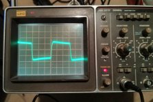
I have just put the scope on my no-name SPDIF cable, terminated with 75 ohms. The signal is the SPDIF from the sound card. One div is 0.1 µs. Probe is 10x.
Very useful Vincent, many thanks for trying this, it pretty straightforward then? How would you interpret your result? Although not a perfect sq wave, a good result though?
Eye diagram looks interesting also, I'll read some more..
Thanks chaps, much appreciated.
5.6mhz would be subsonic! Do you perhaps mean 5.6MHz?
Lol, yes, iPhone and tapatalk thinks it knows better though..
")
- Status
- This old topic is closed. If you want to reopen this topic, contact a moderator using the "Report Post" button.
- Home
- Source & Line
- Digital Line Level
- Is measuring square wave on spdif cable possible?