cable carrying digital signal to DAC, like all cables it can couple noise, measure the system and decide if this is a problem. But just referring to a cables DC resistance is simplifying things a bit. Noise depends on the source, the environment and other factors and can be solved by engineering a solution, and if changing the cables DC resistance changes the sound then your system is crap and needs sorting out.
Completly agree, but in the same time a lot of people can hear change in the sound when cable are changed, so what to understood from this....?
Last edited:
perceive, and again this is a sign of very bad design, cables should have no effect on a well engineered system.
Noise, cables and system susceptibility are EMC problems and as such really need a thread of their own and proper engineering to solve the problem, though like you I go for total isolation, downstream I am changing all my equipment to double insulated, to minimise noise and isolate each stage from the last/next.
Noise, cables and system susceptibility are EMC problems and as such really need a thread of their own and proper engineering to solve the problem, though like you I go for total isolation, downstream I am changing all my equipment to double insulated, to minimise noise and isolate each stage from the last/next.
1x probe is useless at high source impedances and/or moderately high frequencies...
Scope probe cable impedance is 1 Mohm to match scope input impedance of
1 Mohm in the 1X mode. With a 1Mohm source impedance driving this combination
3db BW easily reaches 100's of Mhz. This is not a piece of wire with just capacitance but a transmission line. Coax can easily carry signals in the Ghz range when properly terminated at characteristic impedance.
Wow! Where can I buy some of this 1M characteristic impedance cable? It must have an incredibly tiny inner core.Art M said:Scope probe cable impedance is 1 Mohm to match scope input impedance of
1 Mohm in the 1X mode.
Scope probe cable impedance is 1 Mohm to match scope input impedance of 1 Mohm in the 1X mode.
You are wrong! The oscilloscope probe cable are not 1MΩ.
Cable characteristic impedance is likely to be 50 ohms for the probe. Load on the far end will be 1M. For circuits below a dozen or so MHz, to a good approximation you can think of the probe as being roughly 1M || 150pF.
When it is used with 1MΩ input impedance, in fact, the oscilloscope work in unmatched impedance. The 1MΩ impedance it is used ONLY to adapt with the 10x (100x....) passive probe.
The 10x probe are designed to not influence the measured point and usually have the input impedance 10MΩ/10p.
The probe cable usually have the central wire with a very high resistance (for example the LeCroy 10x probe cable has 200Ω/m resistance, the same is with Tektronix probe). This high resistance for central wire it is necessary for damping any ringing that can occur because of unmatched coupling.
The active probe (usually) have 50Ω output impedance and if it is (usually it is) designed for special types of scopes, the scope it is switched automatically to 50Ω input impedance.
Last edited:
perceive, and again this is a sign of very bad design, cables should have no effect on a well engineered system.
Noise, cables and system susceptibility are EMC problems and as such really need a thread of their own and proper engineering to solve the problem, though like you I go for total isolation, downstream I am changing all my equipment to double insulated, to minimise noise and isolate each stage from the last/next.
We hear the difference between good and bad design. But what is the perfect design, which makes all the differences inaudible?
Is a transformer balanced output to an unbalanced coaxial line perfect? I do not think so and I prefer balanced AES/EBU.
And I agree, cables should not be audible, but sometimes it is.
As long as we have to deal with the compromises, we will also hear some small differences and these can not always be derived from a measurement.
Everything is analog, also the transmission of digital signals.
Really digital is only the pattern which we use for the description and processing of the analog world.
As long as we have to deal with the compromises, we will also hear some small differences and these can not always be derived from a measurement.
But often we also think we hear differences, but those differences disappear when listening under controlled, double-blind listening conditions.
Yes but only at the low level, it is a discipline on its own, it is about two levels, not an infinitely variable signal, and ensuring that the data transferred by those two levels is transmitted error free around the circuitry.
NOPE, as I said write a thesis you will get recognition...
The square wave represents the bits that will cause the receiver to switch at a certain level, that's it the wave does not exist in any form after that, if what you say is true, where are the technical documents where is the research.
Please provide some proof of this world shaking claim.
Digital to analogue basic conversion is the same what ever the circuit or DAC device used.
Yes, it's the digital value, the stream of one's and zero's that determines the sound. Not the voltage amplitude, not the shape.
If a certain cable sounds 'more bright', the cable has to magically replace some zero's with one's and vice versa, in such a way that the error correction mechanism is fooled, so it has to also replace the corresponding bits in the parity- and reed-solomon correction codes to make the error invisible.
Then it has to know which bits to fudge in such a way that it only affects the data that encodes for the higher audio frequencies, and on and on.
That's not a cable, that's a supercomputer!
Jan
Hi all, this is very interesting for me, even though it is beyond my knowledge level. Do continue as it is a good discussion.
My thought's are that while it may be possible for me to view the sq wave, it is not as straightforward as I'd hoped and if an accurate result were seen on the scope, unless that wave was perfect, what part of the imperfection is caused by the cable? In an ideal world, one would connect a signal generator to the scope without cables to compare the real output against the cables output. The transport used for cd reading is considered to be jitter free up to very high frequency, 500 MHz I believe. I could just say well, it sounds very very good to my ears so lets settle on the current cable and get on with enjoying fine music, but I like to see and learn along the way, and that is where you guys are a great help, so many thanks for all the contributions so far..
My thought's are that while it may be possible for me to view the sq wave, it is not as straightforward as I'd hoped and if an accurate result were seen on the scope, unless that wave was perfect, what part of the imperfection is caused by the cable? In an ideal world, one would connect a signal generator to the scope without cables to compare the real output against the cables output. The transport used for cd reading is considered to be jitter free up to very high frequency, 500 MHz I believe. I could just say well, it sounds very very good to my ears so lets settle on the current cable and get on with enjoying fine music, but I like to see and learn along the way, and that is where you guys are a great help, so many thanks for all the contributions so far..
In an ideal world, one would connect a signal generator to the scope without cables to compare the real output against the cables output.
Again, the eye diagram is a better test, but what you really want to test is the effect of the cable on the whole chain. Who cares how the wave that comes out of the cable looks like, if it gets translated to the right data by the receiver anyway?
Thus, what you should do is to have a recoded digital test signal, and measure at the output of the DAC.
Julf said:So you have been using the same DAC for years?
Guilty as charged.
See, DAC is not a problem, bigger problem is wife. I have been using the same wife for more than 2 decades 😀
Julf said:Who cares how the wave that comes out of the cable looks like, if it gets translated to the right data by the receiver anyway?
Yes, correct.
See, data is not a problem, time is. Wave will be translated to the right data, but with wrong timming.
marce said:NOPE, as I said write a thesis you will get recognition...
No, I don't need recognition or Nobel prize. Just repeating what more clever guys found a long ago.
If only 0 and 1 matters in S/PDIF and everything sounds the same, then whole research on jitter subject is a hoax?
All years of research from Malcolm Hawksford, Chris Dunn and other smart guys are just waste of time?
My proposal:
Use BNC T connector to connect your scope between S/PDIF source (CD player, streamer,...) and your DAC.
Let the music play, than start messing with signal. Wrong termination, low-pass filter,.....use your imagination.
Listen to the music and observe waveform signal.
Last edited:
Paul S, have a look at the links #33, it comes under the heading signal integrity.
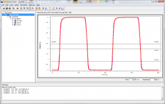
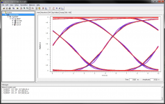
Its not just the cable, there can be numerous mismatches. The attached pdf shows a view of a signal from the point of view of signal integrity (this is taken from a real layout, but I can also model cables, off board connectors, and SCOPE PROBE LOADING) playing with this I can feed signals into the line and look at the resultant waveforms and eye diagrams at various points, I can also do scenarios where I can try different termination schemes, or if possible alter the drive characteristics of the transmitter (this data is stored in an IBIS file).
The resultant simulations can be graphically displayed as shown in the two .png files.
We use this stuff regularly because we do high speed layouts with DDR memory, gigabit Ethernet and other critical digital interfaces.
A few years ago I did set up some sims for SPDif but I think they got lost when a PC went down, if I get time I will do some more, but you do need IBIS data for the driving and receiving devices. (I hope to run some SIMs along with another thread looking at terminations on cables).
So I can simulate an interface, route it to the best sim, and then check the layout with the simulation tools.
playing with stuff like this every day is why I am sure that there is no CORELATION between what a square wave looks like and the resulting analogue if it is going through a convertor...
Attachments
Hi all, this is very interesting for me, even though it is beyond my knowledge level. Do continue as it is a good discussion.
My thought's are that while it may be possible for me to view the sq wave, it is not as straightforward as I'd hoped and if an accurate result were seen on the scope, unless that wave was perfect, what part of the imperfection is caused by the cable? In an ideal world, one would connect a signal generator to the scope without cables to compare the real output against the cables output. The transport used for cd reading is considered to be jitter free up to very high frequency, 500 MHz I believe. I could just say well, it sounds very very good to my ears so lets settle on the current cable and get on with enjoying fine music, but I like to see and learn along the way, and that is where you guys are a great help, so many thanks for all the contributions so far..
OK, did you get the point that when you specify a jitter-free DAC, the cable cannot make any audible difference?
So if the DAC reads in a jittered signal and reads it out with it's own jitter free clock, you're home free.
Jan
Last edited:
No, I don't need recognition or Nobel prize. Just repeating what more clever guys found a long ago.
If only 0 and 1 matters in S/PDIF and everything sounds the same, then whole research on jitter subject is a hoax?
All years of research from Malcolm Hawksford, Chris Dunn and other smart guys are just waste of time?
You said you could tell from the waveform, do not try and twist things I have mentioned eye diagrams, you stated that looking at the digital waveform will tell you how the resultant sound field will be.
If you wanna learn about this, again look at the stuff by the people mentioned in post #33 we are talking signal integrity.
All years of research from Malcolm Hawksford, Chris Dunn and other smart guys are just waste of time?[/
Why are you booing with this sort of comment, there has been lots of work done on jitter, and can be more critical on some high speed analogue/digital designs, though those two are audio based, there is information out there from a broader realm.
- Home
- Source & Line
- Digital Line Level
- Is measuring square wave on spdif cable possible?