Looking for help with the volume of my box

Can someone help me out with the volume of it. Thinking of putting my x-12 in it for a minute if the numbers are close enough
29,5 depth (tall) x15x15
The front for the sub is recessed from the top 2.5 “
The ports are 3.5-3.5-4.5 triangles and they are 23.5 “ deep and there are 4 of them
The face where the sub fits is 2.3/4 from the top .
Everything is 3/4.”
Any thoughts? Ideas? Anyone know who made this? It is very heavy

Attachments

  • IMG_3579.jpeg
    IMG_3579.jpeg
    946.1 KB · Views: 19
  • IMG_3577.png
    IMG_3577.png
    2.8 MB · Views: 12

Daphile - Audiophile Music Server & Player OS

Call for testers!

Daphile is an audiophile class music server & player OS – targeted to dedicated headless PC.

Features

  • Headless music server OS
  • Bitperfect and gapless playback of common audio formats up to 192kHz/24bit
  • Automatic configuration of music player for each audio device
  • Multiplayer support (eg. multiple USB DACs)
  • CD ripping with automatic metadata tagging and cover art
  • Supports external file servers as music source (CIFS, NFS, sshfs & ftp)
  • Easy configuration and installation through the web interface
  • WiFi hotspot support (if compatible hardware exists)
  • Software update via web interface
  • Whole system image ISO-file is below 200MB
Daphile is based on the open source Squeezebox Server, SqueezePlay and Linux.

Get more info and downloads at www.daphile.com.

Any feedback is warmly welcomed!

Portable Battery Powered MEH Build

Need/Use Case: I’ve always wanted a decent bluetooth speaker that I could carry when traveling/hiking/camping/etc. but could never find one that really provided a quality listening experience. Most of the larger manufacturers with bluetooth devices seem to be dubious with their ratings and make speakers that appeal to the mass market with little regard to any sort of controlled directivity (not that omni is necessarily a bad thing when it comes to BT speakers).
In addition to this, I run a sound system for small-medium sized events and have been looking for a no-frills fill box that I can throw in a corner and feed a signal to without having to worry about it, so the appeal of a battery powered “set it and go” box is high for me.

Background: I’ve had a fascination with multiple entry horns over the last year or so having prototyped a few larger format MEHs at this point. If you know anything about MEHs, there are some considerations regarding the size, flare rate, and horn profile to achieve what they do. Going small with a MEH means you do lose out on some of these benefits if you plan to do a full-range build.
However, the primary guiding reason of this speaker’s arrangement is not necessarily to benefit from hornloading the 6.5” woofers, but to offer a highly compact arrangement that wouldn’t be possible with a flat baffle. As an additional benefit this places the acoustic centers of the drivers very closely and provides a good directivity match between the woofers and compression driver, despite the steep crossover. What it doesn’t do is give a substantial sensitivity boost/impedance match to the woofers that you would get from a larger conical MEH.

Build Requirements: I set out to design a speaker that would attempt to hit these metrics:
  • Full range with at least 100dB output down to 50Hz
  • Wide 60x90 pattern with well controlled directivity in both horizontal and vertical axes
  • Highly portable (<15 LBS and <25 liters)
  • At least 8 hours battery life


The Design

Acknowledging that I wasn't constrained by a straight wall conical horn, I opted to utilize Ath to design a waveguide that would provide a more uniform wavefront than would be possible with a pyramid shaped horn. For this reason, I’m hesitant to call it a horn and lean more towards a waveguide (I’m loosely defining this based on my understanding of Geddes’ classification).
For components, I opted towards using the new B&C DH350 compression driver, two 6NDL38 6.5” woofers, and two Scanspeak SB16PFCR-00 passive radiators (ports were out of the question due to the small enclosure size). This blend of components lends itself nicely to a crossover point somewhere in the 1.0-1.2kHz region, so that is what I targeted in Ath/Hornresp.
To achieve that, there was a good deal of fine tuning/tweaking the models in Ath/Hornresp. The basic idea was to really nail the directivity/impedance curve in Ath, then (loosely) translate that profile into Hornresp so that I could leverage the MEH wizard to integrate the woofers and find the point at which they could meet the CD.
Knowing that my crossover would be somewhere in the 1-1.2kHz area, I then sized out and placed the woofer taps in Fusion along the corners of the horn where the centroid of the taps is about ¼ wavelength @xo from the CD exit. I then modeled a flange for mounting the woofers leaving a flat area open so that I could come in later on and add cone fillers if needed.
AD_4nXfTx_utr6lzkPJD_XaleEssRG7xRrKjfpLjH3WbAnQioAx7lpiZOAclqbSkMmwTTRQeS65O1dFdRw5ECj7H6dH60SaOq04AOly5aelizO2DMfns17UZfjH5vuL_X0nBhaQZ7b6Q-YqpJRfV_pCJ_aGy-Iwe
AD_4nXelEPTXIxSfnMvLMpKA0u_fkYVb5-HtRIFXqY4wU4qnaLUeQzWTY-2A73eyURfYvrywr8KZhvqIVilhSupWSlwUxHxbvKQie6Hk9tTG8UuqytwGBnZgjfdGPYWY3HmOxIAY8cQQAF47K_wzjj5513DkEENK
AD_4nXfxOw2_pzBMLhUa7ndgLhlOVb_MDTFafIRPfDkS5aRcrk2FwwGzenBD3gNzNqWfX79rlkyehVzJrJhMg7RXun0Cvyi1ts9x_kZ_hcR2UltQMmX6oDhaau1l0YN-58IWwesvh5iuMf6uaNXbqBB9t8xH6bcr

My 3D printer bed isn’t large, so the model is split into 3 pieces - a left and right half with a throat adapter. I used 2 part clear epoxy to join the halves together. The woofer mounting nuts are heat-set M4 inserts.
AD_4nXfxhL0xoozJoBsGZEWUEqLVxaNCFDYitR1x-duyola4RyhbXOzK7-vUUVZnsk8ZtjDZsNP0NBjZ4srCAko5sYmZzl9mMFS9PkYp49Q0dunmfpp4-SMbvjWLIVMbRJ91444Vy4dIGktzJmGHcfEEtV1ngRqJ
AD_4nXejQxoMs6oi2yPlY8HsJ62wOy7CZvfaA1O1SKepoW2zcew3EHfV0U5f9SK7Ku_hxsoSIIO-7sxzi7JqUvRlpCcuNjFyWll7XltyZMjxICkb-pE2gbiupmNmiY0qyMvYgqdwy8Wa_rzQ3EzBcVIXNBJxkfr_

Because of the proximity of the drivers, the 2 M4 fasteners holding the compression driver in may be hard to reach. I used a stubby hex drive to get to them when installed into the enclosure.
AD_4nXf4AP1IuXgfVEARqbZX3C8bM6RzjdoTEVp_B8-dRGux6QnZV1M7ZzKzDhpEsPlj9cjrBtFJJagCPaZaLZ54QYUlecAgX1UzFaMtmcPeUQbcFQswDqdsyW7j1h92LUZ50QMRr0npwvrlvLpzxEa0PT2FjWnQ
AD_4nXcSqptPUWc4MG-3IkKUPMXUF07maR1tigdXLf3AyCufTPC3mTk7ziZMJLnX1kzMdk-tN4uehKzxSdrLT2PPgBIwnTJD6h-DBInTmM5KtdCU4P8YGHYqmJoeV1VPdckqOwnsAiDUskKLfpeynfqrEJRiVfVE

The enclosure is a simple hexagonal shaped box made from 12MM birch plywood with about a 15 liter volume after accounting for the displacement of the horn/drivers.
AD_4nXcOXImuJF8jvIyZj77UwBl9hD_9DlwiK_OGtVjWOS-rqxjRhJT4GU5IH2GcWl-eIUg2H-xG0XMvz8jfUhK-I6O9mVAPhuFSN8VSpQJO8xY729BYMVEP9F-AeWR5XIZ2aNAAS0_eScqfM_4JVTkzVj44r18f
AD_4nXdDIhRlUWpIyUwyni9B7qh-OzQPYbxBdP5U03xVHdNTIPhDBI1GgtZ4o-GmqzGcdnbMz7ef7nCNw_moRZXSkSKatyx7Kg_7GRzW35WhUhNzA6QEBS2VrR9zKI8R45zqD5r5oGtIjFQgspkCDSeSN4UO55o

Unfortunately I misjudged the amount of clearance I'd need for the passive radiators, so they do butt up against the rear of the woofers when installed. If I do another box, I’m going to add a couple extra mm clearance there. The good news is that there is a hole in the basket of the passive radiators that lines up perfectly with the 6NDL38’s pole vent, so I don’t anticipate any overheating issues there.
AD_4nXcUmjjfadt5lZxBe3AC-BmZmVB4Gloyaj2HR5pxxGEMAafReAL0Iw4G59eFGKVjHtUrR7UXDk2sIS1EE-JOhYyrCLF-Kicyu5YAEztFQAx4tIaMViqhMZnk0BVH4__ujTUcpwj76q_Ln8xRaXBYgFBvZtyJ

During the initial testing I taped the front of the waveguide to the enclosure. This went about as expected, but I was at least able to get the data I needed. I use an outdoor ground plane measurement setup according to this guide from Scott Hinson. Measuring with a Dayton audio UMM-6 with a 20 cycle FDW applied at 1 meter (2 meters for off-axis). 30°C at 72% humidity.

For this first prototype, I wanted to validate the Abec/Hornresp model and check physical fitment - wasn’t going for a final rendition. The thought was to build the initial prototype and gradually add cone filler until I achieved the desired woofer response. For the most part, this was a success, but for whatever reason there was a secondary peak in the woofer response that I hadn’t anticipated. I’m going to consider my failure to anticipate this a happy accident, because it meant that the woofers conveniently worked out perfectly to meet the compression driver on the first try. If you have any insight/theories into why that secondary peak might exist, I’d love to hear.
1722394819005.png

Barring that, the unfiltered responses of both drivers overlaid looks like this.
AD_4nXcjpAonEBnnBKeOQQUEX7jvn3Ca-s9n3b1Ef3SbTMqw8GiRpEgnE-wDqQY14bNaqfY4URBjaXGiwthbsi9xD_w-EHBftkmlYHu7uQkYB5rR5ePUlAZ0DZ8BqJkI5ooEmFvSXdHIClLeEet1RPJlRsTxw6Wn


For the woofers, I opted for a 1st order 80Hz LPF to flatten out the response, which got me 80% of the way to where I needed to be. After applying some corrective EQ, I was able to get a solid response from 60Hz-16kHz. I’m applying a 4th order 45Hz HPF to protect from overexcursion. After generating the spinorama I realized I probably could have done more on the EQ front to correct the 500-2k region, but I’m happy enough with it and don’t really wanna do 36 more sweeps just to make a squiggly line less squiggly.
AD_4nXcfO0glRWOj19jSmLX686jyYnVRYp4qtF53Y1LN7IR1nlL3m_EJOlSzaRAMjAQZQf8O_X-I_pWLZ4J76IPAw8e56f2U64CUSheA0sx2Zgj6JPXXH-1A1DxQI4VFva6_y3FfuVS1iB40i40Dps87too1WJo

Distortion as measured with stepped sine tones:
AD_4nXetDLzEtuvPfSmYfay_GEvAj-YypTT6070Hz-jQaWXzHrNQh2Nsu1uXyHXhnCKIoKvHYOmk0My-zburG8mOIfIjd3AfRqMQmLj40zEAxziZ_kREyEo3hI2gRmpE6Pm5vpUiqArfkWIKHQXuDk1s5c3APaA
AD_4nXe0LWPZ9WoA_-XkwhTho-iuD_iUGm-2WTDp3f21_NPWPPxt_hIJwVhJDFCJ_HI_3Dpy7LbbnCHbEwCBXk9XT6GmuA33wT11ZIQ7WbRaNAkf33JlftiS-z2Jy3e7hPURSP8u25dkYEZpsHVMmbjCBaru1eA

Group Delay:
AD_4nXdSQ2RCaI_Xxb-oIG_vqWfJJs0_9k1x6z9UCgB70nJ47GRAGT-sUR-n8UJ2y18tlU30Cb37wJlzqsLxJWTTYDzhie9DOIVeO8cUFSI-qlnt6YYwElwKT-PTWoQa_enfaXrK6sXicVVJkWiBq47sSEkvaVAX

And finally polars (normalized on axis):
AD_4nXfzMD4bAsTZ5pqrr3qwxAFCfzYyxoGL2kcTZA8LLuB3C2UVEkMkIrYnUHB64dRUA8nVlfGOe6w_jiq-Ib-vEZk5uTdTNCIlILGDpQW3lahRb3VSYWDO9FNGrlOB_64M9tHIVMe-fu3Gm3iCzZHOOxE-Z6XB

AD_4nXcxCfhfBF6MwpLzwq05NGUId_9MXWhCUmfroJ_NHKCliFLOLvZM9trBs_3hycYy6zt_wn2R0lDZ6SE4MX3tZYP_25EgpatkaGaOLNJoaYml5iN8sdfJkbD_JyVsW4JdQ16PWykCKmHvEQbmAIk9w85l0pqx

Given these results, I decided to go ahead and finish out this prototype. There’s some details in the physical construction of the box I might make in a future version, but overall I was quite happy with the performance. I chose a Dayton Audio KABD-4100 amplifier paired with one of their 6 cell 18650 BMS boards, mostly due to availability and balance of features. One of the outputs was left unplugged, so it's not the most efficient setup but I found it works quite well for the price. The sigmastudio file is provided in the zip file.

Regarding the enclosure, whatever you build make certain it's well sealed. You may want to modify the flange on the waveguide for a cleaner mount. These little drivers move a lot of air and I spent the better part of an afternoon working out caulking/gaskets to fully take care of air leaks.
AD_4nXeuJh4gR5iB2KmQQxblx5uUT4znmI5GifCCKtCHRB8S1keXMc7S_P_IfcomsEsiMD3YP9EPPulHi0VFXGrol8IYkMJbBsM75158jpFAbM8_vqMKHt4HaRfzS1gSG69cU8Xogi7ClFKZx6bd0DgWbZ3gkRUs
AD_4nXfBsht_PanDeHMELFZnb_i1XWSnQiQaGDIO58tEgKIcrmO2Wsn9xpa7RcTS5KKH9rKxxonp4ofCU3Bo5dJ9uXKewUSb7PEjqz9tsweAd6dPMjO4PzexGQF1DcSNMko0CPasRtMGt8vJ0fxpPzfqgqfgaViH
AD_4nXe8xhaAltWFD-L21V2LSgg_cDSj3Exwi78aNrm4WlO29nyUwv1KFMKEPeb41b2XuHRDNzjG067X1jHl6tXDrGYpAEQMQQIkv-wRnlrtGJzbL4EgDDYKeyza019cZDJ5oVUT5_Pktx8FwRFoWvA_zOAfFeFK
AD_4nXdDq__MfISEEpNEaUY90HjPwqGIL-JNsaWHCS8vWxaZhhrRmdc0FtsRpkRNNXdCau_mvvd-gYp6HwB2TVybw_lcQVim4qg8KTgClAsQwq-bUwIFrrXkARD6DmulNOT2o85Tl7p5A-JPg8MgvgjZstTnxXJu
(I've since added a Neutrik combo XLR jack to the rear)


Specs
  • Frequency Response: 60-16kHz (+-2dB)
  • Coverage: 75Hx60V
  • Maximum SPL: 106dB (about where the 6NDL38s and PRs reach xmax - can reach higher if you HPF at 80Hz.)
  • Battery Life: Subjectively well over 8 hours, but I’ll be doing an M-noise stress test later at some point to get a real validated runtime number.
  • Weight: 14.9lbs (6.75kg)
  • Outer Dimensions: 18.5” wide x 10.2” deep x 7.9” tall (47x26x20cm)
  • Internal Volume: about 15 liters
  • Components:
    • 2x B&C 6NDL38 Woofers
    • 1x B&C DH350 Compression Driver
    • 1x Dayton Audio KABD-4100
    • 1x Dayton Audio LBB-6S
    • 6x Samsung 35E 18650 cells
    • 2x Scanspeak SB16PFCR-00
Download the .STLs and SigmaStudio file here.

Compromises: These are the areas that I’ve identified as weaknesses in this build or areas for improvement.
  • Coverage is a bit narrower than I would have liked it to be. I think I need to refine my Ath skills a bit more since this didn’t necessarily match the polars I generated in ABEC.
  • The steep crossover slopes may not be ideal for some listeners and introduce a small amount of group delay (about 1.3ms at 1200Hz.) This could probably be corrected with FIR.
  • The DH350 breaks up at around 16kHz, so don’t expect full extension up to 20kHz
  • Distortion is higher than I’d like it to be on the low end - no doubt due to nonlinearities with the passive radiators. They’re cheap - buy better ones if you can. Also - you should be able to achieve much better bass performance by increasing the box size by about 25%, so if space isn’t an issue that should be considered.
  • Subjectively, the DH350 lacks a sort of upper midrange clarity that I’ve heard with other (larger) compression drivers. I’d wager this is due to some diaphragm resonances, but haven’t measured it. I’d recommend buying one to prototype with other horns/waveguides to assess this yourself before determining if this build is for you.

How to get a really good measurement of a sharp square wave on a scope?

I'm developing a bunch of high speed digital electronics (DAC filters etc) and I'm struggling to get a good reading of the high frequency signals. The problem is that the edges are intentionally extremely fast and very square. It seems to be causing a lot of ringing in the scope readings and they are appearing anything but square! Any ideas how I can improve on this? I get the same effect even when measuring the raw clock signal straight out of a single CMOS NAND gate, so it should be pretty clean (and yes, the circuit board design is good - ground planes, bypass caps etc are all as they should be - I'm confident it's a measurement issue not a circuit issue!)
I'm using a Tektronix 500MHz scope (TDS754 so quite old, but pretty good) with a 1GHz passive probe.

Tiny Passive Radiators?

I'm working on a powered speaker that will fit in a guitar pedal enclosure (66mm x 121mm x 40mm). I'm taking inspiration from the many small bluetooth speakers that provide surprising bass for their size. I realize there's probably DSP at work, but I also often see passive radiators as well. For example attached is a photo of a small guitar amp called the Spark Go which measures 163.7 x 75.6 x 8.6 mm (6.44 x 2.98 x 0.34 in).

I haven't been able to find any reviews or even suppliers for radiators this small. Does anyone know of any, particularly European suppliers?

SparkGOBlackgrid03.jpg.webp

I have a Garrard Model T motor which has some wires in one of the coils broken. Upgrade? Fix? Replace? or hire someone to fix it?

5-7 wires are broken on one of the two coils
Could I get it repaired?
How much?
Could I repair it easily?
Is there a better motor which would drop in?
Does anyone repair them for aa good price?
How much would a model t motor cost?
Does anyone have one?
A Compatible one?
thanks

I love all you good hifi lovers

Pie in the Sky - air jet rotation?

I know of air bearings etc however it's occurred to me that:
a) the sides of a large platter are smooth to minimise variations in speed.
b) motors or any pulse of energy causes variations in speed.
c) that multiple air jets using the friction of the air against the edge of the platter can rotate - a case of 'contactless' air propulsion where the air is regulated to prevent any variation in velocity.

This would then have a constant speed, with low variability. Multiple jets are likely to be needed to provide enough force to overcome the needle-record and bearing friction.

Just wondered if this has been attempted previously?

failed capacitor?

I've got an Allo Shanti dual power supply with a 3amp (dirty) and 1amp (clean) side. The Allo Digione Signature has been giving me grief, and I thought it might be this power supply. I opened up and found some oily residue in there that should not be in there. It's stored pretty far behind stuff on the third shelf down of the hifi rack. I did some poking around, and it's likely a failed capacitor, but I'd love some second opinions before I buy parts and start down this rabbit hole. Any advice or wisdom? thanks!

In one of the pics, you can see my finger smudge on the pcb for reference.

Attachments

  • PXL_20250624_233225161_edited.jpg
    PXL_20250624_233225161_edited.jpg
    419 KB · Views: 62
  • PXL_20250624_233327353.jpg
    PXL_20250624_233327353.jpg
    612.3 KB · Views: 64
  • PXL_20250624_233318509.jpg
    PXL_20250624_233318509.jpg
    432.4 KB · Views: 63
  • PXL_20250624_233312368.MP.jpg
    PXL_20250624_233312368.MP.jpg
    551.4 KB · Views: 62
  • PXL_20250624_233235869.jpg
    PXL_20250624_233235869.jpg
    707.1 KB · Views: 59
  • PXL_20250624_233229652.jpg
    PXL_20250624_233229652.jpg
    456 KB · Views: 62

Most basic Ian Canada setup

Hi, stumbled upon this forum when searching for a new dac hat for pi. Maybe I am in the wrong place but am only looking for a rough opinion so I know if investigating further is worth it.

Was initially looking for an Allo Boss but found this gear from Ian Canada that looks promising. Somewhat hard to know exactly what I need to build the first and basic version of a dac with this. Would the enclosed 3 parts (and pi) be enough to have it functioning in a good way? Like the fact that it could be upgraded further on.

And second, and most important, would this be a "substantial" sound improvement over the Allo Boss if using average hifi gear (Hegel H80/Q Acou. 3020i)?

IC DAC.jpg

What is equal loudness volume control.

Hi,
I am seeing volume control potentiometers on ali express with few resistors and capacitors, for equalizing loudness for different frequencies at lower volumes. How does these work, does these boost low and attenuate highs more at lower volume levels, are any fixed values of resistors and capacitors used to achieve this. I suppose this works with stepper potentiometer or also with stepless?

https://www.aliexpress.com/item/1005003983780875.html

Iron Pre Essentials Kits For The DIYA Store - Register Your Interest

The Iron Pre is now listed in the diyAudio store for anyone to purchase.

Until the 'Build Guide / Build Thread' is created, this post will contain all current schematics and notes for the Iron Pre sold through the diyAudio store. Check back frequently to ensure you have the latest files.

Sep 14 2023 - Below is what you're waiting for! See some awesome information and help from 6L6 on the SE build. A new thread and the guide using the web interface will be posted ... soon. Post #2291

1694728999259.png


Background


Hello Happy DIYers / Greedy Boyz!

I am thrilled to announce that Zen Mod's Iron Pre essentials kits will be offered in the DIYAudio store. This is not a group buy. You can learn more about the project in the thread linked below.

https://www.diyaudio.com/community/threads/whats-wrong-with-the-kiss-boy.293169/

Highlights include matched Toshiba JFETs from Nelson Pass and high-nickel CineMag transformers. 6L6 has volunteered to post one of his incredible build guides also.

If you're a Smiths fan, you may ask, How Soon Is Now? They should be available for order before the end of the year. At this time, we have enough parts sourced for 100 SE and 50 balanced kits.

The next obvious question is, how much? Costing is not final yet, but the goal is $100 for the SE kits and $125 for the balanced kits; a tremendous bargain. We have contingencies for all the parts, and we hope that this will be a permanent addition to the store. However, for now, we can only promise what we've got. Get 'em while you can.

Click the link below to see what will be included in the kit, answer a few questions about what you might like to see in the future, and get on the list.

Note - The n-channel JFETs will be 2SK370.

Quick and Dirty Startup Process

This happens after: the boards are stuffed, the AC supply is verified and connected properly, and I/O has been connected. Nothing needs to be shorted. Note the additional step for the V4 SMD version.

  1. Set V+ and V-

    Adjust P1 and P2 for each board until
    V+ is +15V0 and V- is -15V0

    GND, V+ and V- pads are clearly marked on PCBs.
    Do not move forward if you cannot adjust the voltages to within 0V1 or if the voltage seems unstable.


  2. For V4 SMD Only- Set current through JFETs
    • Set DMM to DCmV.
    • Place probes across R34 and R37 for SE or R40 and 41 for Balanced. You can also use square pads / test points near resistors.
    • Turn P4 and P6 respectively until DMM reads 14mV +- 0.05mV - See schematic.
  3. Null DC offset
    • SE
      • No jumper caps in place for JP1 or JP2
      • Measure at center pin of JP1 and JP2 NOT between those two pins*
      • Turn P3 / P4 (V3 and earlier) or P3 / P5 (V4 SMD) respectively until voltage shows 0V +- 5mV
      • Cap the jumpers for your choice of gain.
    • Balanced
      • No jumper caps on JP+ or JP-
      • Measure at pin 1 of JP+ and JP- NOT between those two pins*
      • Turn P3 / P4 (V3 and earlier) or P3 / P5 (V4 SMD) respectively until voltage shows 0V +- 5mV
      • Cap the jumpers.
Do not move forward if you cannot null the offsets to less than +- 5mV
3. Sing Happy Tunes
*Measure at a particular point => Measure between that point and GND.
Updates

4-May 2023

Edited 7-Aug 2023.
All in-line photos have been removed. Please see attached files for all documentation.

5-May 2023

Updated Single-Ended BoM to correct 330R part notations in the gain stage to R28 and R29.

Attached are the Bill of Materials / Parts Lists - Note File Names for Balanced and SE

26 - May 2023

Updated SE and Balanced Bill of Materials to indicate that snubber components should not be installed.

Balanced BoM Filename - BOM_Store_Iron_Pre_Balanced_Dist_v5.pdf
SE BoM Filename - BOM_Store_Iron_Pre_SE_Dist_v5.pdf

27 - May 2023

Updated SE and Balanced Bill of Materials to correct and clearly note which diodes should be installed for input switching.

Balanced BoM Filename - BOM_Store_Iron_Pre_Balanced_Dist_v6.pdf
SE BoM Filename - BOM_Store_Iron_Pre_SE_Dist_v6.pdf

1 - June 2023

Note - No changes required. However, the packing lists some of you will receive may note LM336-5.0. That was a typo; apologies. The correct parts (as supplied and noted in the BoM) are LM336-2.5.

Removed the link to sign up indicating interest in kits. Those currently on the list will get first priority for the next round of kits. After that, they will be sold through the normal process through the store.

6 - June 2023

There are two gorgeous prototype chassis available; one designed specifically for SE, and one for Balanced. You can find some details in post #431. The depth for both chassis is 280mm. There is additional information sprinkled throughout the thread re: acceptable sizes and some potential part numbers for IECs, input / outputs etc. along with pictures of some examples. Please search first before asking chassis questions, and I'd recommend using the latest posts' information. Again, they are prototype chassis, and anything could change at any time until the design is finalized. The best source of information re: the chassis is directly from Modushop until they are sold in the diyAudio store. Timing TBD.

8 - June 2023

Added parts placement and pcb layouts for those interested.

30 - June 2023

V7 - Minor Updates to BoMs. QTY added. Ensure to check quantity per board against the quantity you need for your project. Added links to a popular online website to show examples of parts that will work for the connection between the main boards and the twister boards for input selection / LED power etc. Added generic descriptions for those that would prefer to select their own parts.

1 - July 2023

V8 - Minor Updates to BoMs. Added heatsinks for M3 if 12V relays are used.

7 - Aug 2023

I'm excited to say that more kits will be available very soon for 'round 2'. Continue checking this post (as always) and the thread overall for up to the minute updates.

In his graciousness, ZM has made some minor running changes. Changes are:

  • Updated transformer snubber circuit.
  • Easier positioning / mounting of the CineMag transformers in some situations.
  • Changes to allow easier use of some logic circuits for input switching.

Boards that include the changes will note "2023" vs. "2021" on the silkscreen. The Twister board accompanying the 2023 boards notes V.3. Both 2021 and 2023 boards are included with 'round 2'. You cannot choose which you will receive, and you will not know which you will receive until they arrive. Do not fret if you get a kit with 2021 boards. If you need to use a particular type logic solution, there is a very easy modification previously noted in the thread, and the snubber is not necessary. The changes made were a kindness from ZM, but all 2021 boards can be made to function just like 2023 boards with a few user-tweaks described in the thread.

Note - The attachments have been packaged and note which files to choose for the respective boards. Previous attachments and in-line thumbnails / photos have been removed for clarity. The BoMs have been updated slightly for clarity.

9 - Aug 2023

There is a minor error on the silkscreen for the boards marked Iron Pre SE Zen Mod Labs 2023. The polarity notation for C11 visible when the cap is installed is incorrect. Ignore it.

1691581335126.png


13 - Aug 2023

His Mightiness created two graphics for how to wire standard pots for both SE and Balanced. Attached.

29 - Aug 2023

Minor updates to balanced BoMs. Removed reference to D15.

31 - Aug 2023

Added wiring diagram for AVC for SE. See post #2113 for context.

21 - June 2024

All testing for the Super Mega Deluxe version is complete. Kits will be back in the store 'soon'. :snail:

25 - September 2024

"Soon" is relative. 🙂. SMD kits are on sale. The schematics and files for the Super Mega Deluxe (SMD) have been attached in their appropriately named .zip files. Enjoy your builds.

26 - September 2024

A few people purchased the "completion" kits for the V3 and earlier boards and were wondering if they could be used for the V4 SMD kits. A lot of the parts are identical, but below is what you'll need in addition and to swap a few parts.

For balanced you will need:
4x additional 825R or 820R resistors - I like these Vishay BC 825R
8x 58R or 62R resistors - I like these Vishay BC 62R
4x 1R resistors - I like these Vishay BC 1R
8x 100R trimmers - I like these Bourns 3296 Series 100R Trimmers
4x 1uF film caps with 5mm or 15mm lead spacing - I like these TDK 1.0uF with 15mm Lead Spacing

For SE you will need:
2x additional 825R or 820R resistors - I like these Vishay BC 825R
4x 58R or 62R resistors - I like these Vishay BC 62R
2x 1R resistors - I like these Vishay BC 1R
4x 100R trimmers - I like these Bourns 3296 Series 100R Trimmers
2x 1uF film caps with 5mm or 15mm lead spacing - I like these TDK 1.0uF with 15mm Lead Spacing

27 - September 2024

Some potentially helpful additional parts in post #3784. If people have more helpful suggestions, I can add them.

3 - February 2025

Added diagrams for setting buffer current in V4 builds.

Attachments

  • Iron Pre 2023 v.3 how to pot.png
    Iron Pre 2023 v.3 how to pot.png
    206.6 KB · Views: 2,437
  • Iron Pre SE 2023 v.3 how to pot.png
    Iron Pre SE 2023 v.3 how to pot.png
    221.7 KB · Views: 2,419
  • 2021.zip
    2021.zip
    1.5 MB · Views: 755
  • 2023.zip
    2023.zip
    1.4 MB · Views: 1,159
  • Iron Pre SE 2023 v.3 how to wire AVC.png
    Iron Pre SE 2023 v.3 how to wire AVC.png
    241.3 KB · Views: 2,296
  • Iron Pre Balanced SMD V.4_1.zip
    Iron Pre Balanced SMD V.4_1.zip
    847 KB · Views: 487
  • Iron Pre SE SMD V.4_1.zip
    Iron Pre SE SMD V.4_1.zip
    878.9 KB · Views: 468
  • Iron Pre Balanced V4 Set Buffer Current.jpg
    Iron Pre Balanced V4 Set Buffer Current.jpg
    197.9 KB · Views: 382
  • Iron Pre SE V4 Set Buffer Current.jpg
    Iron Pre SE V4 Set Buffer Current.jpg
    143.3 KB · Views: 420

Volcano Soundsystem - my flight ready mini Disco/DJ rig build

Hello all. I have been trying to get a small soundsystem together for a while, without being able to make much traction on the project. Mainly due to time constraints and a lot of muddle over the config of such a system. I made many plans and acquired a bunch of parts and equipment for the new system, but it has been difficult to find an optimum due to the following requirements

Extremely portable, to flight ready
Weather resistance, some marine environment ability required
A bit of independence ability from fixed power points
Bass heavy sound
Wireless where able
Multizone compatibility
Live mics and instruments ability
Karaoke
The music is classic and modern Bollywood and West Indian

It took a while for me to note that where I needed environmental protection, the gig was smaller and with a much smaller range of inputs. I have decided to make it a pool of gear that I can mix and match for my needs. I have also had to consider some ready rolled gear instead of all DIY to neatly meet the requirements

Speakers
This is where I am trying something different. The JBL BB3 has sufficient output for the smallest gigs that I do. I acquired a Zealot S89, which appears to be similarly built as the BB3 and contains the same Racer8 driver that I have been messing with. The internal speaker setup is 2.1 with the mains section containing tweeter and midbass two-ways. I have been trying this one out over the last few days and the output is tremendous for something this small. The sound is clean and bass is forward and powerful. Battery life is impressive too. From full charge, the unit lasted a night, day and a night before turning itself off. This was at my regular indoor listening levels. Charge time seems good. My laptop USB-C charger works very well. I timed 6hrs charging time with a regular 5v2A charger and the laptop charger was lot faster, but I wasn't home to get the exact number this time

1750093620278.png


1750093818502.png


1750093937836.png


As is, the S89 will be ample for the porch, garage, deck and boat deck parties. No wires to tape up, trip up on, or pack and unpack. This connects to one of the BT TX fobs. This unit will face me as monitors while supplying the bass for the rest of the BT system. For the mains, I have bought two Zealot S97 units. These will face the floor and connect to the second BT TX fob and operate in TWS with each other. The S89 will be either used on the DJ desk or on the floor in the floor play area if I am mixing a baithak crew. This is a stop gap until I have a better solution here. Anyone who followed my Club Sandwich attempt will be familiar with this issue

I have picked up a further Zealot S51 pair to use as desk monitors for when I have the S89 on the floor. I have to get one more BT TX fob to add the console's headphone out to connect to these in TWS. One end of these speakers is designed as a base to stand the speaker up. It also contains a downward firing PR as well as an upward firing PR on the other end. Btw, the other models also contain dual PR units. I have some red stretchy nylon fabric and sew up some drawstring rucksacks for these speakers. They fit will in my booked of 4x 23kg and 4x 7kg luggage allocations. These are 100L heavy-duty duffels except for a couple of hard shells for the electronics in 7kg carry on allocations. The gear doesn't take up all of those bags

In an earlier attempt, I picked up a pair of DS18 Pro-zt69 coaxes. These are quite efficient, and I am considering tapping the tweeter and woofer wires from the S89 to drive the coaxes as active two-ways. I am reasoning that the powerful lil amp and battery inside the S89 will drive the coaxes a lot louder. To this end, I have been preparing a pair of cabs for the coaxes. I have a pair of SBA racer type PR units that may suit these cabs and coaxes too for a 60-70hz tune. At the moment the cabs are sealed types and 11L internal volume each

For external subs, I am considering a PA 18 with 4R+4R DVC and neodymium mag to reduce weight in a custom composite cab. The subwoofer amp inside the S89 sees a 2R load from a very inefficient driver. I hope that I am correct in reasoning that I can get much louder output with an 18 with coils in parallel. Tuned to the same 40Hz or so as the S89, so as not to upset any DSP filters already in use in that

If I am careful with the tapping, I should be able to retain most of the weather resistance of the unit for when it is used as is and with external speakers, I am hoping for much greater output


1750091793396.png


For local use with mains power supply, the external speakers will run off proper class d power amps. These are already acquired too

Experimental stuff
The 18" external sub thing will happen later on. Along with the coaxes, I am also building a cab for my DS18 ZR12.4D driver. This is not quite as huge as the ZXI 12" but still substantial. Will fit in my baggage allocations too for the trip coming up. For this trip, I will AB the Zealots vs the coaxes+ZR12.4D. Won't tamper with the Zealots just yet, so will run the external speakers with class d modules

1750094033838.png


The sources
A Dynabook Protégé for laptop. A Roland DJ-202 as controller and Serato DJ pro with full plugins and expansions bundle. A two into one wireless mic pair for the mic input on the DJ-202. This is my basic source setup for DJ, remix and karaoke

A Yamaha MG12XU console for accommodating more mics and instruments. A further one to one wireless mic pair for vocals from the console. This lot of flight ready sources are topped off with an Akai MPK Mini Mk3 Plus for some keys to complement the Roland TR drums built into the DJ-202

For local use, a Roland JDXI synth and a Roland MX-1 mixer completes the set

I have added two Bluetooth transmitter units to this lot. They are placed on the main and monitor outs of whichever mixer is feeding the PA

Party gear
A fog machine/disco light combo. UV black lights. LED party lights and rope lights. UV reflective backdrops. Projector and screen. Stand for mounting projector and lights

Support gear
Two powerbanks with fold out solar panels. Another pair of smaller powerbanks for the LEDs. USB hub with multiple monitor support. Laptop USB-C charger for the car to top all the things up as backup

I am sure there are some things that I am forgetting to list or missed entirely

  • Poll Poll
Cello Palette Style EQ Design (was High End Tone Control)...

If you where to build a Cello Palette functional clone, what technology do you want?

  • I want a Software Palette, Analogue EQ is SO 20th Century

    Votes: 8 16.7%
  • I want a purely passive EQ to which I want to add my own input buffer and output amplifier (MPPJBTS)

    Votes: 9 18.8%
  • I want a Minimalist discrete EQ using Tubes (ZenEQ derived from the "East German EQ")

    Votes: 15 31.3%
  • I want a Minimalist discrete EQ using Solid State (ZenEQ derived from the "East German EQ")

    Votes: 22 45.8%
  • I want Op-Amp's with parallel and summed bands (e.g. NitePro EQ3D)

    Votes: 5 10.4%
  • I want Baxandall Sections with Op-Amp's connected in series (e.g. Carl_Huff)

    Votes: 3 6.3%

Folks,

At the other thread I noticed interest in what may be called a "functional clone" of the Cello palette. Please review the High End Tone Control thread for background information and the options discussed:

http://www.diyaudio.com/forums/analog-line-level/194119-high-end-tone-control.html

The Palette is best described as a Stereo Mastering EQ designed for easy and intuitive use by non-engineers (most EQ's need operators with at least two degrees and many years of experience to get suitable results). One way to describe the actions of the six controls of the Palette approximately is:

Bass [20Hz]
Drum [120Hz]
Lower Voice [500Hz]
Presence [2Khz]
Rasp [5KHz]
Air [20KHz]

Control ranges are 'weighted' so that any changes for a given rotation in for example the "presence" band are much smaller than the "bass" band, relating directly to the behaviour of the human hearing. The Palette has possibly more adjustment range than is beneficial and due to a number of factors a true clone is jut not a sensible option nor is it necessary.

Here the original:

2467402627_962b6f0058.jpg


In principle we can realise something that follows most of the Palette design brief using any technology we care to apply, so much is established.

However "Vita brevis, ars longa" dictate that we cannot spend time, effort and money on making a Palette functional clone with each and every available technology and then to let everyone choose which design suits them best.

So for starters we set the following outline for the actual EQ function:

Centre frequencies:

20Hz +/- 12 ... 18dB
120Hz +/- 6 ... 9dB
500Hz +/- 3 ... 5.5dB
2KHz +/- 3 ... 5.5dB
5KHz +/- 6 ... 9dB
20KHz +/- 12 ... 18dB

We can make bands somewhat adjustable using switches if desired.

Adjustment range is open to some debate as well.

Controls should be able to use generally available potentiometers but can be implemented also with rotary switches.

If we limit ourselves to 24-Pole switches (actually 23 Poles usable) this gives us +/- 11 positions for boost/cut.

This suggests 0.4dB steps for the innermost bands (so +/- 4.4dB), 0.8dB steps for the intermediate bands (so +/- 8.8dB) and 1.2dB steps for the extreme bands (so +/- 13.2dB).

If these items are agreeable we can proceed to select the electronic circuitry, here is where the poll comes in. If you are interested in this analogue (re)mastering EQ project, please vote in the poll on the technology to be used. the poll is multi-choice to perhaps vote 1st & 2nd choice...

Ciao T

Cambridge Audio azur 640h freezes

My Cambridge Audio Azur 640H won’t start. It gets stuck on the startup screen. I can hear the hard drive spinning up and a fan humming slightly, but nothing else happens. When I connect it to a TV, it shows a blue screen with a black bar at the top—no text. TV output shown in the attachment. Could the hard drive be broken, or is something else wrong?

Attachments

  • Azur 640h.jpg
    Azur 640h.jpg
    527.1 KB · Views: 25

How does this horn/waveguide work?

From https://audiohorn.net/tweeter-waveguide/

1751036702863.png

It looks like a normal phase plug we see in smaller 1 inch voice coil compression drivers with 1 inch throat.
A cloth/silk dome tweeter works in breaks up mode, how can a horn/waveguide produce a plane wave?
Can somebody please explain what is happening? @Patrick Bateman

Thanks and Regards,
WonderfulAudio

What are "Symmetrical Drive" woofers?

I have been on the hunt for some good woofers. In the range of 30-500 hz. I keep coming across something called "symmetrical drive".

Maybe someone can answer these questions:
  • What exactly is it?
  • How does it work?
  • What is its benefit?
  • What brands/lineups use it?
  • Is it more advantageous in one octave over some others? Or is just just plain better?
One thing I have learned in my career is that most things in engineer are a trade off. The only way to overcome the tradeoff is with better technology. I am a fan of metaphors so here is the main one I use when explaining this to lay people:
The dampers in your car affect handling and comfort. You want more handling? You go stiffer, then you lose comfort. You want better comfort? You go softer, you lose handling. That is unless you have better technology like a digressive shock. Better comfort with basically no drawback in handling. The trade is higher cost. Is symmetrical drive this same concept?

As far as I can tell tell, there are only 3 companies that use symmetrical drive. This first is Scanspeak with their revelator and illuminator lines. The other two, allegedly, employ designers that left Scanspeak. SB acoustics with their Satori line and Wavecor with their higher end lineup of woofers.


The final question becomes: Is it worth it?
Lets compare two drivers:

This Wavecor has a regular drive and is $120
1747518633002.png

For $51 more you can get a symmetrical drive.
1747518668976.png


Clearly this isn't a one to one. But I am wondering how much more you get. Is it a huge difference? Or is it just a "nice to have"

For Sale Andrea Mori PPG 22/24MHz clocks, OPA861 x17, DIR9001 x8, Various Trafos

Clearing out some bits and seeing if there is any interest


TWTMC-PPG-XO-22/24 MHz
22. 5792 MHz & 24. 576 MHz Pierce pico gate oscillators pair

SOLD
IMG-20250617-WA0005.jpg

8x DIR9001 SPDIF Receiver chips
€15
IMG-20250617-WA0002.jpg

17x OPA861 Transconductance Amp chips
€18
IMG-20250617-WA0003.jpg

Triad Magnetics VPT12-8330
115Vx2 to 2x6V 100VA Toroid
Wires have been cut shorter, no mounting hardware.
€25
IMG-20250617-WA0006.jpg

Triad Magnetics VPT12-23800
115Vx2 to 2x6V 250VA Toroid
Wires have been cut shorter, no mounting hardware.
€50
IMG-20250617-WA0001.jpg

Triad Magnetics VPS24-5400
115Vx2 to 2x12V 130VA EI core
€25
IMG-20250617-WA0004.jpg

Noratel TA250/18
115Vx2 to 2x18V 125VA Toroid
Wires have been cut shorter, no mounting hardware.
€40
IMG-20250617-WA0007.jpg

Other Ads:

Getting 5V DC from a 7812 output in parallel?

I have this little phono preamp which has an integrated psu, converting 12-0-12 ac coming from a center tapped transformer, to regulated +/-12Vdc with a 7912/7812.

I need a 5Vdc in this chassis as well, so I used a LM2596 DC to DC converter I had lying around which I plugged on output pin of the 7812 and ground, in parallel, the 12Vdc is stepped down to 5Vdc.

I have tested everything and it works fine, the phono preamp seems to do its job and the little ADC on the 5V supply is working fine as well.

Is there any downside to this setup? Should I try to build a psu which will be also fed from the 12-0-12 AC in parallel to convert it to 5V dc without connecting to the phono preamp psu?

Thanks!

2x100W TPA3116D2 (2 chips, each in PBTL)

Hi guys,

Among all the TPA3116D2 hype I've seen many single-chip stereo and mono boards (2x50W or 1x100W) as well as dual-chip 2.1 boards (2x50W + 1x100W).

I don't really need a sub but I'd like to have some extra power for peaks, especially when driving 8ohm speakers. What do you guys think about this board?

2 100W TPA3116 D2 Dual Channel Digital Audio Amplifier Board 12V 24V for Arduino | eBay

Does it look like I can get decent quality or would it be more advisable to get one of the well known boards in the wiki?


Thanks!

For Sale NOS Siemens (RFT) EL-34 Tubes - Matched Quads

I have 4 matched quads of Siemens EL34 tubes, purchased from Roger A. Modjeski and matched on his computer tube tester. I originally purchased these as a spare set for my Music Reference RM-9 MkII amplifier but they were never installed and are unused in original boxes. These do not have the RAM TUBES silkscreening common with most of Roger's tubes. Instead, where legible, Siemens branding and other data is on the glass.

Quads are $300 each plus flat $25 shipping to lower US 48 only. Sold as is, no warranty expressed or implied. Payment via PayPal Friends & Family or Zelle only.

Attachments

  • 20250625_085825.jpg
    20250625_085825.jpg
    836.9 KB · Views: 93
  • 20250625_085842.jpg
    20250625_085842.jpg
    563.5 KB · Views: 92
  • 20250625_090104.jpg
    20250625_090104.jpg
    451 KB · Views: 92
  • Like
Reactions: OtisCampbell

Electronics World Hybrid Audio Amplifier

Hi All,
I am currently building the hybrid audio amplifier published in March 2004 issue of Electronics world/ Wireless world. It uses ECC88 Valve , BD139 transistor for thermal feedback/compensation and IRF640/IRF9640 as output MOSFETs. The author has mentioned that potentiometer PR1 is used for output stage quiescent current adjustment. he has also instructed to start the amplifier by tuning the PR1 fully clockwise and then input a low level audio signal, which should be distorted. The PR1 should be then turned counter clockwise slowely until the distortions stop. it should not be turned further. This is quite confusing as the potentiometer can be connected in various methods. My question is that should the potentiometer turned so that it has the highest resistance of 10K to start the amplifier? or it should be started at 0K and then turn to increse the resistor for tuning the quiescent current? Please, refer to the circuit digram in attachment.
I am trying to understand the circuit as it seems that the Valve is biased in grid-leak method, but not sure how the BD 139 functions in this circuit. Also, it seems that the use of valve has to be ECC88 and can not be changed at all with equivalent (such as 6n23P). I am waiting on delivery of some used ECC88 valves and thinking of buying 6N23P NOS ones at some stage if I like the sound of the amplifier.
As the amplifier circuit was fully built, I thought of trying out the 6N6P valve I had at hand in place of ECC88, but I was not sure of the exact value of PR1 10K preset to start the tuning. So, I started with position of max resistance of 10K and supplied a small audio input and swicthed on the amp with the valve heater supply. The amplifier produced good sound (not distorted) for few seconds and then the MOSFETS got shorted and the PCB track got melted along with the feedback resistor showing open. I am now rebuilding it while waiting for the ECC88 valves to arrive and would appreciate some help here from experts as to what should be the starting value of the PR1 so that it would not blow the output MOSFETS when I try to get the amplifier running again this time with ECC88.
Could someone explain the following:
How does the amplifier actually work here with the valves being in grid-leak biase mode as driver?
The most critical question is should the PR1 be max 10K to start with or 0 ohms?
Can I use any substitute valve such as 6N23P as it's hard to get new ECC88/ quite expensive.
The author has provided explanation in the article (March 1004 issue of Electronics World) but, I am not getting how the valve is functioning as driver stage.
Also, is there any other way of tuning the amp than just inputting a low audio signal and using ear for distortions (such as using multimeter/oscilloscope etc.)?
Please, refer to the circuit digram attached, or I can also email you the copy of the article. the magazine is available for free to download on worldradiohistory website.
Thanks in Advance.
Pat

Attachments

  • Hybrid_Audio_Amp.JPG
    Hybrid_Audio_Amp.JPG
    27 KB · Views: 318

7-pin miniature pentode that's closest to old metal can 6SJ7?

Like the thread title says, I'm hoping someone can tell me which (if any) 7-pin miniature pentode tubes are equivalent or very close to the old 6SJ7 metal can, octal pentode.

Usage is for the input tube in a guitar amplifier. 'Tube flavor', 'tone' and reasonably low noise are the goals, not low distortion.

6AU6A?
6CF6?
6CB6?
5879? (that's a 9-pin mini...)
Others?

The circuit I'm working with has B+ = 300V, Rp = 100k, Rg2 = 1M, Cg2 = 0.22uF, Rk = 2.2k, Ck = 22uF.
Gain should be about 60X.

Or is the answer that any small signal, sharp cutoff pentode would sound the same if set up to make 60X gain with about 1mA of plate/screen current?

Master Nagaoka Tetsuo explorations on matrixed single stereo speakers

Hello and how do you do !

A few years ago I presented the theory and operation of matrixed single stereo loudspeaker
http://www.diyaudio.com/forums/multi-way/200040-stereophonic-sound-single-loudspeaker.html


Just recently I discovered that late Nagaoka has left us with a huge heritage of single stereo matrix loudspeakers
ko.gif
ko.gif
ko.gif


Basically he used two kind of matrixes. For 3 and for 4 elements.

The 4 element matrix looks like this:
Notice that this is MS matrix. The front elements sum acoustically to form L+R signal.
matrix02.jpg

hkjunk0.web.fc2.com/hobby/audio/matrix_db/matrix02.jpg


And the 3 element matrix is like this:
We can see it is the famous x=0.5 matrix 😀 (Notice though the left amplifier channel negative terminal is left unconnected, possibly to avoid a ground loop?)
matrix03.jpg

hkjunk0.web.fc2.com/hobby/audio/matrix_db/matrix03.jpg


{HIRO}'s Website!! - matrix_db1


(edit: those hkjunk images are pain to see online, just copy the link to an empty window)
.

Attachments

  • matrix02.jpg
    matrix02.jpg
    25.3 KB · Views: 1,824
  • matrix03.jpg
    matrix03.jpg
    15.7 KB · Views: 1,956

For Sale Fully built and working DIY gear... F5M, LM3886, Pass Front End, H2, Fostex speakers, and Whammy HPA/preamp

Unfortunate work circumstances are forcing me to sell off some of my gear including my work office system since I am losing my office.

Shipping is free on all items; I will cover for anything CONUS. The price for each is what you pay.

Here is a list of everything I have for sale. I can provide more pictures so please ask.

- F5m built into a repurposed Ross Mega 800 amp chassis that was powder coated black. I set it at 1.2A since I used an Antek AS-2218 and it’s the size of a 3U chassis. - Asking $SOLD

- Whammy headphone amp with 2 inputs, output, Opa2134, and Belden wiring built into an Amazon purchased black chassis - $275

- Amp camp Preamp and Amp Camp mini combo with two SMPS filter for each unit. All built onto stacked ACP grounding boards. - SOLD

Attachments

  • IMG_6707.jpeg
    IMG_6707.jpeg
    196.1 KB · Views: 465
  • IMG_6703.jpeg
    IMG_6703.jpeg
    250.4 KB · Views: 439
  • IMG_6697.jpeg
    IMG_6697.jpeg
    380.3 KB · Views: 441
  • IMG_6676.jpeg
    IMG_6676.jpeg
    234.1 KB · Views: 444
  • IMG_6675.jpeg
    IMG_6675.jpeg
    173.1 KB · Views: 453
  • IMG_6554.jpeg
    IMG_6554.jpeg
    310.5 KB · Views: 425
  • IMG_6553.jpeg
    IMG_6553.jpeg
    248.1 KB · Views: 453
  • IMG_5408.jpeg
    IMG_5408.jpeg
    710.4 KB · Views: 457
  • IMG_6503.jpeg
    IMG_6503.jpeg
    1.1 MB · Views: 411
  • Like
Reactions: 6L6

Ports and horns!

A couple of questions to all the seasoned techs out there…
Horns: I’m about to build the Calpamos by Tony Gee, they feature a Thai copy of the JBL 2830A horn, I have modelled the horn and want to integrate it into the baffle constructed of mdf. I have essentially ‘sliced’ the horn into 8 layers which I will glue up and ultimately will look like a seamless part of the baffle, my question is will there be any sonic losses by constructing the horn this way, or another way of putting it is, is the resonance of the metal horn part of the ‘signature sound’ and will that be lost in a chunky mdf version of the horn!
Second question is about ports. Simply, if a baffle design has 2 round ports and I calculate the exact volume and replicate it in a different shape e.g, a single rounded rectangle, will this effect the intended bass frequency?
Thanks in advance for any insights.

Sony 502ES CDP Modding.

Hi to All

I would like to know if it would be at all possible to add a digital coaxial output to my Sony 502ES CDP? The player has only analogue outputs?!
I was considering buying a Digital to analogue converter and just using the 502ES as the transport. The transport fitted to the 502ES is quite exceptional in my estimation and far better than the transport's fitted to the majority of modern players. Would the task be feasible?

Best Regards

Ray

HV power supply using UC3845

Hello,

I've developed a small high-voltage DC-DC power supply working up to 500V. This board was developed to power high-power audio tubes such as the 300B, 2A3, or others power tubes.

There is a second negative output that can be used to generate the voltage required for a circuit using negative BIAS.

This can replace the traditional solution based on transformer and classic filtering.

You can check out my Github repository here: https://github.com/stefaweb/audio-psu/tree/main/HV-MODULE-UC3845-1.0

The manufacturing files are available on my Github repository in the file PCB-Board-production-1.0.zip.

For those who would like to build the board, you can find the Gerber files in the directory, as well as the BOM and position files, allowing you to manufacture the PCB assembly and SMD components directly at JLPC or another company that offers the same service.

You also have the complete circuit simulation in LTSpice, which can also be downloaded from the Github repository.

In addition to this board, I developed a second PCB that allows this power supply to be powered by a Meanwell IRM-45-24 switching power supply. This board also adds an external CRC filter for high-frequency filtering and improved ripple, a circuit to adjust the negative BIAS voltage and an external 12V power supply to connect accessories.

The files are available here: https://github.com/stefaweb/audio-psu/tree/main/TUBE-HV-PSU-45W-1.0

Enjoy!

Stef.


The characteristics are as follows:

Input: 24V
Positive Output: +180V to +500V
Negative Output: -80V to -200V (no load, only for tube BIAS)
Overcurrent protection
Overtemperature protection
Softstart (1 second by default but more by adding high value capacitor in C13')
3A fuse protection
Possibility to generate a negative voltage on the main output by modifying a few components (inverter mode).

Attachments

  • HV-MODULE-UC3845_production.jpeg
    HV-MODULE-UC3845_production.jpeg
    790.4 KB · Views: 68
  • HV-MODULE-UC3845_production_back.jpeg
    HV-MODULE-UC3845_production_back.jpeg
    820.4 KB · Views: 87
  • HV-MODULE-Diagram.jpg
    HV-MODULE-Diagram.jpg
    437.3 KB · Views: 94
  • TUBE-HV-PSU-45W_production.jpeg
    TUBE-HV-PSU-45W_production.jpeg
    753.8 KB · Views: 64

Gday everyone, michael here from geelong australia, i have an akai as-1080db in desperate need of 4 sanken S-60w output modules. Please and thank you

If anyone can help me locate thsse modules it would be very much appreciated. I'd love to get her back to her best again. Thank you

Attachments

  • Screenshot_20250625_170709_Facebook.jpg
    Screenshot_20250625_170709_Facebook.jpg
    158.8 KB · Views: 49
  • 20250625_142903.jpg
    20250625_142903.jpg
    543.1 KB · Views: 50
  • 20250625_142913.jpg
    20250625_142913.jpg
    421.2 KB · Views: 52

Yet another MEH Synergy project

Time to fess up, I've been reading and learning about the Danley originals and inspired clones for a good while now.
So much info and help here and online.
Very inspiring.

I decided to make one, to start with.

Lots of measuring what's online, drawing and scaling and plenty of thinking.

I took the plunge and decided to make a prototype.

IMG_20240225_103426.jpg


IMG_20240225_103418.jpg


As this is for a domestic room test, I decided to to go with one 12" woofer and two 5" MIDs + HF compression driver.

Flares on and rounding / smoothing started.

Primed to help see the imperfections.
I spend a lot of time ensuring a smooth throat transition from perfect 1" to 4 sided conical.
I've always found this to be critical on my other horn creations -
12 sided conicals, tractrix and Le Cléac'h diy horns.

IMG_20240228_091107.jpg


IMG_20240227_203136.jpg


Drivers from the top down:

HF; BMS 4550 - need to introduce this one🙂
MF; 2 X Celestion 5" sealed back.
Not the Misco ones I would have liked!
I did message Misco but didn't hear back.. yet.
LF; single Eminence Kappa 12A
These have served me very well in my mid bass 100Hz to 400Hz hyperbolic horns. No need to buy more either.

This was a trial fitting

IMG_20240228_114740.jpg


I decided the conical to flares needed more smoothing..

IMG_20240229_120146.jpg


Happier with that.

Having used cheap as chips chipboard, I decided to sheet them with some leftover sound deadening sheeting.
Result, pretty dead!
These won't be going very loud, so should be good.

IMG_20240229_150744.jpg


Making the rear enclosure for the bass reflex part took time.

Overall quite compact and easy to carry the pieces up to my music loft room.
When compared to all the hardware of the other horns.

IMG_20240229_215444.jpg


3 round horns and 1 tweeter replaced by 1 synergy!

I then did a quick dial in, very easy to do in Najda DSP.
Set up the X/Os, quick time / phase alignment to the tapped horn.
Dialed in the SPLs.
Notch PEQ on the BMS 4550 at 2200Hz

I will spend much time dialling in, trying different X/O slopes. Aiming for nice phase plot.

Quick setup plot from the listening position.

Snergy - Tapped.PNG


(Ignore the 25Hz bump, that's the tapped horn - it's the way I like it, gives huge scale and energy to church organ and electronica etc 🙂).
The trail off of HF really isn't noticeable from the chair! There's relatively speaking plenty of HF action, for me!

So, how did it compare?

Very interesting!

Listening in mono, one side to the other, the sound coverage of the room is amazing.
You get the pretty much the same sound no matter where you are!
Not so the old 5 way side! It's the listening chair, or nowhere!

I had to boost the mid bass SPL to get better balance and more drive, to my taste. The Crown amp and Kappa 12A are up to the job.

It's not a bad sound at all!
I could tell by how easy it was to dial in and how flat the individual drivers frequency responses were, that it would be promising from the off.

Funny how you can tell something will sound okay from hearing the frequency sweeps - when you've heard enough I guess🙂

Surprising balanced and detailed overall impression.
Mid bass is good, not slow or bloated, fast and nice timbre.

I guess the mid drivers are not run in?
They sound pretty good though. Not in your face, or too passive.
The HF driver, do compression drivers run in?

It actually competes with the 5 way side very well.

I would like to build a SM60F style next..
Even more hifi room friendly!
Just got to figure out an elegant way to channel HF / MF from the coaxial driver.

I will now spend time dialling and positioning, whist I plot/ plan the SM60 alike.

Questions: should the woofer sealed rear chamber volume be the same if you only use one driver?

What X/O slopes would sound best?
I started with 8th order LF high pass (matches the tapped horn),
4th order all else?

si8244 Half bridge not working?

Hi FMs,
I have a si8244 circuit which is not working I dont see the output waveform window opening forming / not simulating. I have independently saw the PWM output which has a triangle generator which is also working as expected but the moment I have simulated the circuit I see the output is not coming. Something wrong in what I did ? Is the spice model correct.

Im attaching the following .asc file as well. Please anyone can help what is the problem of this circuit or sim? Im not able to understand as everything seems ok.

Attachments

  • Like
Reactions: Iamajay

Open Baffle + Bass Reflex HYBRID

The Flanagangsters
A Heretical Reflex+Open Baffle Hybrid

Constant Directivity, 96dB SPL, 300 Watts, 35Hz-20KHz
Crafted from Live Edge Wood
(re-posted from https://www.diyaudio.com/community/threads/ultimate-open-baffle-gallery.123512/post-7216744)​
flanagangster_8149.jpeg


flanagangster_5477.jpeg


flanagangster_8102.jpeg


flanagangster_8173.jpeg


This design is Bass Reflex below 100Hz and Open Baffle above 100Hz, using one 12” woofer as a Point Source bass and the other as a Dipole Midrange. It combines the stage, imaging and open sound of Open Baffle with the bass and power output of a reflex.

Is this heresy? To a Dipole purist, undoubtedly so. But it delivers a huge un-boxy stereo image with the bass punch of a traditional ported design.

I’m proud of the polar response spectrum, it exhibits excellent Constant Directivity from 150Hz to 20KHz; it has -6dB points at about 45 degrees off axis, very consistently from 200Hz on up. Notice that even at 20KHz the pattern doesn't narrow much; this is because of the waveguide:

flanagangster+_polar_spectrum_1-6oct_25dB_contours.png


Frequency response at 0, 15, 30, 45, 60, 75 and 90 degrees off axis:

flanagangster+linearphase-180-0-15-30-45-60-75-90_thirdoctave.png


1/6 octave curve at 0 15 30 45 60 75 degrees:
flanagangster+1:6 oct0 15 30 45 60.png


The above measurement doesn’t capture the bass output of the port. Here is the measured response of the port + lower woofer.

flanagangster+lower woofer + port nearfield.png


I made these for my friend Jeremy Flanagan who loved the Bitches Brew Live Edge Dipoles but needed something much smaller and more economical. These deliver 80% of the performance for 20% of the cost. I wanted these to have the luxurious room-filling sound of Open Baffles but be capable of functioning as “party speakers” when called upon to do so.

The woofers are Dayton PA310s with 96dB SPL sensitivity and 3-inch voice coils. The lower woofer operates from 35Hz to 100Hz in a 40-liter reflex tuned to 42Hz. The upper woofer operates as a midrange from 100Hz to 2KHz in open baffle configuration.

Front tweeter: Audax TW034X0 34mm classic soft domes matched to Troels Graveson waveguides. (http://www.troelsgravesen.dk)

Rear tweeter: Peerless by Tymphany BC25SC08-04 1" Silk Dome Neodymium Tweeter

Crossover & Digital Signal Processing is handled by a MiniDSP 2x4HD with FIR time correction for linear phase. Configuration files: https://tinyurl.com/flanagangsterfiles

Some readers will be puzzled as to my unorthodox choice of using two identical 12” woofers, one as a midrange and the other for bass. I chose the Dayton PA310 for its high sensitivity and for its suitability for a DSP assisted reflex alignment in a small box, and because of its ultra-smooth midrange requiring very little help from the crossover.

The woofer has 5mm Xmax. This would fall far short of what’s necessary in an Open Baffle, but 5mm is plenty in a reflex, especially since the DSP filters out frequencies below 35Hz using a high-Q shelf filter. There is surprisingly little excursion at high volumes, and plus it doubles as an excellent midrange. And even with the small baffle size, the 12” dipole midrange effectively operates down to 100Hz.

This is the simulated reflex alignment of the woofer:

daytonPA310+40liter_box_42Hz.png


Below is the MiniDSP EQ correction curve for the woofer – notice the 9dB of bass boost at 40Hz which complements the above curve and renders the system flat to 35Hz:
flanagangster+woofer_digital_EQ.png


Everyone is going to ask how the Dipole-Reflex hybrid sounds. Well, it sounds like normal low bass of course but with the very low crossover point of 100Hz to full dipole midrange, these sound more like dipoles than box speakers. They most emphatically do not sound “boxy,” and they have that huge, wide, lush imaging that Open Baffle designs are famous for.

NOTE: I used Precision Port 4” diameter ports (large diameter ports are absolutely essential to prevent power compression and chuffing). Since there’s so little room on the inside of the smallish box, I had to cut the inside port flare with a jigsaw to leave enough space to install the bottom woofer. Port length is 12 inches which tunes it to 42Hz.

The 100Hz crossover is a 6dB/octave "series" configuration instead of the conventional parallel. It has better impedance interactions. This curve shows the drive signal of the 12" midrange, which is much steeper below 100Hz than a standard parallel design would be:

flanagangster+upper woofer drive signal.png


The blue curve is the input signal to the whole system, and the green curve is the voltage measured at the terminals of the midrange. The impedance curve of the woofer is being turned "upside down" and being impressed on the midrange. This is reducing the output of the midrange at 20Hz and 60Hz, which is desirable. A standard parallel network would impress the midrange's impedance curve "right side up" on the response, which would be undesirable.

Schematic:

flanagangster_schematic_3327.jpeg


The LC circuit on the woofers is a 100Hz "series style" crossover. The capacitor on the TW034X0 is just for protection; the 10uF capacitor on the Peerless tweeter rolls it off at about 3K because I have concerns about driving it at lower frequencies. The rest of the crossover action is in the DSP.

Seth's CAD drawing:

Flanagangster Speakers Drawing seth.jpg


My original sketch:

flanagangster_speakers_sketch.jpg


The tweeter, an Audax TW034X0, is one of the longest-in-production tweeters in existence. First introduced in the late 1970s, it’s used in the BBC LS5/9 and many other designs. It’s a famous mid-tweeter and when used conventionally (without waveguide) it’s a solid competent driver that gets slightly beamy in the high end, with 93dB sensitivity and response up to 16KHz.

However, when used with the Troels Graveson waveguide, sensitivity jumps to ~98dB and is no longer beamy in the top octave. The waveguide renders it a true Constant Directivity device. I use the DSP crossover to 1) establish a 2000Hz cutoff, 2) apply FIR filters for linear phase, and 3) extend the high end out to 20KHz.

The Audax 34mm tweeter has a round, soft, mellow sound with no listener fatigue whatsoever. It won’t appeal to people who prefer the etched hyper-detailed Titanium, Beryllium and Aluminum domes, but it certainly does not lack clarity. Especially with the waveguide, it has excellent dynamics. It is able to keep up with a high sensitivity 12” woofer, at least for aggressive domestic applications. (I wouldn't actually use these in a PA system, you'd probably blow out the tweeters.)

Open Baffle speakers that radiate from both sides via woofers but have tweeters only on the front sound “wrong” to my ears. I prefer true dipole behavior across the whole range, so I added a Peerless 1” dome tweeter with waveguide on the back. This is the frequency response on the back side, measured 45 degrees off axis:

flanagangster rear+45 off axis.png


NOTE: The tweeters are wired in parallel and the impedance dips to 2.6 ohms. Since sensitivity is around 98dB and since most music doesn't have large power requirements above 2KHz this won't be a problem for most amps. But this could be an issue for some people.

Impedance of woofer section is a breezy 8 ohms, minimum Z is 5.7. You can see the 42Hz port tuning frequency as well:

flanagangster_z__bass.jpeg


Tweeter section below is about 3 ohms:
flanagangster_z__treble.jpeg


I feel these do successfully achieve their objective of: Delivering most of the power and impact of the Bitches Brew Dipoles, without the expensive high-end drivers and huge size.

The Constant Directivity sound pattern means every seat in the house is excellent. You can stand right next to the right speaker and hear the left across the room with an intact stereo image. The DSP assisted reflex means with a 200+ watt amp and 96dB, these will play at loud party levels without stress or fatigue. A few months ago, I hosted a listening party at a hotel for 40 people and they easily filled a medium sized hotel ballroom with sound.

At low frequencies the DSP delivers a 6-9dB boost between 35 and 55Hz, so at low frequencies the SPL is 87-90dB not 96dB. I greatly prefer that to a speaker that requires no bass boost but is 87dB across the whole spectrum. The 100Hz crossover means that the midrange 12” driver is never even going to move visibly so it has very low distortion regardless of what’s happening in the bass registers.

The cabinets were built by Seth Cothron (@studio38designs) and the 1.5” thick front baffles provide more than enough rigidity to get the job done.

Here are the DSP configuration files: https://tinyurl.com/flanagangsterfiles

flanagangster_5447.jpeg


These have great stereo imaging everywhere in the room, tremendous dynamic range, and achieve the advantages of Dipole + Reflex with almost none of the disadvantages. Distortion is incredibly low and they have a creamy midrange and very non-fatiguing high end that's easy on your ears.

flanagangster_hometheater_3329.jpeg


I would love to hear from others who create Open Baffle hybrids with other enclosure types. Acoustic suspension is possible, perhaps even TLs and horns.

Centure 24: digital 4-Channel DSP Amplifier with Class-H option

Hello DIYAudio community,

Couple of years ago I’ve designed a DSP Class-D amplifier called Centure 21. It has got ADAU1452 DSP, TAS5548 as I2S->PWM modulator and 4 output channels, with 4 more available on the "PWM" header.

and photo of the prototype:
1734794922830.png


on the left there is Amanero header, which can be used for amanero module to have just USB 2 ch input, or my York interface. There was also header on the left side with S/PDIF and I2S which are connected to ADAU1452. The purpose is to connect daugter boards with different input interfaces: ADC, AES/EBU, TOSLINK etc. The module was used primarily for home audio.

After some discussion here on DIYaudio with @florentg (https://www.diyaudio.com/community/...-dsp-bluetooth-aux.376006/page-2#post-7719605) we meet in person played with the Centure 21 and discussed what we could do in the field of DSP amps, the specs and software and ways to build something better. Recently TI announced a new amplifier IC TAS6584 which basically combines I2S→PWM modulator and the output stage but also have some quite interesting features, like the H-Class power supply control.

So a new device was developed 🙂

Structure of Centure 24:
image (1).png


The structure of new version is quite similar to previous one: there is DC-DC for output stages, a DSP chip and MCU to control and monitor the system. The main difference is in more advanced diagnostic and monitoring of the sysem, thanks to TAS6584. Also since TAS6584 implement H-Class control together with the DC-DC, this fetature is also available and can be enabled/disabled via software. Here is demo from TI: https://www.ti.com/video/6287333584001

photo_2024-12-20_19-34-06-removebg (1).png


This time the module designed such that it can be also used as the plate amp: all the interfaces (S/PDIF, I2S, I2C) are routed to headers and supposed to be connected to interface board (which is not ready yet):

plate.png


The amplifier has 4 channels which can be configured as 4xBTL, 2XBTL + PBTL or 2xPBTL. So it allows fleaxible configuration for multiway systems. The nominal output power would be around 200W for all channels combined, the peak power of course would be higher. Not all measurements are done, only up to 100W/channel.

There is also software development going on which is based on the York interface (thread on DIYaudio: https://www.diyaudio.com/community/...tichannel-input-output-interface-york.413504/)

image (2).png


Live monitor of Class-H operation:

image (3).png


Measurements, experiments with the H-Class control and config software features will be posted later.

Low-distortion Audio-range Oscillator

I am looking to add a low distortion audio sig gen to my bench. I have been watching eBay for good deals. Any worth bidding soon rise above my budget.

Anyway, I starting looking into a DIY Signal Generator. My research turned this up. Low-distortion Audio-range Oscillator

Anyone ever build this? Sounds good but is it? There is no build tips or PCB layout. Just a diagram and parts list.

This author has a book of all his circuit designs but comes at a steep price. However, my local library has a copy and I will pick it up sometime this week.

Identifying Secondaries

I'm currently replacing a PSU rectifier board in a Rotel Phono amp with a simpler version. The current Rotel Transfomer has 4 x outputs, 2 x blue wires which are the AC secondaries, a white wire which seems to go directly to earth and also a yellow wire which doesn't appear to go anywhere on the current board. The new board has only 3 inputs (2 x for the AC inputs and one for the earth). My question is, what happens to the yellow wire from the transformer which seems to be rdeundant?
9fcd5b89-a5bb-476e-bc67-988253f6c6d3.jpeg
44a72813-47b9-4b02-8fef-0de01784089a.jpeg
43746cd6-d856-46fe-af69-c7dd878b0d0b.jpeg

Thoughts on new simulator - QSpice

It is being developed by Mike Engelhardt (LTSpice creator). It seems to still be in very early development but already looks quite promising. I have tried it out for a few hours and have been quite impressed so far. I will definitely be keeping an eye on this to see how it develops, it would be nice to see some competition in this space as there hasn't really been any major developments made to free simulators in quite some time.

Things that I like are:
Modern interface
Fast
Can write Verilog code blocks that runs natively
You can type the location of where you want a cursor to appear in the waveform viewer

ACA amp with premium parts

I am sorry if this question had been asked. Had Anyone here built an aca amp using more expensive parts and can you hear any differences if any?


Info for Amp Camp Amp (updated by Moderators)

V1.8 builders - please note below the slight but important wiring changes between V1.6 and V1.8 and use the V1.8 wiring diagram.

Build Guides

ORIGINAL build guide: ACA illustrated build guide

Here’s a thread discussing the kits from the DiyAudio store for V1.6 and V1.8
Amp Camp Amp Kit 1.6/1.8

And here’s the link to the kits:
Amp Camp Amp – diyAudio Store

Old step by step build video by Patrick Norton on his TekThing website. He makes an error in cutting out the thermal insulator and leaving the backing on. The backing just peels off, no cutting required:
February 2016 Patreon Build Video: Amp Camp Amp Dual Monoblocks! - YouTube

See post #1453 for a tweak to the original V1.0 circuit boards. It’s not essential but should improve the sound. This tweak has been incorporated in subsequent versions (1b & 1.5, 1.6,1.8). if you have those circuit boards or kits it's already added to the board, and the part (R15) included in the kits

For Sale paper oil capacitors many 50s 60s

paper oil capacitors many 50s 60s
New \ Used
hermetically sealed metal housing with glass insulators

к40-у9 68N-470P NEW\used 132pcs 50$ All
к40-у9 0.15mf-1mf NEW\used 26pcs 50$ All

KБГ-М 0.1mf 600V 17pcs
OZR 50s 0.1mf 600V 3pcs
30$ All

KБГ-М 0.25mf 400V 20pcs
OZR 50s 0.25mf 400V 4pcs
50$ All

KБГ-М 0.1mf 400V 23pcs
OZR 50s 0.1mf 400V 15pcs
50$ All

KБГ-М 0.25mf 200V 10pcs
KБГ-М 0.15mf 400V 2pcs
KБГ-М 0.15mf 600V 1pcs
OZR 50s 0.25mf 200V 9pcs
OZR 50s 0.15mf 200V 1pcs
OZR 50s 0.15mf 600V 1pcs
OZR 50s 0.2mf 200V 1pcs
OZR 50s 0.2mf 400V 1pcs
30$ All

KБГ-М 0.01mf 600V 6pcs
KБГ-М 0.015mf 600V 2pcs
KБГ-М 0.05mf 200V 1pcs
KБГ-М 0.05mf 600V 2pcs
KБГ-М 0.04mf 600V 1pcs
KБГ-М 0.07mf 200V 2pcs
OZR 50s 0.01mf 400V 3pcs
OZR 50s 0.025mf 600V 5pcs
OZR 50s 0.03mf 600V 1pcs
OZR 50s 0.05mf 400V 1pcs
OZR 50s 0.07mf 200V 1pcs
MBGZ-2 0.25mf 200V 1pcs
20$ All

OZR 50s 50n 400V 44pcs
OZR 50s 47n 400V 8pcs
OZR 50s 43n 400V 5pcs
OZR 50s 33n 400V 5pcs
50$ All

k40-p2\OZR 47n 400V 60pcs
k40-p2\OZR 33n 400V 14pcs
k40-p2\OZR 15n 400V 8pcs
30$ All

k40-p2\OZR 10n 400V 105pcs
20$ All

k40-p2\OZR 6n8 400V-1n 400v 56pcs
10$ All


k42-у2 0.47mf 500V 4pcs
k42-у2 0.47mf 160V 33pcs
k42-у2 0.33mf 250V 4pcs
k42-у2 0.33mf 160V 3pcs
k42-у2 0.22mf 250V 5pcs
k42-у2 0.22mf 160V 13pcs
k42-у2 0.15mf 160V 11pcs
50$ All

k42-у2 0.1mf 1000V 1pcs
k42-у2 0.1mf 630V 6pcs
k42-у2 0.1mf 500V 17pcs
k42-у2 0.1mf 400V 11pcs
k42-у2 0.1mf 250V 14pcs
30$ All

k42-у2 0.1mf 160V 44pcs
k42-у2 10n-68n 18pcs
20$ All

k42-у2 15n-630v 66pcs
20$ All

k42-у2 0.1mf 1600V 19pcs
k42-у2 0.22mf 1000V 1pcs
20$ All

k42-у2 1.0mf 160V 64pcs
30$ All

there will be a discount on several lots

Payment via Paypal

Attachments

  • 20250624_162358.jpg
    20250624_162358.jpg
    523.7 KB · Views: 61
  • 20250624_163446.jpg
    20250624_163446.jpg
    478.1 KB · Views: 50
  • 20250624_170405.jpg
    20250624_170405.jpg
    419.7 KB · Views: 47
  • 20250624_170928.jpg
    20250624_170928.jpg
    428.2 KB · Views: 43
  • 20250624_172015.jpg
    20250624_172015.jpg
    450 KB · Views: 41
  • 20250624_173205.jpg
    20250624_173205.jpg
    421 KB · Views: 41
  • 20250624_174417.jpg
    20250624_174417.jpg
    383.1 KB · Views: 43
  • 20250624_180235.jpg
    20250624_180235.jpg
    466.5 KB · Views: 45
  • 20250624_181633.jpg
    20250624_181633.jpg
    536.2 KB · Views: 41
  • 20250624_183651.jpg
    20250624_183651.jpg
    561.9 KB · Views: 41
  • 20250624_184633.jpg
    20250624_184633.jpg
    394.6 KB · Views: 40
  • 20250624_190422.jpg
    20250624_190422.jpg
    385.3 KB · Views: 43
  • 20250624_192456.jpg
    20250624_192456.jpg
    385.9 KB · Views: 42
  • 20250624_193653.jpg
    20250624_193653.jpg
    399.4 KB · Views: 38
  • 20250624_194016.jpg
    20250624_194016.jpg
    358.8 KB · Views: 32
  • 20250624_194351.jpg
    20250624_194351.jpg
    408.9 KB · Views: 35
  • 20250624_195232.jpg
    20250624_195232.jpg
    397.1 KB · Views: 57

Super Regulator

This thread is for discussions about the Power Supply Super Regulator which is now available for pre-order.

You can read Jan's introduction to the Super Regulator in his blog, then check out the Super Regulator Article over at Linear Audio and discuss it in this thread right here.

Change History
  • V2 - Initial public release

Information

Help: NAD 7020E – Loud Hum and 50 Hz Ripple Despite New Caps and Diodes

Hi everyone,

I'd love some help diagnosing a persistent hum issue in a NAD 7020E (amplifier section is nearly identical to the NAD 3020E and other 3020 variants).

The symptom:
  • Loud, constant hum through both speakers
  • Present even with all inputs disconnected and volume at zero
  • Hum is at 50 Hz (I'm in Australia)
  • Ripple measured on power rails is ~5.5 V AC
What I've tested (DMM only, no scope)
  • Both transformer output fuses (F503, F504) pass continuity
  • ~34 V AC measured across F503 and F504 outputs
  • ~17 V AC measured from each fuse output to chassis ground - transformer appears balanced
  • ~5.5 V AC ripple (50 Hz) measured:
    • F503 output to cathode of D505 (+V rail)
    • F504 output to anode of D507 (-V rail)
What I've tried so far:
  • Replaced both main power filter caps (C508, C509)
    • Upgraded from 4700 µF 35V to 4700 µF 50V
  • Replaced all four bridge rectifier diodes (D505–D508)
    • Upgraded from 1N5401 (100v) rated to 1N5408 (1000 V rated

Despite all of the above, I'm still getting the loud hum and seeing ~5.5 V AC ripple at 50 Hz.

Any ideas or suggestions welcome. Can attach photos if that will help.

Thanks in advance!

Attachments

Audiotechnology 10C77 25 10 KAP

Hello
I have two pairs (4 units) of Audiotechnology 10C77 25 10 KAP. They have a Re=4 ohm.

PLEASE BE AWARE THE UNITS ARE NOT SD, the title is wrong.


I bought them for a person who passed away last year. I thought I would build something with them but I really have no time at all, not need (my system already has a 10C77), so here for sale what I think it is the best 10" woofer (although any cheap).

They are in very good condition, slightly used for measurements and initial setup, but almost never played. They will be shipped their orighinal packaging + cardboard reinforcement.
They come without serial number. This is not the first time I see this and after asking, I was told that when you pick up them straight at the factory they come without serial numbers... but I really cannot assure if this is the truth or not. Maybe somebody can give us some light here.

Asking 750€ for one pair + pp fees + shipping (half retail price) and 1500€ for the 4 units shipped within EU. No problem shipping overseas, please, ask for shipping cost.


  • Like
Reactions: pinnocchio

TPA3255 DSP amp design questions

Hi everyone!

I am building a amp with 3x TPA3255 amplifiers, 3x PCM5242 DACs, 2x PCM1802 ADCs, 1x ADAU1466 DSP, and also a PCM2706 USB to I2S converter. I already got a rough board layout + schematic sketched up but would like some help on some questions I still have.

First of all, grounding is my biggest concern. As of now I have a continuous ground place on both sides of my 2 layer PCB. Everything shares the same ground plane, and I use partitioning to keep digital signals away from the sensitive analog ones, in addition to using separate analog and digital regulators. However, since one of my aims is low noise from the amplifier, I heard if the analog ground plane is not kept separate, the high current switching of the class D amplifiers will manifest as noise on the outputs? Should I use a separate analog plane or keep it as a continuous ground plane?

Secondly, I am also contemplating splitting the amplifiers into different modules. There are 3 amplifier blocks (each with a TPA3255 IC configured in BTL mode) with resistors to set the master/slave configuration for switching synchronization, and 1 DSP/signal processor board that handles the 12V supplies, Power on/off reset control, in addition to the ADCs, DACs, etc. However, if I go this path, I am even more concerned with grounding, since there are multiple boards with ground now. My main concern is ground loops, which I had tons of issues with previously and had to go with isolated dc-dc converters, which I am avoiding in this design. So how should I design my board in this case? Should I have a AGND lead connecting to the AGND of the TPA3255 IC, which connects to the AGND of the signal processor board, like a star ground? The grounds will still be connected to the main ground, but do I really need to keep the analog reference ground separate?

Attached below are my unfinished layout and schematic. I haven't completely finished this design because I am really struggling in grounding and help will be greatly appreciated!

(One thing I want to mention is that the PCM5242 IC outputs a differential signal to the power amp ICs, but don't amplifiers still have limited noise rejection even in a differential signal? And wouldn't the return current spikes affect the sensitive ADCs used for the analog inputs?)

Attachments

  • ultimate class d amp.pdf
    ultimate class d amp.pdf
    1.8 MB · Views: 17
  • 3d_2.PNG
    3d_2.PNG
    154.8 KB · Views: 26
  • front.PNG
    front.PNG
    320.3 KB · Views: 21
  • back.PNG
    back.PNG
    320.4 KB · Views: 21
  • 3d_1.PNG
    3d_1.PNG
    227.9 KB · Views: 21

Protecting Class D amplifiers from no load conditions

Hey everyone!

I am currently designing a 6 channel class D amplifier with DSP using the TPA3255 chips. One thing I am really concerned about with class D is the possibility of damaging the amplifier when no load is connected to the output of the LC filter. On the forums, I heard of people using load resistors to keep the amp loaded to some degree or using catch diodes to clamp the maximum LC filter to the voltage rails (PVDD and GND) so that the fly back effect does not go back in to the amp and damage the output stage of the IC. I am most keen on using the diode protection method, but where do I place the diodes? Do I place it before or after the LC filters? I seen Wondom amplifier boards place the catch diodes after the LC filter right before the outputs, but I also seen amps like the TDA7498E that place the catch diodes before the LC filters. Any suggestions?

Active 3-way Hypex FA503 or FA253 (with future sub(s))

Early thinking over the next (future) project - some sketches:

Driver starting point is:
Tweeter: SB26WG or Seas DXT (both with waveguides). The SB I am familiar and happy with. The Seas seems well reviewed/measured and has a similar WG.
Mid: 12cm seems to blend with tweeters much better than 15cm, so likely stick with this size. ScanSpeak, either the Revelator or the Illuminator in 12cm 4Ohm
Woofers: thinking 22-28cm, e.g. Scanspeak Revelators 22cm or 28cm in 4Ohm.

DSP/Amp: Hypex FA503 or 253 (subject to power needs per WinISD simulation).

A single or dual sub will be added in future, 15in or 18in.

Cabinet proportions roughly per sketch, subject to box sim. Width a few cm larger that the woofer. Beveled front panel about 4cm. Either symmetrical or asymmetrical to further smooth out diffraction ripple. Indicator/IR sensor at front.

Prelim crossovers 200/250Hz and 2-3kHz.

1750344156040.png
1750344222287.png


1750344380913.png
  • Like
Reactions: Juhazi and eddantes

Modulus-686: 380W (4Ω); 220W (8Ω) Balanced Composite Power Amp with extremely low THD

Modulus-686: 380W (4Ω); 220W (8Ω) Balanced Composite Power Amp with extremely low THD

The Modulus-686 is a balanced composite bridge/parallel amplifier. It uses six LM3886 amplifier ICs to provide nearly 400 W into 4 ohm loads at vanishingly low distortion. With a typical output current capability of 33 A, the Modulus-686 easily drives even the most challenging loads, including loads with impedance dips into the 2 ohm range.

You can find the build pictures from a couple of representative builds by following these links. This is not an exhaustive list.
Key Features:
  • Mono construction.
  • 4-layer, gold plated, ROHS compatible circuit board. Professionally assembled in Calgary, Canada.
  • Output power: 380 W (4 ohm) -- 220 W (8 ohm).
  • Ultra-low 0.00026 % THD+N (140 W, 8 ohm, 1 kHz).
  • Ultra-low 0.00029 % THD+N (260 W, 4 ohm, 1 kHz).
  • 16 uV RMS (A-weighted, 20 dB gain, 20 Hz - 20 kHz) output noise.
  • 1 kHz + 5.5 kHz IMD <-110 dBc @ 1 W.
  • Gain: +26 dB. Changeable by resistor option. Minimum gain: +20 dB.
  • On-board EMI/RFI input filter and ESD protection.
  • Power supply agnostic circuit architecture. The Modulus-686 performs identically on an unregulated supply as it does on a well-regulated supply.
  • Board dimensions: 8.25 x 2.30 inches (approx. 210 x 60 mm)
Full set of measurements found in Post #252 and Post #254. The transient response is shown in Post #331.

Also note that the Modulus-686 can be built for lower output power by lowering the supply voltage. For example, by running the Modulus-686 on ±27 V, it will provide 125 W into 8 Ω and 200 W into 4 Ω. Lower output power allows for a smaller heat sink. For a more comprehensive list of output power vs supply voltage, see Post #486.

It is always my goal to offer a positive build experience. Many businesses can deliver a good experience when all goes according to plan. In my view, examining the level of customer service when something doesn't go quite as planned is much more indicative of the quality of a business. Such an example is shown in Post #864. Note that all turned out well in the end. Also note the comparison of the Modulus-686 to a 12000 Euro (~$13600) commercially available amp towards the end of Post #864.

The Modulus-686 combines the learnings from the Modulus-86, -286, and some of the compensation tricks employed in the HP-1 to form a state of the art power amp. It is intended to operate from a +/-36 V supply and will provide the same stellar performance when powered by a switching supply as it does from a regular linear unregulated supply. A Power-86 with a 2x25 VAC, 500 VA transformer or a pair of Mean Well RPS-400-36 would work well for a mono MOD686 build. As seen in the third THD+N plot, the max output power is a little lower with the Power-86 as the rail voltage droops a little under load.

The Modulus-686 is currently available in two board options:
  • All surface mounted devices (SMD) pre-populated.
  • Fully assembled and tested amplifier module.
Update 2018/10/25: Do note that once the current board stock has sold, the SMD pre-populated option will be eliminated and I will only offer the fully assembled module option.
Unlike my past projects, I will not offer bare boards for sale. There are a couple of reasons for this:
  • Focusing on assembled and partially assembled modules allows me to lower the cost to everybody's benefit.
  • Supplying assembled and partially assembled boards allows me to serve my customers better and broaden my customer base.
  • Machine-soldered SMD boards perform much more consistently and reliably than hand soldered boards -- even for competent builders.
So basically, I can deliver a higher quality product by leaving the SMD assembly to the pros. This benefits everybody.

The full description of the Modulus-686 is available on its product description page: Neurochrome :: Modulus-686 :: 220W (8Ω); 380W (4Ω) @ 0.00026% THD+N.. A picture of the prototype is attached here.

The Modulus-686 circuit boards have arrived from the manufacturer. You can order yours here: https://www.neurochrome.com/product/modulus-686/

Thanks,

Tom

Attachments

  • Modulus-686 PROTO_ THD+N vs Output Power (8 ohm, 20 dB gain, MW SE-600-36, 1 kHz, 20 kHz BW).png
    Modulus-686 PROTO_ THD+N vs Output Power (8 ohm, 20 dB gain, MW SE-600-36, 1 kHz, 20 kHz BW).png
    50.8 KB · Views: 9,307
  • Modulus-686 PROTO_ THD+N vs Output Power (4 ohm, 20 dB gain, MW SE-600-36, 1 kHz, 20 kHz BW).png
    Modulus-686 PROTO_ THD+N vs Output Power (4 ohm, 20 dB gain, MW SE-600-36, 1 kHz, 20 kHz BW).png
    50.9 KB · Views: 8,726
  • Modulus-686 PROTO_ IMD 917 Hz + 5.5 kHz @ 1 W, 8 ohm.png
    Modulus-686 PROTO_ IMD 917 Hz + 5.5 kHz @ 1 W, 8 ohm.png
    39.6 KB · Views: 8,615
  • Modulus-686 PROTO_ THD+N vs Output Power, Power Supply (8 ohm, 1 kHz, 20 kHz BW).png
    Modulus-686 PROTO_ THD+N vs Output Power, Power Supply (8 ohm, 1 kHz, 20 kHz BW).png
    53.9 KB · Views: 9,008
  • MOD686_BlockDiagram.png
    MOD686_BlockDiagram.png
    158.9 KB · Views: 9,437
  • MOD686_Prototype.jpg
    MOD686_Prototype.jpg
    264.4 KB · Views: 4,613

SynTripP: 2-way 2-part Virtual Single Point Source Horn

SynTripP© Syn·Trip·P (sĭn'trip-ē) n. The occasional tendency of two or more mental diseases to coalesce into one resembling or inducing the hallucinatory effect produced by taking a psychedelic compound.

The SynTripP© 2W2PVSPSH (2-Way 2-Part Virtual Single Point Source Horn) cabinet uses two B&C 10CL51 10" for low frequencies (LF) in an offset bandpass bass reflex arrangement with a Celestion CDX14-3050 three inch diaphragm 1.4" exit high frequency (HF) driver at the horn apex. The neodymium drivers and well braced 15/32" cabinet construction result in a very light and stiff (solid) enclosure, just under 34 pounds (15.5 kilos) for the 26.5" wide x 11.25" tall, 15" deep (67.3 x 6.075 x 38.1 centimeters) main cabinet which also incorporates an adjustable tilting stand mount adjustable over a 40 degree range.

The pyramid shaped second section of the horn is detachable, allowing the main cabinet to be much smaller and lighter than if it were included as part of the main enclosure. The secondary horn is 41" wide x 25.5" tall x 7.5" deep (104.1 x 64.8 x 19 centimeters), weighing about 5 pounds (2 kilos). The horns nest like Dixie cups, attached by a ratchet strap and bridle assembly to the main enclosure in about the time it takes to tie a pair of shoes. Dispersion is 86 degrees horizontal x 36 vertical, with pattern control down to 310 Hz (-6 dB 42.5 degrees off axis) horizontal and 460 Hz vertical.

Any person wishing to duplicate my Welter Systems designs for their own use is welcome to, any person or corporate entity that would like to produce them for sale please contact me to arrange a licensing deal to avoid violation of intellectual property rights as defined in section 27 of the Universal Declaration of Human Rights adopted as international law in 1976.

A pair of the main cabinets and secondary horns will easily fit in the back seat of most compact cars.
The cabinet can be used without the second section in venues where size is an issue, without the second horn section pattern control is lost below 430 Hz horizontal and 1100 Hz vertical.

The SynTripP© design started as some rough pencil sketches years ago, then more recently progressed with modeling in the free Hornresp simulation program. Another DIY forum member, "xrk971" also modeled an approximation of the design using Akabak. Simulations are quite helpful, but there were several design details that could only be determined by building, testing, and then rebuilding and retesting until the desired goals were achieved. One (of many) details specific to the offset bandpass bass reflex arrangement is how much effect the port size and location has on the HF response. Tests show that although the ports do affect HF response, the influence is rather minimal for the size ports ultimately chosen, while the benefits of having the LF and HF sharing the same horn make for remarkably good polar response. Each design iteration required extensive testing and crossover refinement, requiring drivers to be removed and reinstalled multiple times.

Sensitivity is defined as the sound pressure level (SPL) output at a voltage equivalent to one watt at one meter in a loudspeaker's nominal impedance rating, the SynTripP© is 4 ohms LF, 8 ohms HF. The sensitivity of 99 dB at 100 Hz (half space, 92 dB free space) is quite good for a cabinet of this small size, high SPL with "flea power" amplification is possible. Since sensitivity varies with proximity to boundaries (walls, floors, ceilings) and frequency, the raw response under varying measurement conditions and the equivalent SPL at "0 dB" is given below. The SynTripP© has an F3 of 82 Hz, so it typically would be used with one or more sub woofers.

No currently available commercially built cabinet incorporates all the features of the SynTripP©.

The SynTripP© design is rather challenging to build, and incorporates features that may be of little interest to those with only a casual interest in DIY, but achieves accurate reproduction of sound heard in very few designs, regardless of cost or size. Elimination of some of the features more specific for it's intended primary application, live sound reinforcement, would simplify construction significantly without compromising sound quality for typical home use.

I won't bore you with extensive subjective flowery elaboration of the SynTripP's excellent sound characteristics, instead will provide actual measurements that substantiate it achieves the 10 design criteria listed below. After completing testing yesterday, listened to music at distances from about 6.5 feet (2 meters) up to 750 feet (229 meters) away, the cabinet elevated on a crank tower 4 meters high. Even at 750 feet the music could be heard clean and clear over the noise of Highway 14 traffic and a large backhoe digging in the Mineshaft Tavern's parking lot. The path of my bike ride while listening can be seen in the satellite photo below, the SynTripP© loudspeaker is near the telephone pole between the buildings in the lower center of the photo, the Mineshaft Tavern is the building in the upper right. The speaker was pointed approximately in the direction of the middle Highway 14 marker, it sounded great everywhere along 14 other than behind the large buildings to the East of the Tavern blocking the sound. Standing beneath the SynTripP©, discreet echoes from the various buildings could be heard, varying from about 600 ms to over a second in return time. To be able to hear those echoes when standing within two meters from the horn exit is a testament to the extraordinary directional control the SynTripP© exhibits.

Long and Boring History Time:
Just recently passed the anniversary marking 40 years of my adult life as a professional in the sound and lighting production industry, designing and building speaker systems, mixing audio for recording and in live settings for audiences ranging from 100 to over 100,000 people. During the course of my STS (Southern Thunder Sound) touring career I had the privilege of working with thousands of the best musical performers in the world, and directly learning from hundreds of the most experienced and knowledgeable sound (and lighting) engineers. As well as learning from the best, I find that mediocre and awful engineers and sound systems give important insight into the difference between the good, the bad, and the ugly ;^).

Managing the technical, logistical and personnel details for as many 800 shows a year, fulfilling technical contract riders up to 20 pages long eventually lost it's appeal. After selling STS in 1992 (finally) moved south to New Mexico, built a home recording studio, and have continued providing production on a smaller scale, continuing to build speakers for a wide variety of unique applications, each using design aspects culled from a large palette of sound concepts appropriate for the intended use.

Part of the joy of DIY is the feeling of accomplishment after completing a successful project. The warm feeling can continue long after the project is done. Now that the cost of commercially available loudspeakers of (almost) all types has dropped to the point where their retail cost is less than my cost just for the components needed to build them, I find little joy building something I could purchase for less money. Considering eating sawdust gets old quick, and the shop portion of a project usually turns out to be only a fraction of the time investment needed for design development, if a commercial product is "close enough", I'd prefer to buy it rather than build it, even if it costs considerably more.

Last winter decided to begin winding down from semi-large scale production to semi-retirement and sold my line array system originally built in the year 2000 (with a re-design in 2008). The line array system works great for it's main usage, outdoor events with audiences of up to around 5000 spaced as far as 400 feet away, yet was relatively small, light and could be effectively ground stacked, rather than flown.
I retained a smaller system suited for covering venues of around 1000 capacity. Although the conventional small format horn over woofer(s) speaker designs used in the (relatively) small system are fairly decent, they don't fully meet criteria that I have found crucially important for proper sound reproduction and playback. No speaker system currently commercially available meets all 10 criteria, so rather than wait for it to happen, decided to "DIY".

The SynTripP© design was developed to meet all these 10 criteria:

1) Flat and smooth frequency response to assure "what goes in is what comes out".
2) High output response to below 100 Hz so subwoofers do not need to be co-located with the main speakers, which are generally elevated. At frequencies below 100 Hz sound output (unless from a large array) is near omnidirectional, so the apparent sound image location does not wander between the sub(s) and main speaker location as it would with the higher acoustical crossover point a speaker with less low frequency output would require.
3) Smooth phase response, necessary for good transient response.
4) Wide dynamic range, the capability of reproducing levels equivalent to instruments such as brass and percussion which can peak in the 125-130 dB SPL (sound pressure level) range at one meter.
5) Low harmonic and amplitude modulation distortion at all SPL levels that will be reproduced. Quite a bit of even order HD can be tolerated, as musically it is simply doubling octaves, while odd order HD is much less tolerable, as it can change the composition, introducing notes not in the original. AM distortion, often (mistakenly) called "Doppler distortion" occurs when a driver's excursion exceeds the linear range of operation, which causes a change in level (amplitude) of the higher frequencies at the same rate (modulation) of lower frequencies. The effect is quite pronounced, making voices sound like they are gargling, and the onset is rather rapid after Xmax (the limit of linear excursion) is exceeded. Clean output at high SPL requires larger drivers with greater Xmax than would satisfy reproduction at less than "live" levels.
6) Low thermal compression during demanding musical passages. At high drive levels loudspeaker voice coils heat up, causing their impedance to rise. Amplifiers, being voltage sources, deliver less power at higher impedance, hence louder average signal results in less output than it would before the voice coil heated. As well as the thermal compression issues, large temperature rises result in a number of other driver parameter changes which can result in a drastically changed frequency response, especially when using passive crossovers.
7) Even SPL over a large coverage area. The low humidity here in the high desert causes high frequency air absorption losses (in addition to the usual 6 dB per doubling of distance loss) to be 10 dB or more worse than in humid environments. To make up for those losses requires as much as 10 times more HF power, making points 4, 5, & 6 more difficult to achieve.
8) Constant directivity (even polar response) with a well defined 90 x 40 degree coverage pattern over a wide frequency range, necessary for each listener to hear the same response. Well defined coverage "edges" are needed to keep reproduced sound out of unwanted areas to reduce reverberation and acoustical feedback caused when stage microphones "hear", and re-amplify the main speaker's output.
9) In addition to the above audio criteria, working in smaller venues (sometimes without additional set up help) and advancing arthritis in my left wrist (getting old sucks) require compact size and light weight, which made achieving the above criteria far more challenging.
10) Power is often limited in smaller venues, making high efficiency a necessity to achieve criteria 1-6, and energy efficiency is just plain good for the planet.

Criteria 1-6 are met by a number of commercially existing designs, though most of those choices conflict with 7-10.
#7 can be met using line arrays, but line arrays conflict with 8-10. Line arrays, having the "design feature" of a destructive near field interference pattern, dropping at 3 dB rather than 6 dB per doubling of distance, so can achieve a more even average SPL than a horn, but when elevated and angled down to the desired coverage area a large horn can actually achieve more uniform coverage. In either case, precise angle adjustment is required, hence the inclusion of the adjustable tilting stand mount in the SynTripP design.
Criteria #8 is the toughest to meet, as it requires a virtual single point source to achieve, and the waveguide must be large to provide defined coverage to a relatively low frequency. In theory, multiple horns can combine for seamless coverage, in practice, a single horn covering the desired pattern works better.

Co-axial speakers using a HF horn in the center of the woofer have been meeting most of the above criteria since the introduction of the Altec Lansing Duplex 601 in 1943. In the mid 1970s, Bill Putnam and Ed Long designed a crossover which time aligned an Altec 604, time aligned co-ax became the monitor of choice for many (if not most) large studio control rooms ever since.

A large studio control room is generally much smaller than a concert venue, to meet criteria 1-8 for large venues I developed the "Maltese" horn system in 1992, a pyramid shaped 3-way enclosure using a conical expansion HF horn centered in the mid horn centered in the LF horn. At 67.5" long with a 45x45" mouth, weighing around 350 pounds with a 13x13 degree HF dispersion pattern, around 18 Maltese horns would be required to provide the 90x40 coverage pattern of a single SynTripP©, which obviously would not fulfill #9. The nested horn concept has since been used by CSL, CV, EAW, JBL and probably many others, though none are as narrow dispersion as the Maltese.

During that '92/93 time period the introduction of Christian Heil's L-Acoustics V-DOSC line array using multiple entry HF and offset mid drivers sharing the same horn began to dominate the live sound market. It's fast set up time using less labor and slim form factor allowed more latitude in the placement of the increasingly popular (and progressively larger) video screens, ever more important in selling tickets, as (most) people go to "see" shows. Soon after, most every major speaker company developed their own versions of line arrays, each with enough minor variations of the V-DOSC theme to avoid patent disputes. Decades later, line arrays have "trickled down" and are becoming popular for home use, offering the same low visual impact that has made "column" speakers popular decades before they were commonly referred to as "line arrays".

Already familiar with Tom Danley's Servodrive sub woofers, on a trip to (or from) Florida sometime in that time period I stopped by the Intersonics lab in Illinois for a quick tour of the facilities, getting a chance to actually see his fascinating acoustic levitation device. Before this meeting, I had only seen a patent drawing of the levitator Tom had FAXed me after graciously answering some acoustical questions raised during the development of the Maltese system. I demonstrated to him the directivity, efficiency and "natural" sound of the Maltese HF horn with the tried and true method we old "hornys" still employ, speaking directly through the horn. After a quick description of the Maltese project, I was back on my way.

Sometime later, Tom developed his first line of single point source horns, the Unity (while at Intersonics/Sound Physics Labs) and then the DSL (Danley Sound Labs) Synergy, sharing the classic rectangular two part conical horn form developed by "Don" Keele in the mid 1970s (also used in the Maltese), but without the diffraction throat (and problems associated with it) that Don generally used in his designs as he went from company to company back then. Although the Synergy line has not gathered much traction in the large scale portable live sound sector, and with billions of dollars worth of line arrays deployed, won't for the foreseeable future, Tom's large Biblically named versions are doing well in both sales and performance, and are actually replacing line arrays in fixed installations in many sports stadiums.

Though the SynTripP© shares design features with some of DSL's and other loudspeaker manufacturer's offerings, nothing currently available specifically meets the unique requirements the SynTripP© fulfills. Even though at the rate I'm presently doing production it may take years before the use time will catch up to the design/build time, the achievement of the 10 goals made development of the SynTripP© worth it.

Post #9 lists the tests undertaken between 10/14/14 and 11/5/14, and DSP settings used with the horn extender. Post # 25 has a more detailed horizontal dispersion chart. Post #41 contains plans and a preliminary parts lists, Post #61 has the completed parts lists and assembly instructions, Post #100 has photos of the bass reflex port details.
Post #1226 discusses issues with the bass reflex ports. On 1/26/2014, in retrospect, the 3dB gain the ports provide around Fb are probably not worth the -3dB loss from 350 to 475Hz and -10dB cancellation at 700Hz.

Post #115 has the throat port detail. Posts #128,138, & 568 have injection port and cone filler details. Posts around #729 have alternate HF driver options. Posts 897, 898, & 914 go into details of the throat adapter plate and attachment.

Art

Attachments

  • SynTripP 4m (free space) Raw FR, Phase, & Sensitivity.jpg
    SynTripP 4m (free space) Raw FR, Phase, & Sensitivity.jpg
    329.3 KB · Views: 15,269
  • SynTripP 4m Elevation .jpg
    SynTripP 4m Elevation .jpg
    194.7 KB · Views: 15,021
  • SynTripP Horizontal & Vertical Polars.jpg
    SynTripP Horizontal & Vertical Polars.jpg
    348.3 KB · Views: 14,370
  • SynTripP Ported:Sealed.jpg
    SynTripP Ported:Sealed.jpg
    81.5 KB · Views: 13,777
  • SynTripP Ground Plane FR, Phase, & Sensitivity .jpg
    SynTripP Ground Plane FR, Phase, & Sensitivity .jpg
    198.1 KB · Views: 13,464
  • SynTripP raw combined response, Sony MDR-7600 Headphones.jpg
    SynTripP raw combined response, Sony MDR-7600 Headphones.jpg
    134.8 KB · Views: 4,361
  • Firehouse Lane & Hiway 14.jpg
    Firehouse Lane & Hiway 14.jpg
    73 KB · Views: 5,973
  • Like
  • Thank You
Reactions: ScottG, MFJG and GM

Random Sony Driver, What might the T/S specs be?

Anyone here measured a similar driver to this, I'd like to model it, but found it a bit unusual compared to others. It came out of a Sony SS-WS102. I held a 3" dia paper tube onto the port to see what that tuned it to, and to see if there's any chance it might work for my intended use, and I was surprised at how well controlled the excursion was, having a total port length around 30" tuned to around 30hz. I found out why: tapping on it rings around 70hz fs, and the suspension is unusually stiff. The response curve wasn't that bad down to 24hz with an unexpected peak around 26hz. I thought it was a 6.5", but it's a 7.5" (so that's a plus) with an extra large surround like it was meant to take some overexcursion punishment, though the coil overhang is probably around 4-5mm, it's very hard to see though. Completely different driver in many ways to a similar Sony sub.

1750989074824.png

I've got a problem with back panel braces in a boombox cabinet - what to do?

my buddy made a 30 liter cabinet for my capacitor assisted 12 inch woofer boombox project. To stiffen the half-inch plywood rear panel put two 2 inch high braces near the driver center and didn't take into account driver depth. My GX1200 and Primus 1200 need another1.5" depth just to meet the baffle and even my GRS 12PT's massive magnet
must be less than 1/8" away from the ribs.

I don't think 12PT's rear vent hole is directly blocked but would fire it exhaust down between those two ribs.

At higher levels (it rates ~6.8mm xmax IIRC) would the "ducted air flow" from the pole piece vent impede cone movement? he brace are needed - I might borrow a multitool and see if I can take out a half inch of height in the magnet area.

Would you worry ? - or just mount the driver and let it sail ?

Attachments

  • BB12 PROBLEM BRACES.JPG
    BB12 PROBLEM BRACES.JPG
    194.5 KB · Views: 28

APT 1 power amp – undeservedly forgotten

I'm really wondered when somebody will start discussion (cloning) of this quarter century old but excellent amplifier here – but couldn't wait more and start this by myself.

The designer of APT power amplifier and preamplifier is Tomlinson Holman, formerly with Advent, later with Lukas film, THX and TMH Labs. The principles that he used to design APT power amplifier and preamplifier can be found in JAES:
New Factors in Phonograph Preamplifier Design, Volume 24 Number 4 pp. 263-270; May 1976
Phonograph Preamplifier Design Criteria: An Update, Volume 28 Number 5 pp. 325-330; May 1980
Loudness Compensation: Use and Abuse, Volume 26 Number 7/8 pp. 526-536; July/August 1978
New Factors in Power Amplifier Design, Volume 29 Number 7/8 pp. 517-522; July/August 1981

Clear explanation and important content made these papers essential for amp designer.

Micro-listening bar project

Hi all, extremely keen on building a tiny tiny listening bar. I’m a visual artist and intend to transform a tiny self built pavilion into a listening bar.
The purpose: set up the bar in exhibition spaces, collaborate with artists, dj’s to concoct weird drinks menus and musical explorations.

The place is already built: 18mm plywood room (floor and walls) with a paper/wood cassette ceiling, dimensions 220x330x230 cm LWH.

It will feature a bar and 4 fixed stools, and a booth for 2. (See plan sketch)

What isn’t there: the bar, sound system, drinks&vinyl shelves etc.

My skills: sculpting, wood.
My interest: building speakers (I like large speakers in a tiny room!), to set up a weird but also nice experience for visitors. Afterwards also building some more if it turns out well.

The speakers could be built into the wall, since there is space around the pavilion, like backpacks hanging from the wall exteriors.
Almost no budget, so looking for diy or assembled parts to build with.

Curious!

1F33CD57-2819-425D-8FC8-FE2D7DA6E821.jpeg
  • Like
Reactions: Endycia

Some measurements of port compression using 15TBW100

´I have remade the ports for my DIY subwoofer with a 15TBW100 driver. The ports were previously undersized (two round 103mm ports, 164mm² port area), the tuning frequency was about 32.5 Hz with a net internal volume of 100 liters (~3.5 cu ft). The undersized ports had a 14mm radius flare on both ends.
The new rectangular ports have a total 296mm² area and a 55mm flare radius on both ends, but they sit directly against the bottom and walls, so only 2 of 4 sides of the ports are flared. The tuning frequency increased to 38.5 Hz, and the net internal volume is now 81L, due to the larger ports.
I've made frequency response measurements of the subwoofer at different power levels before and after the changes using UMIK-1 (6db gain) and REW, and put together some port compression data in a spreadsheet.
All measurements are ground plane 2m. Velocity in m/s and compression in db.

1723295779293.png

The spreadsheet shows input voltage, WinISD simulated port velocity and measured compression compared to the 5.66V sweep for Fb - 2.5 Hz, Fb, and Fb + 2.5 Hz. It also shows compression at 130 Hz (low impedance) in order to get some indication of possible power compression, depending on sweep level.

Some things I found interesting:
Port compression mostly affects frequencies below Fb. The undersized ports had only 0.7 db port compression at 77,9V and 35Hz, despite a (very high) simulated port velocity of 36,3 m/s.
Power compression at 130hz was considerable, although later in the sweep (more time for the voice coilt to heat up), it means that power compression likley affects the high power sweeps. For instance, there is more compression at 41Hz, 112V after the mod, than at 35Hz, 77,9V before, despite lower port velocity (28,3 vs 36,3 m/s).
  • Like
  • Thank You
Reactions: GM, freddi and stv

Could you take a look at this wiring diagram that I have a tell me if I'm missing anything.

Hey guys. Could you take a look at this wiring diagram that I have a tell me if I'm missing anything. Basically, my alt will run to a 7 slot Zcase. The Zcase will have fuses in it. I have a sodium battery that I'll be using. From the Zcase, the wiring goes out to the battery, out to an amp, then out to another Zcase. That zcase will go to the remaining amps. The grounds are not in the picture. I'll be using 1/0awg wire, and some 4awg wire.

There was some discussion about using shunts instead of fuses for some of the slots on the zcase. Should I use a shunt anywhere?
What are your guys thoughts? Does this look good?

Equipment list
https://www.waytekwire.com/.../littelfuse-3298225-zxm10... 225a fuse
https://www.waytekwire.com/.../littelfuse-3298100-zxm10... 100a fuse
https://www.waytekwire.com/.../littelfuse-0fhz0007z-fhz... 7 slot Zcase
https://srikobatteries.com/.../sodium-10kw-battery-pack.../ Sodium battery
https://www.down4soundshop.com/down4sound-jp43-orange... JP43
https://www.down4soundshop.com/down4sound-mm1000-mini... MM1000
https://www.down4soundshop.com/down4sound-jp284-orange.../ JP284
https://usa.pioneer/products/gm-a6704 4ch pioneer amp
HO Singer Alt - 350a peak
https://www.waytekwire.com/.../littelfuse-3298900-zxm10... Shunt

Attachments

  • 504182579_122235708362022408_300028876030456416_n.jpg
    504182579_122235708362022408_300028876030456416_n.jpg
    246.5 KB · Views: 31

Wavelength Cosecant V3 USB DAC low frequency hum

Just want to online streamer and bought a used Wavelength Cosecant Dac with the Denominator 24(32)/196 module and having two minor issues with running it. For some reason my MacBook Pro having problem recognize it, have to unplugged and plugged the power cord couple time for the DAC to appear on my Mac. Second issue is a low frequency hum, only noticeable when no music is played. I'm using a 3meter Kimber USB cable. Being communicating with Gordon from Wavelength and he suggest I switch to a much shorter cable and also he saying the ferrite beads used on this Kimber cable causing more issue than they designed for filtering interfering. I will try a shorter USB cable but do you guys have any other suggestions. Thanks in advance.

Heavy duty aluminum cutting recommendations please

Hello,

Since the Pass forum uses massive heatsinks and folks don’t mind miscellaneous questions, here’s mine.

I was recently given a few massive heatsinks and looking for recommendations on how to cut them (it’s DIY isn’t it 😀) since a few are too tall. They are similar to the Heatsink USA stuff but slightly more robust.

Heatsink USA :
IMG_6772.png


Mine are also about 10” wide but the rest is different;

Heatsink USA plate is 0.375” (9.5mm) thick , mine are 15mm thick. Heavy like hell 😀

Heatsink USA total thickness with fins is 2.875” (73mm), mine are 83mm.

Based on hands on experience, how would you cut such an aluminum piece so it’s usable, imperfections isn’t an issue, ugly side would be at the bottom, no problem.

Picture below;
IMG_6752.png


Thanks for your help 👍
IMG_6261.jpeg


P.s. I also received some more that are insanely massive but I will keep it for a future thread.

Investigating port resonance absorbers and port geometries

thread index at the end of this post!

When planning, simulating, building and measuring bass reflex enclosures for 2-way speakers one difficulty is dealing with port resonances in the midwoofer’s passband.

I thought it should be possible to absorb resonances with Helmholtz resonators in/at the bass reflex port.
Obviously I am not the first to come up with this idea, but I also didn’t find very much about it on the internet.
Thus I decided to make my own measurements, see the following posts!

some web references:​

Short thread about this issue on diyaudio. note that the thread starter wrongly refers to the "1/4 wavelength resonance" of a port. This is not correct! The fundamental resonance of an open tube happens at the frequency that has a wavelength equal double the tube length.

A german thread about port tube resonators.


various web references for resonance of open tubes and helmholtz resonators:

https://en.wikipedia.org/wiki/Helmholtz_resonance

https://en.wikipedia.org/wiki/Acoustic_resonance#Open_at_both_ends

https://www.physicsclassroom.com/class/sound/Lesson-5/Open-End-Air-Columns

https://en.wikipedia.org/wiki/End_correction

http://troelsgravesen.dk/vent_tuning.htm (including end correction values!)


calculating resonance of bass-reflex port (open tube resonance):​

occurs at frequency that has half wavelength equal to end corrected reflex port length and respective frequency multiples.
Oscillation node (pressure maximum) is at center of port (or further divisions for multiples).
pressure absorber works best at the respective node.

Option 1: tube absorber​

Simple tube, one end closed, it should thus have roughly half the length of port for absorbing resonance of port fundamental; can either be parallel (and inside) the port or 90° perpendicularly mounted at port. Open end should be located at half port length.

Option 2: Helmholtz absorber​

Mounted at half bass reflex port length, connected by its own small Helmholtz port to the bass reflex port

-------------------------------------------------------------------------------------------------

Thread index

#3 - first resonance absorber tests with tube test setup
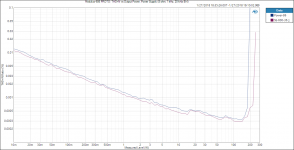
#5 - decay plots of test bass reflex box
#8 - resonance absorber results by @augerpro
#11 - link to a relating message by @rdf including link to roozen/philips-paper
#19 - new parallel 6th order bandpass test box for further investigations
#22 - dealing with enclosure resonances
#25 - chuffing audibility test
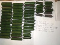
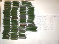
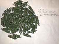
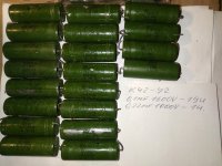
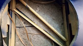
#42 - particle photos (using water sprayer)
#48 - port 2 variants and measurement results
#50 - port stalling test
#54+55 - influence of smoothed port flange
#56 - port 2 impedance results
#58 - port resonance absorber test
#81 - link to bryce doll paper by @Hearinspace
#103 - port 2 variants resulting in the same tuning frequency, with geometry drawing
#104 - photo of port 1 variants
#141 - port wall stiffening influence
#157 - port 1 variants response measurements
#159 - chuffing RTA measurement of straight port 1
#161 - chuffing RTA measurement of rectangular curved wall port and big 3d printed port
#165 - chuffing RTA measurement of flat port and small straight port
#166 - resonance absorber setup
#167 - measurment of resonance absorber lenght variations
#202 - resonance absorber filled with melamine foam
#206 - chuffing RTA measurement of 3d printed port with resonance absorber
#214 - influence of port diameter/dimension for enclosure resonance transmission
#228 - small 3d printed port drawing and measurments
#230 - testing noise of roughened port surface
#236 - port with resonance absorber documentation by @Kwesi
#249 - chuffing RTA measurements in singe dB steps (small 3d printed port)
#251 - separating resonance absorber from the port with latex membrane
#288 - link to salvatti devatier button paper
#302 - explanation of boundary layer thickness by @andy19191
#310 - impedance measurements for port 1 variants at different input levels
#320 - "progressive port geometry" concept
#324 - progressive geometry port measurements
#328 - progressive geometry port length correction
#329 - progressive geometry port impedance measurements at different levels
#330 - progressive geometry port response
#331 - progressive geometry port chuffing RTA measurement at 100 Hz
#341 - output level measurement / comparison
#349 - is airspeed the main chuffing factor? progressive port chuffing RTA measurement at 50 Hz
#350 - new particle photos
#352 - explanation of turbulent air motion by @andy19191
#363 - relating chuffing to particle displacement
#367 - first GIF-excepts of 120 fps particle videos
#390 - port variants with sound recordings by @Tenson
#391 - correct port particle displacement calculation formula by @David McBean
#395 - (1) first slow motion video: hard edge port
#407 - (2) second slow motion video: flared port
#434 - flange variant video
#438 - (3) third slow motion video: progressive geometry port
#448 - influence of air particle displacement for the excitement of low frequency noise
#449 - differences of a big and small (optimized) port for a small 2-way midwoofer
#460 - (4) fourth slow motion video: small straight hard-edge port
#468 - small very flat port - checking for boundary layer flow resistance
#503 - how to calculate the strouhal number using max port air velocity data, CORRECTION see #591
#504 - water tank simulation
#522 - @Dmitrij_S Karlson couple port
#526 - flared port geometry definition
#529 - 2 way speaeker test ports to be measured ...
#531 - ... response measurements ...
#546 - ... chuffing measurements (RTA) ...
#591 - correct calculation of strouhal number, related to peak-displacement instead of p-p- displacement (thanks to by david mc bean)
#595 - how to find a suitable port exit diameter using the Strouhal number (corrected version!)
#616 - first beta version of a simple excel sheet for tuning calculation of NFR=0.5 ports
#621 - relating the strouhal number to compression and distorsion
#624 - parametric fusion 360 model for a NFR=0.5 port by @augerpro
#627 - augerport with resonance absorber by @augerpro
#646 - parametric NFR=0.5 port model for freeCAD, including STEP and STL model
#652 - announcement by @David McBean: stouhal curve included in the port exit air velcity graph.
#654 - how I make my 3d printed ports
#680 - chuffing/noise audibility comparison: straight and flared port
#704 - big collection and evaluation of 3 speaker and 14 port variants - proposed MID PORT STROUHAL NUMBER (MPSN) parameter
#747 - updated excel calculation tool with correction and variable NFR ...
#748 - ... and the imperial version of the same calculator
#753 - comparison ports vs passive radiators
#811 - compressing the optimum geometry definition to two relevant parameters
#812 - The breakthrough: Finding compression behaviour patterns
#847 - Iterative port geometry optimizer tool


(will be updated)

Waveforming with a few small sub woofers

I've been playing around with a Rolls SX45 as low pass filter into Parasound ZAmp and two Dayton Audio SUB-1000L subwoofers.

This supports the sound of the main small speakers in my small system. It sounds surprisingly good and fast. Not hugely deep, but doesn't matter, mostly I want to add some reinforcement for the small speakers.

So, now it got me... I got these little, shallow boxes standing... and they're pretty cheap. I thought about getting four or six more and building two stacks of four up front, of perhaps put two stacks of two in front and two more -phase delayed, out of phase, in the back.... sort of creating what Trinnov calls waveforming.

https://www.trinnov.com/en/subwoofer-guidelines/

WAF is not important as this is my home office and I got a door...

Getting the woofers is easy, I got the crossover and the amps... so all I will need is the delay unit.

Well.... WAF might be a factor... when she walks in and sees those woofers eight feet up on the back wall... etc...

Any ideas... have you tried this?

For Sale Faulty Topping L30 II

Stopped working last year, barely used the thing at all, planned to try and fix over summer but dont have the time or energy.

There was no catastrophic failure like other units, although this is the "fixed" II version you can still find reports of them failing.

One day when I flipped the switch and it showed no sign of life, no blinking power LED that usually indicates a fault.

AC supply is still working and I had a look at PCB, no burnt components, I would guess the issue lies in the MCU and not engaging the required relays to give an output... in which case could probably be bypassed if the amp circuit is still ok (would not trust this amp without them though considering its history)

Not the first Topping product to randomly fail on me and far from the first time hearing it happen to others....


Asking €50

Other ads:

Attachments

  • WhatsApp Image 2025-06-26 at 23.23.51_c49af8db.jpg
    WhatsApp Image 2025-06-26 at 23.23.51_c49af8db.jpg
    68.4 KB · Views: 39

For Sale Toroid Transformers

I have these toroids available. Prices listed are prior to shipping. Shipping within USA and Canada to be discussed via PM. The two AN-3225 in the picture are already sold.

ManufModelVAPrimarySecondary ASecondary BWeight (lbs)QtyLinkRetailSaleTotalNotes
AntekAN-54125002x1154x12-111https://www.antekinc.com/an-5412-500va-12v-transformer/$ 66.00$ 45.00$ 45.00Used
AntekAS-34403002x1152x402x1572https://www.antekinc.com/as-3440-300va-40v-transformer/$ 52.00$ 45.00$ 90.00New
TriadVPT24-1040252x1152x12--1https://mou.sr/3Ifa9HL$ -$ -$ -Used

Attachments

  • IMG_1952.JPEG
    IMG_1952.JPEG
    572.1 KB · Views: 91

Any sound Differences between the Alpair 5.3 v1 and the new version 3 out now?

Good afternoon everyone. So I have the Alpair 5.3’s Version 1. I was wondering besides a few changes in the drivers mechanical suspension (mono) what makes this version 3 better then version 1? I was looking at getting the v3 but, Had no Idea if am wasting my money or is it that much better? I was planning on giving someone I know the older Alpair 5.3 v 1 if I got the new driver’s. Thanks Jeff

Programming and Coding for Putzeys Balanced Preamplifier with MUSES72323 Volume

Both sets of code have been used in anger:
Arduino Nano code
The Nano code runs on my old controller board which houses a piggy backed Arduino Nano, a PEC11R/ Alps EC11 rotary encoder, TSOP4836 IR receiver and a ULN2003A darlington array (used to drive separately mounted source select relays). It also feeds i2c data to a 20x40 LCD display.

ESP32 code
The ESP32 code runs on my new controller board housing an ESP32-DevKitC V4 dev board, PEC11R, TSOP4836, and ULN2003A. Apart from the ESP32 in place of the Nano, it also feeds SPI data to an on-board 2.8inch TFT display. Two issues I came across while getting the ESP code working on my new controller board were
  1. The TFTeSPI library runs the ILI9341 TFT SPI write clock rate as 40MHz. This is 4 times faster than the data sheet and on this set of hardware /ribbon cables is way too fast. The data sheet figure works absolutely fine in this instance.
  2. The initial hardware/software worked fine on the bench power supply but didn't want to power-on with the pre-amp's power supply . It was happy to work if the reset button on the ESP dev board was then pressed. This was due to the pre-amp power supply had a softer start-up time. (slower than the ESP's dev board's existing reset timing. A 10uF from the ESP32 reset pin to ground cured the problem.
In the coding, my remote control uses RC5 protocol as this is the coding used by my existing commercial sources that feed the pre-amp. It's straightforward to substitute other coding. Just google for whatever you need (Apple, NEC, whatever).
Hi geoffw1!
I need help uploading the program. I have purchased an ESP32-WROOM-32D, what program can I use to upload the ESP32 code that you have generously provided? Platformio+VSC gives errors.
Thanks! D'

EL84 SET Amp - THD measurements - Ideal Load Resistance?

Greetings Friends. I wanted to share the progress I've made with this little amplifier.

ELFAMP.jpg


This amp started out as a Pentode/UL switchable amp but it was pointed out to me that the PT was under-rated, so I re-wired it as a low-powered Triode amp. I took my operating point right off the EI EL84 Datasheet:

Screenshot (90).png


and borrowed heavily from the Marblewood amp's driver stage to come up with this circuit:

ELF AMP CIRCUIT AND PS.png


The amp starts to clip just below 2 watts with a 1k 500mVRMS input. I've cobbled together a testing rig using REW and have made measurements of the distortion profile of this amp at various output levels. There is a strong 2nd harmonic and relatively low levels of all other harmonics at all output levels.

test1.png


In the image above the amp is producing 1VRMS at output into an 8-ohm load, that's 1/8w and already producing 3.47% THD.

Screenshot (92).png


1/2w

Screenshot (93).png


3VRMS, just above 1w. 3rd is starting to rise.

Screenshot (94).png


4VRMS, 2 watts.

Screenshot (96).png


0dbFS. 2nd harmonic remains dominant.

So. 2 pretty watts. Flipping the switch into U/L gives a slight increase in power while adding more of the other harmonics into the mix. Bass starts to drop off below 100Hz, expected from a guitar amp OPT.

Screenshot (97).png


One question this has brought up: is it the 3.5k output transformer that gives this circuit such nice 2nd harmonics? The datasheet shows different ratios of 2nd and 3rd harmonics across varying Load Resistance which gives me the idea that a lower Ra is ideal for tubes wired in Triode. Or is it just the EL84 that behaves this way?

thanks for taking a look!

Tektronix type 564 tube oscilloscope repair

First of all I'm new to this forum and I hopei put this in the right channel.

I recently acquired a used tektronix type 564 oscilloscope. I'm starting my electrical engineering course after the summer break and I wanted a oscilloscope that I could use at home (and which I could easily service).

The issue is that I do not want to spend too much money because I dont have a lot replacing almost every part inside the oscilloscope, only the defective ones.

So the tube oscilloscope's voltage rails sag a lot when both plugins are in the oscilloscope (Vertical 3A74 and horizontal 3B4). But when I plug each of them in individually the oscilloscope's voltages are fine. Furthermore with both of them in the OG3 neon regulator tube does not loght up as compared to them being in in the machine seperatly.

What also is a weird thing is that the neon bulbs between G1 and the cathode of the CRT light up when there is 1 plugin inside it (and also when theres none).

So, I assumed the filter capacitors were problably at fault. After checking them they were fine but the values were wrong. The schematic points to using a 350uF + 10uF can capacitor meanwhile my capacitors were 160uF and 10uF capacitors.

Would this be the issue? Or is there problably some other underlying problem?

TLDR: Oscilloscope has wrong voltages and weird value caps, does that matter?

New member - Acoustat, tube owner

Hello,
I am a new member to the DIYAudio.
I owned an Acoustat Spectra 22 since early 90s, it is still with me, the interface has been updated by Mike Burgert, it was a great experience and greatly improved my enjoyment of this old classics.
I drive the Acoustate with Raphaelite CR5687 tube preamp and a custom 829B tube power amp, I am very happy with the result, the sound stage is well layered, and detail is clear and very precisely pinpointed.
Here are some pictures I like to share with everyone.
DSC_1745.JPG
DSC_1750.JPG
DSC_1747.JPG

For Sale Scanspeak aperiodic vents. $40 shipped USA lower 48

Used in bass boxes some years ago, then stored.
Nice easy way to try aperiodic.

4 small holes I drilled to use screws to mount. Designed for press fit which I also did carefully cutting hole with router.

$40 shipped usps flat rate envelope to usa lower 48.

Thanks, Don

Attachments

  • 20250607_105916.jpg
    20250607_105916.jpg
    309.9 KB · Views: 68
  • 20250607_105756.jpg
    20250607_105756.jpg
    441.5 KB · Views: 65
  • Like
Reactions: taloyd

For Sale Usher 9950-20 tweeters. $120 shipped to USA lower 48

SOLD!
In good working condition. Shipped in dayton boxes, then in usps flat rate box.

$120 to usa lower 48.

Thanks, Don

Attachments

  • 20250607_110841.jpg
    20250607_110841.jpg
    278.3 KB · Views: 75
  • 20250607_111118.jpg
    20250607_111118.jpg
    218.2 KB · Views: 71
  • 20250607_111353.jpg
    20250607_111353.jpg
    205.8 KB · Views: 65
  • 20250607_110633.jpg
    20250607_110633.jpg
    270.2 KB · Views: 67
  • 20250607_110613.jpg
    20250607_110613.jpg
    308 KB · Views: 74

For Sale Scanspeak 9300 tweeters. One needs voice coil. $85 shipped USA lower 48

Unfortunately one late night when tired I hooked one up without a crossover...man, I've only done that a couple times in 40 years of hobby at least. That one is marked with blue tape on the back.
No longer have original boxes so will use some for Dayton tweeters.

$85 shipped conus in USPS flat rate box.

Thanks, Don

Attachments

  • 20250607_091826.jpg
    20250607_091826.jpg
    288.9 KB · Views: 61
  • 20250607_084303.jpg
    20250607_084303.jpg
    381.5 KB · Views: 60
  • 20250607_091752.jpg
    20250607_091752.jpg
    339.8 KB · Views: 56
  • 20250607_091720.jpg
    20250607_091720.jpg
    250.3 KB · Views: 55
  • 20250607_091643.jpg
    20250607_091643.jpg
    322 KB · Views: 46
  • 20250607_091559.jpg
    20250607_091559.jpg
    289.9 KB · Views: 62

Waveguides for dome tweeters - SEOS-8. Monacor WG300.

All unused. Shipped usps flat rate to usa lower 48.

SOLD. SEOS-8. Pair. Black. $60 shipped. (= 20 each + 20 shipping).

One pair left! WG-300. Black. $60 shipped.

This is the best way I've learned to ship being on the west coast, otherwise prices climb quickly going east...unfortunately shipping has gone up a lot.

Thanks, Don

Attachments

  • 20250607_105030.jpg
    20250607_105030.jpg
    377.4 KB · Views: 74

For Sale 1 watt carbon comp resistors

PXL_20250626_192316571.jpg
Hey all... I just bought a lot of over 20,000 1 watt carbon comp resistors. Most values between 5.6 ohms and 22 meg. I'm thinking $5 for 10, $10 for 25, assorted values OK, plus postage. Open to offers on larger quantity. And half price on values over 1 meg.

All NOS, unbent leads. Some are shiny tin and others are more oxidized. Unknown manufacturers and age.

I checked a few dozen random samples and all but one were within tolerance. Surprising number were within 1%. I can select or match for an extra $0.50 per resistor if needed.
Here's a list:
ResTolQtyNotesResTolQtyNotesResTolQtyNotes
5R6102881K1016100K5153
7R552611K25283100K10236
8R2102061K510193110K584SOME 10%
10R101571K6517GREEN BODY120K5326
12R52791K810209SOME GREEN BODY130K5232MANY 5%
12R101542K210398150K10275
15R101782K2528180K10225
18R51602K710155180K5248
18R101473K35240MANY OLD STYLE200K57MANY 5%
22R10863K910135220K10225
24R554K3540270K5255
27R10252MANY 5%4K75121330K10262
30R5285K1510330K5321
33R102285K65156SOME OLD STYLE390k5111
33R51436K25118390k10255
39R102566K810262470k5193
51R51627K55256SOME GREEN BODY510K5130MANY 5%
56R10295SOME 5%8K210148560K10268
62R509K153620K560MANY 5%
68R1013610K516680K10414MANY 5%
82R10169SOME 5%11k525820K10290MANY 5%
91R523SOME GREEN BODY12K102791M01096MANY 5%
100R10113K5891M210238MANY 5%
120R515816K5931M510174MANY 5%
150R104218K51741M810310
160R51820k5532M0512SOME 5%
180R10307SOME 5%22K101512M210310
200R551927K10121MANY 5%2M458
220R511230K502M710358SOME 10%
240R5733K53243M35211
300R511333K101193M91071
330R522239K102855M61057
360R5043K576M2544MANY 5%
390R544347K51456M810148
390R1026147k102177M5534
430R59656K102658M21062
560R1024762K5339M1523
620R515668K519610M1045
680R108068K106511M539
820R1020775K56412M1062
820R548782K1029715M1066
910R58791K1016318M1021SOME 10%
22M5150

Attachments

Projects by fanatics, for fanatics
Get answers and advice for everyone wanting to learn the art of audio.
Join the Community
508,441
Members
7,919,395
Messages

Filter

Forum Statistics

Threads
407,765
Messages
7,919,395
Members
508,441
Latest member
fantas