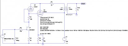
FS Mundorf AMT 23CM1.1 R tweeters

SOLD Mundorf AMT 23CM1.1 R tweeters

I am selling a pair of Mundorf AMT 23CM1.1 R tweeters . I bought it recently from its first owner because the price was very good. I have decided to sell it because I am not going to use it, I just made some fullrange speakers and I love their sound. Very good aesthetic condition, I do not have a box but it will be packaged well for shipping.
250 € pair, shipping paid by the buyer.


Another hybrid design, this time SE

I've seen this article:
r-tec2102_(07)superT-ULD-amp_KurodaT.pdf - Google Drive

taken from this site:
記事録 2021-2022

and I decided to simulate the circuit at page 109, because I already have a SE pcb that can be modded to adopt that design.

These are the results of the hybrid SE amp with EL84 at 4.3 Wrms:
Code:
Harmonic	Frequency	 Fourier 	Normalized	 Phase  	Normalized
 Number 	  [Hz]   	Component	 Component	[degree]	Phase [deg]
    1   	1.000e+03	8.272e+00	1.000e+00	   -0.52°	    0.00°
    2   	2.000e+03	1.318e-01	1.593e-02	  -90.87°	  -90.35°
    3   	3.000e+03	3.921e-02	4.739e-03	    0.15°	    0.67°
    4   	4.000e+03	1.057e-02	1.278e-03	   89.51°	   90.03°
    5   	5.000e+03	4.913e-03	5.939e-04	 -175.41°	 -174.89°
    6   	6.000e+03	2.385e-03	2.884e-04	  -95.19°	  -94.67°
    7   	7.000e+03	2.314e-03	2.797e-04	    7.19°	    7.71°
    8   	8.000e+03	3.984e-04	4.816e-05	  -95.69°	  -95.17°
    9   	9.000e+03	5.549e-04	6.707e-05	  178.40°	  178.92°
Total Harmonic Distortion: 1.668950%(1.669417%)

Attachments

  • Hybrid-LSK30AY-12AX7-EL84-SE.jpg
    Hybrid-LSK30AY-12AX7-EL84-SE.jpg
    63.3 KB · Views: 446
  • 6bq5_5w_amp.asc
    6bq5_5w_amp.asc
    3 KB · Views: 58

BiB build starting

Hello.... and the urge to build some boxes is upon me. I am a "tube head "---"audio heaven" is low power tubes and back loaded horns..----I have horns (Kirishima /F206 enabled) and a pair of horn shoppe) and a pair of Tekton double impacts gotta keep up with the competition !!!

I have (found) a pair of never used fostex 168ez drivers the BiB on the spreadsheet makes these a good beginner speaker ( learn how not to loose digits and get a positive build experience.....) (Godzilla of course)

looking at the BiB drawings for the double fold no specs but looks to be in the same box size? then I looked at the pic of Mr Cain's proto (the inverted pic) looks like maybe he just expanded the the terminus to scale for a double fold??? am I thinking right here? the longer length would expand the terminus accordingly ? found a pair of 206e's so may try them too ! would love to hear your thoughts
PS have done my own acoustic improvements best dollar return I have ever put into audio!! James

4 khz Visaton crossover wanted

I have a project where I need help calculating a 4 khz crossover.
The configuration is

1 DT 94 8 ohm and
2 W 130 S 8 ohm in parallel.

The volume is 13 liter and I use two BR 6.8 tubes

I know that a 3khz Visaton crossover looks something like this, but the W 130 S sounds very good up to 4khz.

An externally hosted image should be here but it was not working when we last tested it.


What would a 4khz Visaton crossover look like for this configuration ?

EL Jordan JX92S w/ Aurum Cantus G2si ala Jim Griffin w/ Cabinets and Crossover

DIY based on the James R Griffin design. Cabinets are braced 0.75” MDF with a maple veneer that is oxidized to a light neutral gray. Speakers are on spikes.

Two pairs of terminals. Ones on the bottom are to use the Jordan’s full range. The crossover is mounted to the back of the terminal plate for easy tweaking.

These drivers are legendary I just need to make room for other projects.

The veneer got over saturated with the oxidation mix when it was being applied and picked up a minor ripple. Seen in the photos it’s only noticeable up close.

I am happy to answer any other questions.

I am happy to pull the drivers and crossovers and just them or ship the speakers fully built. I can quote shipping, but prefer local pickup in NYC tri-state area for cabinets.

Comment when DM and make me an offer.d

Attachments

  • IMG_0323s.jpg
    IMG_0323s.jpg
    365.4 KB · Views: 201
  • IMG_0324s.jpg
    IMG_0324s.jpg
    304.5 KB · Views: 214
  • IMG_0325s.jpg
    IMG_0325s.jpg
    277 KB · Views: 195
  • IMG_0326s.jpg
    IMG_0326s.jpg
    260.5 KB · Views: 195
  • IMG_0327s.jpg
    IMG_0327s.jpg
    326.9 KB · Views: 191

47uf 450v & 200uf 450v Capacitor for CLC

Hi guys,

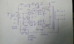
I am building a RH84 V2 EL84 valve amp and need to source a 47uf 450v motor run capacitor and a 200uf 450v electrolytic or motor run capacitor for the CLC Power Supply. I am struggling to find a suitable 200uf 450v capacitor. Should I install two 100uf in parallel or is it better to use a single 200uf?

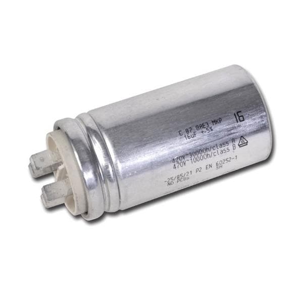
For the 47uf 450v I am thinking of using this Kemet motor run capacitor

C87_series_SPL.jpg


KEMET 46uF Polypropylene Capacitor PP 450V ac ±5% Tolerance C87 Series

RS Stock No. 911-9421 Mfr. Part No. C878BF35460SA0J

KEMET Motor Run Capacitors, C87 Series

C87 Series Polypropylene metallised film with cylindrical aluminium can type filled with resin; faston, plastic deck or cable terminals and overpressure safety device.

Features and Benefits:
High capacitance density
Self-healing metal layer
VDE, CQC and UL810 approved
Rated frequency of 50 Hz and 60 Hz
Safety device protection

C878BF35460SA0J | KEMET 46μF Polypropylene Capacitor PP 450V ac +-5% Tolerance C87 Series | RS Components
It does have 4 tab connections so I am not quite sure how raptors connect it

I have found a CD60 capacitor on Amazon that all look similar made in China with a 5% tolerance. They dont say if they are polypropylene film unlike the one further below which is more expensive.

51j3p-4olsL._AC_SL1024_.jpg


Capacitance: 200uF ±5%
Rated Voltage: AC 250-450V
Rated Frequency: 50/60Hz
Operating Temp. Range: -40℃ ~ +85℃
Size: 10.2x5cm/4.01x1.97"

FATTERYU 250-450V AC 200uF Appliance Motor Start Run Capacitor CD60: Amazon.co.uk: Kitchen & Home

Or this one here which is more expensive and 10% tolerance
Polypropylene Film CD60 Motor Rub Capacitor
51OgzpL32KL._SL1000_.jpg


Product name: CD60 motor start SH capacitor
Rated Capacitance: 200uF
Rated Voltage : 450 V AC(Compatible with AC 250V)
Tolerance: 10 %
Rated Frequency: 50/60 Hz
Size:1.7 x 3.9 inches
Wire Length: 7.8 inches
Color:White
Other: Non polar capacitor, Safe, durable and reliable,Widely used in washing machine/air conditioner/air compressor for better working motor
Package content: 1 x Capacitor

CD60 200uF MFD Polypropylene Film Motor start Capacitor AC 450V/250V VAC Volt 50/60Hz 2 Wire Safe Durable and Reliable: Amazon.co.uk: Business, Industry & Science

Out of these two which is the best to use, or should I go with a well known electrolytic from Vishay, Rubycon or Nichicon ?

Finally, is it worth adding a parallel suitable film cap around 10% of the value on these as well or is that not needed or beneficial in the psu side of things.

Thanks for your help.

Newly built amp hums n hisses

Hi everyone

I just built a small minimalistic ecc82/83 ecc99 combo, but it hums and hisses a lot! Tried a lot of things like elevating the heaters and tried to switch up the preamp heaters.
I have checked all the ground cables, but I still think there is something with the grounding that is of.. if I plug in certain pedals the hum almost goes away!
Anyone have any idea?

Cheers
Gustav

Zener diodes as protection clippers

Someone recently asked how much distortion might be introduced by using a couple of zeners as voltage limiting elements at the output of a preamp. Since this isn't something that can be guessed at from an armchair, everyone went very quiet. I was interested to know the answer, so I did a few measurements using some ordinary 10V and 16V zeners. There's nothing special about the zeners (BZX79Cxx). I just chose them because I had them to hand, and they seemed like suitable values that might be used to protect downstream solid-state equipment.

Here you can see distortion versus level at 1kHz (measurement bandwidth <10Hz-80kHz, 100k load resistance). The rise below 1Vrms is purely noise added by the series resistor. Above this distortion rises, but is lower than most valve distortion up until the clipping point. I was actually surprised at how well the clipping point is defined.
Zener_Clipping1_zps486c8f59.png


Here you can see distortion versus frequency at different signal levels below the clipping point. Offhand I suppose the rise with frequency is due to nonlinear diode capacitance. For signal levels up to 1Vrms the distortion is certainly less than valve distortion.
Above this, distortion at high frequencies could intrude, but since high frequency contect on music typically falls at 40dB/octave above 2kHz, I doubt you would ever hear anything. How often do you send out signals to SS equipment at 5Vrms?
Zener_Clipping2_zpsad21c017.png


Unsurprisingly, for the least distortion, use the highest zener voltage you can get away with, and use the smallest series resistance.

Transistor help needed

I am driving some nixie tubes off of an arduino and some bjts. I am using A5T5058
transistors driven off the Arduino output pins. It works but is kind of dim. Can someone explain to me how to size the base resistors and the resistor on the 170volt supply line? See attached.

Thank you.

Jeff

Attachments

aca v1.8 help

first amp build not going so well...
the led's work.... and that's it.

Ive looked at this for hours and don't see any glaring issues.
anyone see any obvious problems? before i send it out to a pro.

also, any recommendation for service?

ty

Attachments

  • 20210208_171958.jpg
    20210208_171958.jpg
    57.7 KB · Views: 309
  • 20210208_172010.jpg
    20210208_172010.jpg
    70.9 KB · Views: 300
  • 20210208_172025.jpg
    20210208_172025.jpg
    110 KB · Views: 299

Yuichi A-480FL + CD11nd driver

Yuichi Horn 480 finless
Beyma CD-11Nd driver.

CNC machined horn. Ready for sanding and paint or stain.
MDF. Body can still be split in half for easy sandy.

Sold

see attachment for on axis and 30deg
Thanks

Attachments

  • Photo Feb 12, 09 53 04.jpg
    Photo Feb 12, 09 53 04.jpg
    983.4 KB · Views: 285
  • Photo Feb 12, 09 53 08.jpg
    Photo Feb 12, 09 53 08.jpg
    983.2 KB · Views: 266
  • Photo Feb 12, 09 53 41.jpg
    Photo Feb 12, 09 53 41.jpg
    1 MB · Views: 262
  • Photo Feb 12, 10 04 06.jpg
    Photo Feb 12, 10 04 06.jpg
    919.2 KB · Views: 293
  • Untitled.png
    Untitled.png
    12.3 KB · Views: 261

Tantalum capacitors in audio signal path

Hi everyone.

For the last 30 years, I've been using a AVI S2000 HIGH POWER power amp. It has served me very well so far but I think it's time to give it some service and perhaps some upgrades. Besides power supply caps, and based on what I've read, I thought that the two tantalum caps located right after the input signal could be replaced as a sound upgrade. They are 10uf on the + and 100uf on the - both 6v. Given the limited space, what would you suggest ? Since there is a bias trimmer nearby, should there be any adjustments after cap replacement ? Also, any suggestions about other caps replacement. I'm an amateur but very cautious enthusiast and I'd really appreciate your advises. Photos are provided. Thank you.

Attachments

  • 20210225_102153.jpg
    20210225_102153.jpg
    879.7 KB · Views: 634
  • 20210225_103234.jpg
    20210225_103234.jpg
    812.8 KB · Views: 487
  • 20210225_103349.jpg
    20210225_103349.jpg
    607.8 KB · Views: 505
  • 20210225_103734.jpg
    20210225_103734.jpg
    815.6 KB · Views: 471
  • 20210225_102137.jpg
    20210225_102137.jpg
    901.7 KB · Views: 485
  • 20210225_095313.jpg
    20210225_095313.jpg
    997.8 KB · Views: 338

Salas shunt reg for TDA1541A question

I've searched the forum, but I found no info on this (granted I didn't spend hours searching).

I have this (PCB designed by dvb-project) fully populated, except for the current limiting resistors. I left those unpopulated as I don't know what values to use. The LED's are matched and the 2SK170BL's are all matched within 0.01mA(not that it's needed, but I had 16pcs matched within +/-0.01mA).

So, if anyone knows what values to use for the 5W current setting resistors, I'd be grateful if they'd share that information.

Attachments

  • Salas_shunt_TDA1541A.jpg
    Salas_shunt_TDA1541A.jpg
    397.9 KB · Views: 195

Hammond 370BX - winding resistance for rectifier calcs

Does anyone know the primary and secondary winding resistance for a Hammond 370BX (with a 230V primary)? I am trying to work out what would be needed to meet the minimum resistance for a valve rectifier (EZ80, and yes I know it has a 5V winding but I will be using additional filament transformers). I can't spot anything obvious in the datasheets.

Salvaged CD-6 DAC board

Hi all,
I salvaged from a Cambridge CD-6 (brocken transport) a dual TDA1305 balanced DAC board.
Since I cannot find any hi-res image of the schematic, could you help me to find where to connect the input signal? Dac pcb has on-board psu and is very similar to the Dacmagic one.
Here's the only service manual I found:
Cambridge Audio CD6 Compact Disc Player Manual | HiFi Engine

The idea is to connect a Broskie's unbalancer before the opamps...

Cheers,
Vincenzo

Cross-over design software with actual measurements

Hi all, newly signed up but have been reading posts here for years. Many years ago a buddy of mine and I did some work on replacing the crossovers on some speakers of mine and it made such a huge difference. I want to do that again for the recent speakers and wondering what software people would recommend. I see lots of options for cross-over design. But I want to be able to measure the performance of the drivers in the cabinet and use that response curve to simulate the actual final performance of the system/cross-over. We did that before with raising up the speaker up into the air and measuring the frequency response. Our "poor-mans" anechoic chamber.

So there are really two elements I'm looking for, maybe one package can do it all but happy to get separate software if it will work together.

1. Software to measure the response curve of the drivers, I have the mic and audio interface already.
2. Software to design the cross-over that uses the frequency response curve from step one, not a simulation of the driver based on parameters. (Maybe that is standard now?)

Hopefully I didn't miss something but I see lots of software options but really not sure how to compare them to each other.

Thanks

Dynaco PAS 3X - help with an old modification

Hi

I have an old Dynaco PAS-3X I brought some years ago. I think it is time to fix this and get it running again.

When I look at it I do see some old modifications. I have no luck in finding any info about this old mods. Hope someone of you can tell me something about it.

The first mod is on the power supply. The old owner put in an extra electrolytic cap, and also an extra coil. Now the schematic looks like this:
An externally hosted image should be here but it was not working when we last tested it.


Is it OK to have it in this way? Is it good, or should I do anything else? Maybe back to original?


Next old mod is on the PC5 - Line board. Here is a bunch of resistors and caps changed to new valeus. My plan is to change all of the components to better ones, but so far I didn´t notice any mods to the line board, just on the RIAA-board. Does anyone recognize this mod? Should I keep these values or change them back to original?
I DO want to keep the tone controls. Especially while it is a PAS-3X, so I have the possibility to center the tone controls and take them away from the signal path.
Here is a pic whats on the line board in my amp:
An externally hosted image should be here but it was not working when we last tested it.


I also add a picture with the original values:
An externally hosted image should be here but it was not working when we last tested it.


Anything else you may see that is wrong or also is an old mod?


My plan for this PAS is:

- Do the curcioaudio.com mod for the RIAA
- Change volyme-pot to an ALPS
- New electrolytic caps instead of the old ones
- Rewiring the input and maybe change the selector switch (it is in good condition)
- Take away Tapeswitch, Filterswitch and Loudnessswitch from the signal path.


Best regards.
Rampitsch

DIY Tonearm: Double Vertical Spikes - Help Needed

Hey All,


I'm working on a tonearm design which uses a combination of ball bearings for horizontal movement and spikes for vertical. I will share my ideas for feedback soon.

Right now, I need some assistance in sourcing 'spikes' for the vertical bearing. I would like to use something similar to what is used on a Kuzma 4Point tonearm (see below photos). Any ideas?

Having read through existing threads, there are some ideas that might work (football boot spikes for example). However I thought I'd open this one up for any further specific suggestions.

The main criteria from my perspective (in relation to my planned design), is that the spikes need to be small (with a small tip radius) and hard.


Cheers,


Fish


Kuzma Bearing Spikes SMALL.jpg

Base stopper resistors are necessary for output stage emitter followers

Base stopper resistors are necessary for output stage emitter followers, especially in output stages with several complementary emitter followers in parallel. Ideally, an emitter follower should not be driven from a low source impedance without either a ferrite bead or resistor in its base -- or both.

Read the following:

https://www.analog.com/media/en/technical-documentation/application-notes/an47fa.pdf

Attachments

How to filter out radio noise

I've just finished a NE5534 buffer feeding into a couple of NE5532s and everything works as advertised except..when I touch the chassis, I get a sports radio channel through the speakers! The station is well tuned, sounds like AM and comes on and off by touch.

I implemented an input filter before the DC blocking cap with fc=72KHz (1k/2n2 - I ran out of 1nF).

The circuit is fed from single supply 12v. There is 100uF on the rail as well as 100nF directly at pins 4 & 7 of the NE5534 (pins 4 & 8 of each NE5532).

The PCB has a single sided ground plane which is covered by solder mask (but might have incidental contact with the chassis). The input / output / power are attached to a plastic faceplate. The housing is a small Hammond enclosure:

attachment.php


This is the first part of the schematic:

attachment.php


Any suggestions on how to get rid of this radio station?

Attachments

  • 9287825-40.jpg
    9287825-40.jpg
    5.1 KB · Views: 382
  • Front end.png
    Front end.png
    64.9 KB · Views: 414

Magnavox Amp 169 AA schematic

Hi!
Can anyone help with Magnavox Amp 169 AA or Magnavox Amp 169 BB schematic.
Tubes used: 6AN8 (pre and split) - 6V6GT X2 (push-pull output) - 5Y3GT (rectifier)
I've got a Magnavox AMP 169 AA that I am planning to rebuild.
Could only find in poor resolution, many values are unreadable (
Thank in advance !)

Attachments

  • Magnavox Amp 169 AA_Scm_Small.jpg
    Magnavox Amp 169 AA_Scm_Small.jpg
    40.5 KB · Views: 784

DAC as a preamp???

I need a new DAC. I use my computer for volume control, but do not trust it. I want separate volume control. The 90s me would have immediately thought preamp. But since I need a new DAC, my question stands ... DAC as a preamp?
I've posted more info about my system below.
I need some advice on the best way to go about getting volume control for these powerful asp1000 amplifiers. I've read about the high input impedance. I use a computer for my source playing Flac, wav or hi-res audio files. I'm using a very simple dongle Style USB DAC that sounds okay. I have choices, but do not know what my best bet is. For simplicity, it would seem I should just buy a better desktop DAC, such as and SMSL M500 and use the volume control knob on front. Or ANY other DAC with a volume control for that matter. I know I can use my volume control the USB. Provides through the keyboard on my computer. But with amplifiers this powerful, I figure I should have a volume control to prevent issues such as full volume noise blasts, which have happened before when the computer glitches. My second option would be to purchase a regular preamp. This would be the most expensive option, as I would want something at least as good as the Schitt Freya +, and that is $900! I would still need a decent DAC upgrade. This gets expensive with my health issues at hand. The last way I could go, is something like an all tube gain stage. I would still need a DAC, but a simple gain stage kit should only be a few hundred at most. The other two options I can think of, would be the pass B1 buffer clone kit preamp for 150 dollars, but I don't know if it would play nice with a high input impedance of the icepower amp. The most simple and cheapest route, would be be using the Sure digital volume control option. But I do not know how high fidelity that would be. I could really use some help. I've been out of this hobby for about 10 years now. I feel a bit lost and appreciate everyone who has helped so far.
  • Like
Reactions: DblAA

Small Syns 3d replacement waveguide

Small Syns 3d printed replacement waveguide

I thought I would put this here as to not clutter up the main Small Syns thread until they are done.

I am attempting to design a drop in replacement for the horn in the SmallSyns, as it is all but impossible to purchase it now. I'm hoping to just get it close, so no (or a very minor value change) is needed to drop into Bill's design.

The original horn was the SEOS15 sold by DIYSoundGroup, and designed over at AVS Forums by committee. The end product design work was done by jzagaja. Final specs were listed here, but there is a lot of wiggle room there. Later talks put the throat at 16deg with a small conical section before the transition to the OS profile. It reads like this was for the fiberglass horn, so I assume the plastic molded horn used the same profile.

I have never seen an SEOS15, so this should be fun.

I have went through multiple dozens of designs, done in several different ways, and narrowed it down these two to try out. They were designed in two different series, and both are close. These are the targeting shots.

From left to right they are models 15b and 15bb3.

Polars shown with the same layout with Horizontal up top and Vertical on the bottom. No cd throat length added here.
The pink trace is 45deg. 5deg spread from 0deg on up.


Test measurements and explanations starting in post #15

Attachments

  • Capture.PNG
    Capture.PNG
    132.3 KB · Views: 261
  • polar.PNG
    polar.PNG
    231.1 KB · Views: 261
  • SPL.PNG
    SPL.PNG
    332.5 KB · Views: 247

Tone burst as a non-stressful test of maxed output

A software generated tone burst can take the stress out of some types of amplifier testing. An example is when checking loadline performance and operation in to pentode saturation region where continuous tone testing may stress valves and other circuitry.

I was just using REW software's tone burst function to generate 2 full sinewave cycles, along with a digital scope to capture output stage anode voltage and cathode current in a fixed-bias, class AB, pentode push-pull amp of nominal 100W rating. The ears also get it easy if a test speaker is being used instead of a power resistor.

A few different test conditions came to mind during testing.

The amp I had on the bench was a quad 6L6GC, and the 1.7kohm PP output transformer wasn't nicely aligned for such a quad (which would have preferred 2.5k PP from the datasheets for 400V screen and 450V B+). Testing with the output stage overdriven clearly showed max cathode current and min anode voltage to be hitting the pentode curve either over or under the knee when rated or 2x rated secondary loading was applied.

Plots below show orange trace as anode voltage (approx 200V/div), and blue trace is cathode current (100mA/div) for one 6L6GC. Idle condition on LHS of each plot is nearly 500Vdc and 25mA. 0V and 0mA is one division up from bottom. Left plot is for rated 1.7kohm PP of output transformer, and right plot is for 3.4kohm PP (16 and 32 ohm resistive loads on a 16 ohm speaker tap). 2 cycles of 1.5kHz with gross overload of output stage.

V5%2017%20ohm.BMP
V5%2034ohm.BMP


The saturation region performance of each valve in a quad can also be compared by noting the individual max cathode currents. The quad I had was vintage and certainly showed some variation in individual max current levels.

If your scope can present captured waveforms in XY mode, then theoretical loadlines become reality measurements. Plots below are for 1.7kohm PP loading (16 ohm speaker), and the speaker load alters the voltage and current waveforms a bit when the left plot is compared to resistive load plot above. In the XY plot presentation of the same data, the Y-axis is 100mA/div cathode current (blue trace in LHS plot), and X-axis is 200V/div plate voltage (orange trace in LHS plot) but origin (0V) is two divisions from left side.

V5%2016ohm%20speaker%20high%20level.BMP
V5%2016ohm%20speaker%20XY%20high%20level.BMP


Perhaps more for guitar amp applications, capturing grossly overloaded waveforms can be insightful, and a little less stressful than compared to turning up a volume pot and watching a scope waveform for a few seconds and then turning the volume down.

Now I need to think up some test situations where I can get one or both primary half-windings to exceed the normal voltage window limits from 0V to 2x B+, as I'd really like to test the use of MOVs for over-voltage protection across each half-winding of an output transformer.

Ciao, Tim

HH Scott 299C

Decided the best way to have my own 299C was to fab one from the ground up. The PC boards were designed by North Reading Engineering and sourced from US suppliers. Chassis plate is 1/4" Aluminum alloy, CNC machined with brushed finishes.

Haven't decided if selling the amp either as assembled, a kit or partial build but here's the webpage I made for it.

North Reading Engineering

I've got a pair of Lundahl OTs on order for the amp as well and may offer a version using them also.

Some photos:

build2_34.jpg

build2_16.jpg

build2_38.jpg

$ Channel ICEPower 500ASP/A in an Audio Research Style Chassis

4 Channel ICEPower 500ASP/A in an Audio Research Style Chassis

Hey all, I have my four channel ICEpower amps - two 500ASP powering two 500A, in a nice Audio Research style chassis for sale. Input is XLR Balnced only, but you could just use a XLR to Single Ended adapter for RCA SE connections to preamps.

Mains switch on back, front left switch puts 500ASP in standby, while right front switch puts the 500A into standby. A nice Blue LED power indicator in middle...

Just trying to downsize the many amps I have...this one powered a set of Martin Logan CLS and two subs - worked awesome. I already have a pair of 1000ASP and other class D amps, so just need to sell off some stuff.

Beautiful 3U ARC Style chassis no longer on ebay (cost a small fortune), and this is my last one...and the ICEpower modules are now selling at Partsexpress for a price check...

Weighs a ton, so local pickup in West sub of Chicago would be best, but can ship if buyer pays...

How about $650 + ship?

Attachments

  • 2.jpg
    2.jpg
    778.3 KB · Views: 797
  • 3.jpg
    3.jpg
    994.1 KB · Views: 769
  • 1.jpg
    1.jpg
    687.7 KB · Views: 749

Preamp w/output trans.: on/off transients?

Tube line preamp only: 5V4 rectifier tube; audio circuit employs only one 5842 RF tube > Magnequest DS 050/600 output transformer, currently wired for 18 dB gain.

Generally tube preamps must be fully stable, then power up the amplifier (SS in this case), and conversely the amplifier should be fully discharged before turning off the preamp.

Does the rule still apply with an output transformer-coupled preamp? I have turned the amp on within a few seconds after the preamp; so far no noise.

Amp is a Pass designed dual mono mid-80s Adcom GFA-535 60W original, recently fully restored, stripped/refinished chassed and with several upgrades including a new after market PS board.

Tenacious 6+. 6cm Full Range 3D Printed Driver

Hello everyone

Been a little while but back with my first 3D printed design based around a new magnet motor and new magnet size. In this case, 20mm N35 countersunk magnets.

The long term motor to match the Bl values I need will come from a larger build, but these seem like a easily accessible and flexible choice. Here is the T&S values, along with 2 frequency response graphs. There are 2 depending on the material chosen for the 3D printed cone:

The design is a Patreon exclusive, but wanted to show you all the steps forward that have been taken. There are still things to improve as we scale up a bit more, but these are a big step forward and helps to show the capabilities of 3D printing as a whole.

Any questions at all, feel free to ask away. One step closer to a end product!

Paul 🙂

https://twitter.com/Polymate3D/status/1365803867372466176
https://twitter.com/Polymate3D/status/1365667601968414732

^ Twitter posts are quick videos of them in action

Attachments

  • Tenacious 62.jpg
    Tenacious 62.jpg
    38.3 KB · Views: 152
  • Tenacious 6+ Datasheet.jpg
    Tenacious 6+ Datasheet.jpg
    267.4 KB · Views: 147
  • Tenacious 6+ Impedance.jpg
    Tenacious 6+ Impedance.jpg
    282.5 KB · Views: 157
  • PXL_20210227_134351726.jpg
    PXL_20210227_134351726.jpg
    620.3 KB · Views: 160

Stereo preamp advice needed

We were burgled and one of the units stolen was our Cambridge Audio Azur 840

I am still very much in the analogue realm and while there was a NOS CAA 851 going cheap those are digital only and I didn't want to go with a full set of patch boxes for A2D.
So at the moment we are using one of my old Rotel H/T preamps and some old gear and due to the sudden demise of the NAD in the shed I have no music in there either.
I have a feeling that the insurance company is no going to come to the part with an honest "New for old" replacement.
Looking for some advice on possible replacements.
New, NOS perhaps and second hand very possible especially if I could get a rebuilt Yamaha C-80
No budget as yet but I have an advisory letter from the local Hi-Fi dealer [ where we bought the unit] that the closest comparable and available unit is the new Yamaha C-5000 but the dealer thought our old unit was superior. I actually thought the old Yamaha C-80 was better but my ears are old.
Advice and please no commiserations as we feel pretty rotten as it is, but at least they left my Trio monoblocks and the Rotel 1070

Problem with led bias on phono preamp...

Hi, I state that I am a beginner. 😀
I have an ear834.

Polarized V1 stage with Rk 1,8k / Vk 0,9v / 0,50mA.
Polarized v2 stage with Rk 2.0k / Vk 1.1v / 0.55mA.

On V2 I tried various IR leds and diodes, the best options for the same Vk are IR leds or 2 x 1n4148. All good..the preamp sounds happily.

I then tried to put a CV (led or diodes) on the V1 stage ..... but nothing.
Does not work.
I assumed that perhaps little current was circulating, so I gave more current to the IR LED (and diodes) taking it from the B + (285v), through a 220k R, about 1.3mA. Still not working 🙁

Maybe the valve is swinging?
Here's what I see.
Yellow is the incoming signal.


For now I have tried 2 x1n4148 and IR LEDs. Same result..a kind of square wave.
But on V2 everything works smoothly.
I specify that my ear is modified. the active riaa also includes the tube V1 (as audioresearch sp6).

Thanks for any help!

2 way seas + morel

New 2-way project with seas p21 rex and morel mdt 12.

Under construction.

Attachments

  • IMG_20201121_165502.jpg
    IMG_20201121_165502.jpg
    893.2 KB · Views: 545
  • IMG_20201121_182535.jpg
    IMG_20201121_182535.jpg
    876.2 KB · Views: 534
  • IMG_20201121_205846.jpg
    IMG_20201121_205846.jpg
    888 KB · Views: 520
  • IMG_20201122_190845.jpg
    IMG_20201122_190845.jpg
    877.3 KB · Views: 505
  • IMG_20201122_190856.jpg
    IMG_20201122_190856.jpg
    766.7 KB · Views: 494
  • IMG_20201122_191203.jpg
    IMG_20201122_191203.jpg
    949.4 KB · Views: 164
  • IMG_20201122_191237.jpg
    IMG_20201122_191237.jpg
    955.7 KB · Views: 138
  • IMG_20201122_191121.jpg
    IMG_20201122_191121.jpg
    887 KB · Views: 148

Condenser microphone and mute switch

Hey.
I've got problem. I've recently made phantom powered condenser microphone for violin, nothing special, but I must repair the problem as soon as posible, because someone desperately need the microphone.

I've build microphone preamplifier using that site:
Powering microphones
under Balanced electret microphone circuit.
It works well for my needs. Or at least, it worked well until I didn't add MUTE switch. So the problem is I can't get rid of the bang while switching from mute to unmute and vice versa. The switch is DPDT.
If you could give me some advice how to connect the switch(or add some resistors, capacitators, whatever), so there won't be that BANG while switching.
I had tried some connections, but they weren't good.

thank you for help, and I hope you could understand my engilsh🙂

and the circuit is(without switch):

Attachments

  • vezje.jpg
    vezje.jpg
    36.1 KB · Views: 495

Speaker Upgrade Options

Hello all!

Recently aquired a 1965 Clairtone console stereo, recapped the amp and serviced the turntable. Plays very well for its age. The speakers could use an upgrade and I'm looking for ideas. First would be to remove the speakers and install newer components, however I do not want to modify anything inside the cavity, so making new speakers fit might be a challenge. I thought of building cabinets that would slide inside the existing cavity, however there are cardboard ports at the top.

This unit has external speaker outputs, so when I wanted to listen I could haul out the speakers and hook them up.

Current speaker configuration is one 10" woofer and two 3-1/2" tweeters for each channel.

Room type is living room / kitchen (open concept) with high vaulted ceilings, with listening position 45deg diagonal off the front of the unit. Not optimal, but I'm not looking for perfection, just a really nice upgrade.

Music preference is classic rock, jazz, blues, some classical.

Thank you for looking!

Attachments

  • 1614463062589_IMG_5777.jpg
    1614463062589_IMG_5777.jpg
    402.6 KB · Views: 170
  • 1614463069096_IMG_5924.jpg
    1614463069096_IMG_5924.jpg
    407.9 KB · Views: 175
  • 1614463074186_IMG_5921.JPG
    1614463074186_IMG_5921.JPG
    845.4 KB · Views: 210

Any benefit to replicating a Freya-type device with Pass DIY?

The Schiit Freya+ provides the ability for a user to switch between passive attentuation, buffered stage, and tube stage with gain with the push of a button/switch. Seems like a similar setup could be put together switching between a passive attentuator only, a buffer board, and a Korg board.

One friend suggested he prefers them in separate boxes because it give him a chance to play with combos of equipment more readily. I think the simplicity of them being in one box leaves me rack space.

Waste of time? Cool idea? Technical nightmare?

~Chris

Major Frequency Ranges

In this post Earl Geddes identified three major frequency ranges and explained his reasoning:

I view sound system design in three major frequency ranges - low frequencies, where modal effects and the room dominates, there is no imaging or psychoacoustics to worry about, its simply a matter of adequite output and smooth spatial and frequency response (more on this in another thread); 200 Hz - 1000 Hz, probably the most forgiving of the three regions, our auditory system is only just begining to be capable of resolving spatial aspects (localization) and it is not yet very good at resolution of time delays, reflections and frequency response. If you are going to compromise something do it here as it will have the least noticable effect. Above 1 kHz is where we live as far as music is concerned. This region is ultra sensitive to time delays, reflections, frequency response, diffraction, all the things that tend to mess up coloration and imaging. Mess up this frequency region and you won't be able to recover the sound quality. Here is not where you want to make compromises for sound quality.


1) Do you agree with Geddes and follow his advice in your designs?
2) Are there additional ranges in the high frequencies that make them less critical to listening?

I place an upper limit on high frequencies at 16,000Hz because I can't hear frequencies above that. But are there additional ranges where performance is less critical? For example, get 1,000Hz to 5,000Hz right but don't worry much about 5,000Hz to 16,000Hz because the wavelengths are so short you can no longer localize them or identify colorations from room reflections. (To be clear, I made that last sentence up as an example not as a fact. I have no idea where high frequencies become less critical other than the physical limit of my hearing.)

Building an all tube gain stage ...

I realized I should have put this thread here in the tube section.
I simply cannot afford this product I want. I'm wondering if there is anyone I could pay to help me design a clone of this? Or if there is a DIY product on the Forum like this with plans I could build one from? If you scroll down the page you can see a photo with the top off.
DECWARE all tube gain stage / purist preamp model ZSTAGE

Spice Model TDA2040

Hi

I am about to build some test equipment and was considering using a TDA2040 in the output. My concern was the stability at unity gain. Has anybody a spice model for a TDA2040 or TDA2030? Has anyone tried running these at unity gain?

The idea is to generate a spit supply from a 24 volt plug pack (wall wart to some) so the supply will be +/- 12 volts.

The 12 bit DAC output from a Xmega micro will supply the signal. DC to audio frequencies only. Voltage out +/- 8 maximum. Good output control at mV required so I may have digital gain control (relay Hi Lo).

Regards Ken

Let's discuss a professional circuit

I want to present a re-engineered circuit of a professional headphone amp. There was no documentation therefore i had to get the circuit from the double sided printed board with smd on the upper side. Unfortunately, the bottom of the board was not accessible, but I could measure the missing connections. The circuit is attached as a PDF (project_kh.pdf). Let me say it's not my invention so I don't own the copyright. I double checked the circuit as it is very strange in some parts.

I checked the quality of the amplifier using RMAA, have attached the very good measurement results as a PDF. It's the Project Head Box 2 DT990 Pro file, the other file (Corda Jazz) was uploaded by accident and I can't delete it... 🙁

What I don't understand at all is the output stage, which is a pure class B with nearly no quiescent current, but it has a driver stage class A in front of it where 18 mA current are wasted. What is the advantage of this design?

What makes me very curious is the feedback from the VAS stage to the input stage via resistor R10 to transistor T2. I've never seen such a combination. Any ideas?

Heinrich

Attachments

FS: Pioneer SX-7 Receiver & CT-6R Tape Deck Operating Instructions & Amp Schematic

FS: Pioneer SX-7 Receiver & CT-6R Tape Deck Operating Instructions & Amp Schematic

I have the Operating Instructions for the Pioneer SX-7 Computer Controlled Stereo Receiver and the CT-6R Stereo Cassette Tape Deck. A schematic for the receiver is also included (no schematic for the tape deck).

I tried selling these on eBay and did not find a buyer. Any interest here? Price is just the $7.95 shipping in a USPS Flat Rate Envelope (USA Shipping). I'd hate to just toss these in the recycle bin (especially the schematic).

7upbPcj.jpg


T0CRpcK.jpg


YU4RGE0.jpg

Hand sanitizer

One for the chemists or maybe just the smart guys out there.
I have bottles of Methyl Hydrate and bottles of Ethyl alcohol 50%. Can I just mix those two together to achieve the 70% solution they suggest is ideal for hand sanitizing or is there more I need to know. Is it better just to water down the MH to 70%? I have more than I need of both so I'm not using anything precious here.
TIA.

How flat should I expect a heatsink to be?

Hi,

I've just received a heatsink for an amp I'm building (main thread over in Instruments and Amps, I split this here because it's a more specific problem) and the surface isn't flat. There is a slight concave along the width which means the aluminium angle won't mate properly. I've attached pictures of the problem.

The question is, how usual is this for heatsinks? Can I expect to return it and get a flat one or are the odds that that will also be curved? Should I just take it to a machine shop and have them skim it flat?

Thanks,
James

Attachments

  • heatsink 1.jpg
    heatsink 1.jpg
    493.6 KB · Views: 231
  • heatsink 2.jpg
    heatsink 2.jpg
    540 KB · Views: 231

Rebuilding Beveridge Circuit Board Stators

Has anyone here rebuilt Beveridge circuit board electrodes/stators? I'd like to know what I would be getting into before I start.

I've always been fascinated with Beveridge ESLs -- in pristine shape, to me they sound compelling. Technically they are a clever series of trade-offs. I think they can be made to sound better with a different set of trade-offs. I'd like to try.

So I bought a pair of Model 5s -- their lowest end model -- that were available locally for a very reasonable price. I'm still assessing what I have and what needs to be fixed. To those not familiar with the Beveridge line, the Model Five is a five foot tall, 18" diameter cylinder that contains a 3'x1' electrostatic element and a 10" woofer. The ESL front wave passes through an acoustic lens (waveguide); the rear wave is damped. The woofer is downward facing, and occupies the lower 2' of the enclosure. The crossover is at about 150 Hz.

This pair dates from 1984, and has had some attention paid to it over the years. There is non-crumbing grille foam, and the woofers work, so they either have been replaced or had the surrounds repaired.

The electrode/stators show quite some loss of aluminum from the diaphragm, mostly down the center line. Interestingly, the capacitance values are not that far off from what was written on the panel edges. They do work, but are very old, and probably should be refurbished before I do much else.

I've scoured the web, and find little information on the Beveridge circuit board electrodes other than that they are notoriously unreliable. I assume they generally follow Beveridge's patent, so use copper on the inside of a PCB (it is backed off from the openings) and insulated with about 250 um of Nylon. The diaphragm claimed in the patent is Mylar (or other PET equivalent) that is coated on both sides with Aluminum. No diaphragm thickness is mentioned, but I assume that it is the standard ca. 4 um thickness. The patent further claims the edges are sealed with a nonconducting silicone elastomer, but if that is used in mine, it long ago has lost its compliance.

Of course the diaphragm should to replaced. I've yet to identify a source that sells double-sided Al-coated PET of a suitable thickness. I assume further that I'll have to examine the integrity of the Nylon that insulates the copper and fix as is necessary. Other than that it should be pretty standard as far as ESL construction goes.

I think. I'm assuming a LOT, and before I dive in I'd like to see if anyone else has done a similar refurb. Is there anything I'm missing/overlooking? Does anyone with experience wish to talk about it?

Discrete crossover, sanity check

Hi,
as my minidsp seems to increase the noise considerably and I usually try to keep it simple,
I plan to make a PCB for a relatively basic 2-way crossover.
As nice as it is playing with configurations I doubt the minidsp doesn´t influence the signal in some way.

Idea is to have the same buffer-schematic for most stages, except input-buffer and line-out/headphone-out (which are without most of the passive elements)
It is laid out so one can make a 12dB-HP/LP, high shelf-, low-shelf-filter per block (or combine within the block).
The schematic for the buffer show resistors to the left of the buffer which really should be read as "Z" and thus R,C or L.
Footprint is 1210 and so it can take R&C of various footprints (1206 and even some 0805). Everything will be handsoldered.

The used diamond buffer is really the simplest version of them all but seems to simulate well enough, even down to typical headphone-loads.
DC-offset seems low enough that only at the in- and output of the whole circuit a capacitor would be needed.

Power will be supplied with a Jung/Didden-super-regulator from the DIYaudio-store.

If you see any errors or have any comments you´re welcome!

Thanks & best regards
Jens
PS.: I used the "replicate layout"-plugin from Kicad and it works really well (if you refine hierarchical sheet´s layout and don´t have any errors🙄)

Attachments

  • xo-schem.jpg
    xo-schem.jpg
    134.7 KB · Views: 388
  • hp-lp-shelf-buffer.jpg
    hp-lp-shelf-buffer.jpg
    47.7 KB · Views: 395
  • xo-3d.jpg
    xo-3d.jpg
    252.6 KB · Views: 368
  • amplifier_diamond-buffer_to92.asc
    amplifier_diamond-buffer_to92.asc
    2.2 KB · Views: 113
  • db-schem_ltspice.jpg
    db-schem_ltspice.jpg
    158.6 KB · Views: 375
  • Like
Reactions: limacon

Transistors metal holders unclip help

Hi, I have this amp - US Acoustics SD-640 and it needs some repairing. Please somebody to tell me what is the right way to unclip these metal holders that keep transistors to the heatsink. It's probably a common procedure but it's first time for me of this type without screws, just clipped. I couldn't find any info about this in the net. Thank you very much

Attachments

  • dscf0015_14.jpg
    dscf0015_14.jpg
    213.3 KB · Views: 83

Hi-eff speaker inspired by Von Schweikert Unifield 3

Hey guys. I'm thinking about designing and build a high-efficiency speaker I got inspired by Von Schweikert Unifield 3 and I wanted to write a little about it hear to hear your opinions about this and to use the wisdom of the crowds.

this is Von Schweikert Unifield 3. a three-way speaker consisted of an 8" Seas W22EX001 woofer, 5" fullrange Fostex FX120 and a ribbon tweeter/supertweeter Fountek NeoCD3.0. But there is something interesting about this speaker the five-inch Fostex covers from 80hz up to ~8khz. I would say this makes this speaker a full-range loudspeaker with additional aid from a woofer and a supertweeter. there is no cross point at the critical range of midbass and midrange and upper midrange.I couldn't find more details about its crossover but I suppose the designer has used Fostex FX120 natural roll-off to avoid using LPF. the lower part also might be limited by the volume of the 5-incher sealed enclosure. Maybe not. I'm not sure. after all it's ~88dB sensitive.
take a look at it:
photo_۲۰۲۱-۰۲-۱۲_۱۹-۵۹-&.jpg

My idea is to design a pretty similar speaker but with higher efficiency. at least 96-97db. I yet have to decide if I'll make this activity with some Hypex Ncore amp or just do it passively. I have several choices for the woofer. Faital 15FH520 or 15PR400 or Beyma 15LX60V2. For supertweeter I'm gonna use Aurum Cantus G1 or Beyma TPL-150H or Aurum Cantus AST25120. the main driver would be the fullrange. a five-inch fullrange at 8khz will have
a dispersion angle about 25 degrees. not soo good? the eight-inch will beam even worse. an eight-inch will have almost same dispersion at 5khz.
My idea is to use Tangband W8-1772. I think at 20-25degrees tilted it will be enough good to cover up to 5khz but after all I think I may have to use a LPF on it.

any idea is welcome.
Projects by fanatics, for fanatics
Get answers and advice for everyone wanting to learn the art of audio.
Join the Community
507,774
Members
7,888,093
Messages

Filter

Forum Statistics

Threads
406,220
Messages
7,888,093
Members
507,774
Latest member
pete2000