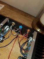
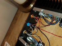
first amp build not going so well...
the led's work.... and that's it.
Ive looked at this for hours and don't see any glaring issues.
anyone see any obvious problems? before i send it out to a pro.
also, any recommendation for service?
ty
the led's work.... and that's it.
Ive looked at this for hours and don't see any glaring issues.
anyone see any obvious problems? before i send it out to a pro.
also, any recommendation for service?
ty
Attachments

checked PSU voltage at amp pcbs?
LED will work even with few volts
saying that for case of damaged PSU jack, switch, malfunctioning PSU ......
LED will work even with few volts
saying that for case of damaged PSU jack, switch, malfunctioning PSU ......
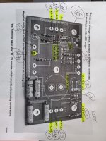
PSU 23.8v
Front switch input (lower tab) 23.8v
Front switch output (upper tab) 23.7v
PCB V+ 23.7v (both boards)
Q1 D .2v
Q1 D 5.7v
Q4 D 23.6v
Q4 D 23.6v
Front switch input (lower tab) 23.8v
Front switch output (upper tab) 23.7v
PCB V+ 23.7v (both boards)
Q1 D .2v
Q1 D 5.7v
Q4 D 23.6v
Q4 D 23.6v
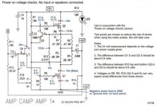
Print out the build guide page with the voltages shown. I'm not 100% sure if this is the latest, but it's to give you an idea of what to look for. It shows voltages at key points around the circuit.
Measure these voltages, write them down on your printout, and post pictures of your results for us to look at. You may find "good, good, good, oops" and then see the problem when you see the "oops"
Also, I can't tell for sure, but are your solder joints showing a good connection on both top and bottom of the PCB? One bad solder joint could be a potential problem. I've gotten into the habit of soldering one side of the board (usually the bottom), then flipping it and touching up any joints on the top side that isn't getting good coverage of the device and the pad. Example. Stuff resistors, solder all on the bottom, flip and touch up on top. Then move on to next device type, rinse, repeat.
Attachments

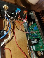
Let us know what you find. Did you measure each resistor before putting it in? Have you confirmed the right values are where they are supposed to be? Solder joints looking good? Are the little transistors right? right position, right orientation?
well i found a problem
i have a transistor ztx450 in Q3 AND Q4 on one board
and jfet lsk170 in Q3 AND Q4 in other board
i have a transistor ztx450 in Q3 AND Q4 on one board
and jfet lsk170 in Q3 AND Q4 in other board


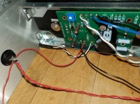
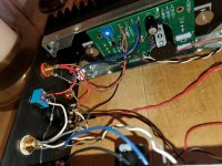
Do you have a solder removing tool you can use the other boards? Swap the transistors in the wrong spots and see if the boards work as expected... If you didn't smell the magic smoke being released you may be good to go after the swap.
OK have boards all fixed up.
Is it ok to test these (power them up) without sinking the MOSFETs?
I want to comfirm they are "ok" before i buy another case for a second amp.
Is it ok to test these (power them up) without sinking the MOSFETs?
I want to comfirm they are "ok" before i buy another case for a second amp.
- Home
- Amplifiers
- Pass Labs
- aca v1.8 help