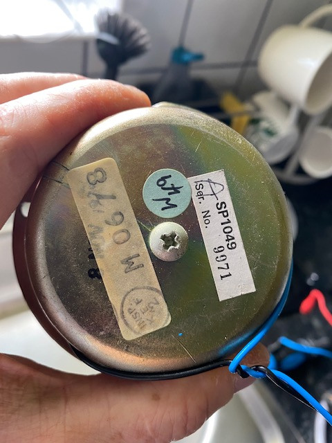
PINK TRIANGLE PT TOO PSU PROBLEMS

Dear DiyAudio:
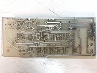
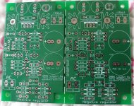
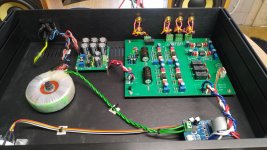
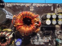
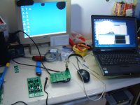
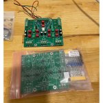
I got a PT Too for trade, but with issues. The last owner told me that it didn´t work, and I have now taken it apart.
It works, although not properly.


I know this doesn´t fix the bug, but:
-all electrolytic´s replaced
-rectifier replaced


Just to be certain the problem isn´t there.


But:

When trimpot on the right is turned to max and the trimpot to the left is turned to min, the motor runs quiet and as it should on 33. But when switching to 45 the motor just vibrates, not turning. When turning the left trimpot clockwise to 10 o´clock, the motor runs as it should, but now it just vibrates on 33. I have measured the two voltages at the motor (33/ 45) and it´s aprox 90V and 107V (when adjusted to the right speed with trimpot left). So the problem is that it´s not possible to adjust the trimpots to work on both speeds.
Anyone familiar with this?
Thank you in advance!

Attachments

  • IMG_3498-1.jpg
    IMG_3498-1.jpg
    671.2 KB · Views: 155
  • IMG_3499-1.jpg
    IMG_3499-1.jpg
    886.4 KB · Views: 129

Reverse engineering of famous chassis

Hello, everyone,
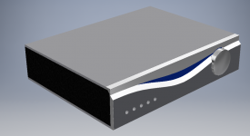
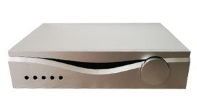
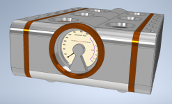
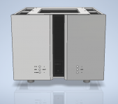
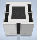
it all began at my friend’s request to do the CAD model and detailed drawings of the Audia Flight Strumento N1.
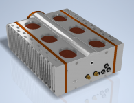
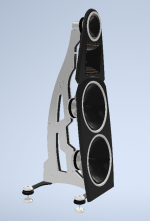
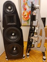
Over time, I’ve done the same for several chassis (Goldmund Telos, Vitus 103, D’Agostino Relentless, etc.) and Kyron Kronos body.
Some of them are adapted to the use non-original components (Strumento’s buttons, Kyron’s tweeter and mid-woofer) but otherwise my models are exactly the same as the original.
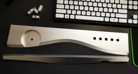
A few images of projects and, particularly, their realization, could be find below.
So, I can create 3D models, containing complete details and fastenings, of famous or less-known 😉 chasses. Having a model and drawings, you can produce them in any workshop.
I must add, reverse engineering doesn’t infringe anyone's copyright.

Attachments

  • AUDIA Chassy.png
    AUDIA Chassy.png
    341.4 KB · Views: 472
  • Audia detales.jpg
    Audia detales.jpg
    895 KB · Views: 475
  • Audia Flight.jpg
    Audia Flight.jpg
    24.7 KB · Views: 477
  • D'Agostino 2:3.png
    D'Agostino 2:3.png
    505.2 KB · Views: 462
  • D'Agostino back.png
    D'Agostino back.png
    414.7 KB · Views: 479
  • KYRON 3:4.png
    KYRON 3:4.png
    271.4 KB · Views: 204
  • KYRON .jpg
    KYRON .jpg
    192.3 KB · Views: 193
  • GOLDMUND.png
    GOLDMUND.png
    370.9 KB · Views: 209
  • VITUS.png
    VITUS.png
    238 KB · Views: 190
  • VITUS 3.png
    VITUS 3.png
    286.8 KB · Views: 178

NOS tubes for sale VT25, 6V6

Hi there,

I am selling the following:

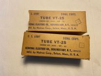
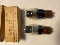
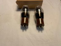
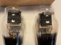
Pair of VT-25, NOS in original boxes. Asking $140.

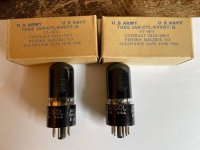
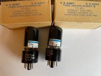
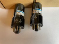
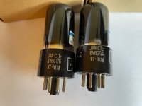
Pair of Jan-CTL_6V6GT/G. NOS in original boxes. Asking $80.

I will ship to USCON only for $15.

Attachments

  • IMG_6799.jpg
    IMG_6799.jpg
    395.1 KB · Views: 174
  • IMG_6800.jpg
    IMG_6800.jpg
    959.3 KB · Views: 174
  • IMG_6801.jpg
    IMG_6801.jpg
    874.1 KB · Views: 158
  • IMG_6802.jpg
    IMG_6802.jpg
    297 KB · Views: 153
  • IMG_6761.jpg
    IMG_6761.jpg
    380.2 KB · Views: 157
  • IMG_6762.jpg
    IMG_6762.jpg
    340.2 KB · Views: 63
  • IMG_6763.jpg
    IMG_6763.jpg
    283 KB · Views: 55
  • IMG_6764.jpg
    IMG_6764.jpg
    262.2 KB · Views: 60

Free To Good Home

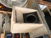
XKi for W5-2143 free to good home. I threw this together a while back and never did anything with it. Have not cut wings yet but everything else is done. Even lined with 1/2" felt. Would prefer DIYAUDIO member in DFW Texas area to pickup off my front porch so I don't have to ship. PM me if interested. Thanks.

Attachments

  • IMG_0014.jpg
    IMG_0014.jpg
    103.9 KB · Views: 499

DIY 12V Car audio power supply - troubles

Hello everyone!

It is the first time that I publish in the "power supplies" section.

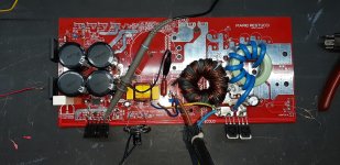
I am building a switching power supply to be used in the CAR AUDIO field, feeding it from the wall network, obtaining an adjustable output voltage from 12.4v to 14.4v (and beyond).


I made a project from scratch.

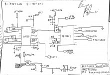
The power supply uses the SG3525 PWM controller which drives an IR2113S driver which in turn drives a pair of very powerful IGBTs.
The power supply is regulated, and keeps its output stable even when we are absorbing almost all the deliverable current (or at least it should) and through a potentiometer that adjusts the reference of a TL431 which in turn drives the LED of an optocoupler, I get voltage regulation and setting.


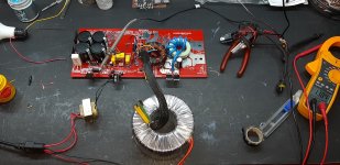
I made the PCB and installed the main components to start testing it, currently I have not installed the protections (short circuit and thermal) because I was interested in knowing if at least it did its primary job (produce enough voltage and current as I thought it would).

After doing everything, instead of immediately using the direct electrical network, I used a transformer to isolate myself from the electrical network and obtain a lower voltage to avoid disastrous failures, in fact, with 78Vdc on the large capacitors, everything was fine, the power supply produced the voltage desired, but obviously little current, in fact by loading the power supply with a 40w car bulb, the voltage dropped to 7 volts.
So, I used a bigger isolation transformer, and with 110Vdc on the big capacitors, still all right, and the voltage was also more stable, the current delivered, higher, and the voltage dropped a lot less (down to 10v).
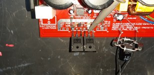
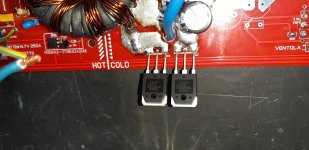
Everything seemed ok to me, there was no abnormal heating anywhere, so I switched to direct mains, first with a 220V - 40w incandescent bulb installed in place of the primary fuse and I got a lot more stability, but obviously when trying to absorb more current, the bulb started to light up and choked everything, then I replaced the bulb with a 47ohm 10w resistor, and I still got some improvements, then finally I decided to remove everything and install the fuse, now the problems started, because the power supply turned on without problems, but as soon as I connected the car bulb in output, one of the two internal diodes (of one of the 2 double power diodes) spontaneously shorted out suddenly, and having no protection systems I broke the two IGBTs and the driver accordingly.


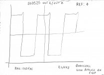
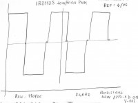
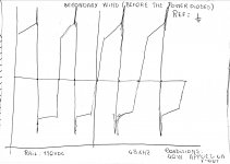
Cabbage! everything was going well, I would have also installed the protections and I could have fully tested my power supply, but something went wrong. Maybe the output filter? Perhaps the absence of Snubber on the output power diodes? It wasn't just a coincidence, because I fixed everything, and it happened again. I will post the schematic and some drawings of the waveforms that I saw on the oscilloscope before the failure, I have drawn them by hand, because it all happened yesterday, and I did not have the thought of taking pictures of the screen.


And of course, this is the videotest:
video

thanks to all,
Aids are appreciated!
Mario

Attachments

  • 20210405_221931.jpg
    20210405_221931.jpg
    418.7 KB · Views: 115
  • 20210405_221943.jpg
    20210405_221943.jpg
    438.8 KB · Views: 115
  • 20210405_221949.jpg
    20210405_221949.jpg
    391.7 KB · Views: 108
  • 20210405_221955.jpg
    20210405_221955.jpg
    458.2 KB · Views: 116
  • power transfer.jpeg
    power transfer.jpeg
    449.4 KB · Views: 111
  • pwm generator.jpeg
    pwm generator.jpeg
    348.4 KB · Views: 96
  • sg3525 signals.jpeg
    sg3525 signals.jpeg
    175.1 KB · Views: 87
  • ir2113s signals.jpeg
    ir2113s signals.jpeg
    209.3 KB · Views: 74
  • output signal before diodes.jpeg
    output signal before diodes.jpeg
    219.3 KB · Views: 70

hum resolved (hope it will be useful)

Hi,

The subwoofer I built (described in a previous post of mine) was starting to make an annoying hum.
The connection of the ground cable to the signal terminal was loose. Once the cable was fixed, the hum completely disappeared.
I forwarded this post because it was not easy to understand the problem as everything apparently worked.
I hope it will be useful.

Affordable(?) 3-way

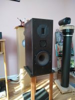
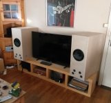
I’ve been intrigued with the Philharmonitor BMR reviews, but had no desire to part with that sort of money, so I put together a pair of 3-ways using Hivi RT1.3 tweeters that Santa brought, and my Nomex 6.5” woofers that I have had for ages. I did splurge and bought a pair of Tectonic BMRs for midrange.
I salvaged and reconstructed cabinets from some TL enclosures, 8” wide and 12” deep.
I went totally active with the aid of a couple of Minidsp 2x4s. I already had one serving my LXminis.
I picked up a a Rotel 100w x2 amplifier for $60 on CL to go along with the NAD 7100 and 2155 that I used with my LXminis.
Crossed at 900hz and 3500hz LR4 and with a little EQ, they sound really good.
Very impressed with the mid driver, which I played full range for a while before final assembly. Female voice is to die for.
I’m going to replace the woofers with Dayton RS180p-4 since the Nomex drivers belong in my 2-way speakers. The Daytons are on sale at PE and may provide a little more low bass.
Stay safe and keep building.
Peter

Attachments

  • 2FAD8131-E86A-4D92-87F9-FDCE018119DB.jpg
    2FAD8131-E86A-4D92-87F9-FDCE018119DB.jpg
    364.1 KB · Views: 122

general and specific amplifier building questions

Transformer secondaries are 24Vac, recommended fuses 6.3A slow blow, 25A rectifier, 10.000 µF first cap, 140.000 µF second cap.

The toroid only 300 VA for mono, no inrush current limiter needed.

For raw testing I would like to keep it as simple as possible.

So the obvious question is, can I turn that on without blowing something ?

Does it make sense to put a 5W 0,33 ohms resistor between the caps ? and will it withstand power on surge ?

I could cut the 140.000 down to 120.000

Linear L-240 recap and...

Hello team, I've lurked on various audio repair forums a long long time. I'm finally ready, (I think) to get involved in a recap.
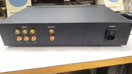
The subject at hand is a NZ made, likely in the 'heyday' for these vintage amps we know and love. Linear L-240 is the manufacturer and model.

The only 'data' I can find on this amplifier is here:
Happy birthday L240 • Heat • Public Address

Manufacturer may be mentioned here:
LINEAR Electronics Ltd Auckland New Zealand | Audiokarma Home Audio Stereo Discussion Forums

So the hopes of finding a datasheet are slim to impossible. Cool. Now I'm fairly new to soldering, but have access to a slick temperature regulated iron and I've been reading the how-to and tips for years. I think I'm ready to tackle a project. I also have a few friends who do this professionally, so I have the luxury of a few guides.

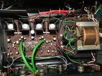
Now the amplifier worked momentarily, then began a feedback noise coming through. I suspect its the big capacitors in the power section, but as I'm learning, I would like to go through a full recap, to get a bit of practice in.

I've made a list of the capacitors. Are there any other things I should look at replacing? I've done some reading that suggests as long as capacitance remains the same, upping the voltage is okay. I've also read suggestions to keep the physical size of the capacitors the same, so that the legs pop in the circuit board without much mangling.

How would I go about measuring my current capacitors size to compare to the modern day offerings? Is there a physical sizing guide? Use a micrometer? Just a ruler for height / diameter? Are the physical sizes listed of the capacitors on mouser and such?

Any other challenges you wish to point out are helpful too.

I've included a couple photos of the project.

Dustin

Attachments

  • IMG_0412.jpg
    IMG_0412.jpg
    634.4 KB · Views: 327
  • IMG_0362.jpg
    IMG_0362.jpg
    1,019.5 KB · Views: 343

Nikko 220 mica insulators

Hello folks....I'm currently trying to refresh my Nikko 220 amp with a recap and I'm having a hard time finding replacement mica insulators for the power transistors. They must fit a 2SC2565 transistor as an example this being one of them. The old insulators measure 38mm long by 20mm wide with holes centred 25mm between. If I can't find new ones I'll have to clean and reuse the old ones but I'd rather not do that as one of the old ones is cracked. I've done a Google search and checked Mouser but can't pin it down to a correct one. Any help is appreciated.

Attachments

  • image.jpeg
    image.jpeg
    173.3 KB · Views: 131

European El Cheapo-ish build

In another thread (https://www.diyaudio.com/forums/tubes-valves/362926-stereo-tube-amp-build-advice.html) I asked about advice for a first tube stereo amplifier to build. Gladly a lot of people joined. After quite some switching back and forth and after extensive reading, searching and preparation I've just received my first goodies. Sourcing took a lot of time...
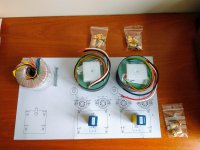
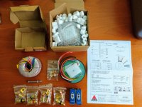
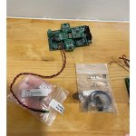
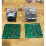
I chose some nice transformers from Amplimo; not El Cheapo. Not a dozen emails of every step in the delivery, but it was at my doorstep in no time. The packaging was top notch and they included a printed datasheet of the transformers. Perfect.

Attached you'll find a pdf with a lot of info I collected mostly from diyaudio threads and the original El Cheapo thread. It's not completed yet, just like the rest is not perfect.
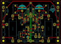
I've also made my first PCB, which I'm planning to send to Aisler for manufacturing.
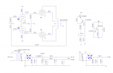
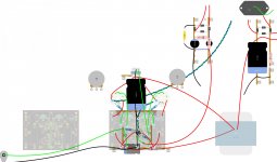
I've made the schematic in diylc as I've done before, but also in kicad once I thought a PCB would be nice. I also made a layout, not nearly as detailed as I would like, but I needed some hardware to make it more tangible.
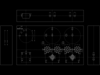
Lastly, I made my first CAD drawing in QCAD. I've had good results with just printing (previously using inkscape) that to scale and stick it to the chassis for drilling. I've tried CAD programs before, but they were not my cup of tea. Somehow QCAD seems a lot more compatible with me.

I plan to keep you guys updated with the build progress.

In the mean time, any comments are appreciated. It's my first stereo amp build, so I can use the help.

Attachments

  • IMG_20210203_140603879.jpg
    IMG_20210203_140603879.jpg
    978.2 KB · Views: 835
  • IMG_20210203_140009311.jpg
    IMG_20210203_140009311.jpg
    982.8 KB · Views: 786
  • ElCheapo.png
    ElCheapo.png
    320.5 KB · Views: 756
  • pcb.png
    pcb.png
    52.4 KB · Views: 789
  • ElCheapoSchematic.png
    ElCheapoSchematic.png
    156.7 KB · Views: 2,007
  • ElCheapoLayoutPCB.jpg
    ElCheapoLayoutPCB.jpg
    585.1 KB · Views: 614
  • ElCheapo.pdf
    ElCheapo.pdf
    482.6 KB · Views: 513

ARTA and USB interface

Greetings all,

I need a new microphone, and doing my due diligence, I came across a reference, claiming that certain measurement software, namely ARTA, has problems with USB interface, e.g., when doing averaging.

So I am now considering a non-USB microphone. As I understand, they need a phantom power and perhaps an amplifier.

Are there any stringent requirements in regards to the phantom power, e.g., noise, or will one based on 78XX series regulators work? And what about the amplifier?

I am looking at the EMM-6. Any other recommendation?

Kindest regards,

M

Parallel Primary Inputs of Two Different Signal Transformers

I want to 'split' a balanced line signal so I was thinking of doing the following.

Balanced Line Output > 2 x 10k:10k Transformers > Separate Outputs

The balanced line output would be common for the primary inputs of the two transformers.

  1. Do you forsee any issues with this configuration?
  2. Will the input impedance of my system become 5kOhm? If so, what will be the output impedance now?

Optical or Coax Input to DAC

I recently ordered a couple of DACs and I've only ever used the internal ones in various devices.

If I use one on my computer, I'll obviously use the USB input. But what about other devices that have both an optical and coax output. Is there any reason to choose one over the other?

I'm sure there are technical differences, which I'm interested in, but I'm mainly concerned with any audible differences.

Does it just vary depending on the particular DAC, in which case you just try both and listen? Or is there some consensus 🙂rofl🙂 that applies to DACs in general?

How to get rid of hum in a 6AS7 Headphone Amp

I am in desperate need of some help. I would be very appreciative of anyone who can help me solve a problem with hum.

First, some background. I built the following headphone amp and it works perfectly, no hum.

Nobsound 6N5P+6N11 Vacuum Tube Headphone Amplifier Board DIY KIT Single end Class A Amp|Amplifier| - AliExpress

Next I got more ambitious and built the following headphone amp:

A Single-Ended OTL Amplifier for Dynamic Headphones. – HeadWize Memorial

This headphone is almost identical to the first. The amp part I built is exactly as in the Headwize link. The power supply for the filament is identical to the one from aliexpress. The high voltage power supply is a custom based on a bridge rectifier, followed by 47uf cap, followed by 50 ohm voltage dropping resistor, followed by 330uf cap, followed by 50 ohm voltage dropping resistor followed by 47uf cap. I have separate transformers for both filament and high voltage. The negative of both transformers is connected to circuit ground. The high voltage supply is on a separate board. The filament supply is on the same board, but on the other side of the board. the filament transformer is about 2 inches from the 6AS7.

The problem is that the Headwize amp has a severe hum. The hum is the same no matter what the volume is set to. The hum starts about 30 seconds after power on. If i turn the power off, the music continues to play for a few seconds without any hum. Also, I tried using 4 D batteries for the filament supply and the hum went away.

I have tried everything I can think of to solve this problem with no success, so as I said in the beginning I would greatly appreciate any help I can get. I used high end parts in the Headwize amp, hoping to have a better sound than the aliexpress one.

Pcm2902 sound good!easy use!

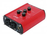
My friends told me he need USB DAC for computer record and KARAOKE with computer,I have use Roland UA-25ex many year,they have good parameter,
but I believe it so expensive.when my friend asked for me design USB DAC,I connect TI FAE,he suggest PCM2902 is excellent,cheap and good sound.So i works for it 2months,Test today ,sound excellent.I'll upload picture as attachment.
Friends on diyaudio have question why changing song there are POP sound,I found why!due to pcm2902 out signal need cap for dc isolation,you can try it once time,If you still have same problem,please mail me.

2type,one have 48v phantom power supply and combo XLR,other simple no phantom power only use XLR for banlance input and output.

Attachments

  • DSCF0607640480.JPG
    DSCF0607640480.JPG
    43.5 KB · Views: 384
  • DSCF0595640480.JPG
    DSCF0595640480.JPG
    65.7 KB · Views: 347
  • UA226404800.jpg
    UA226404800.jpg
    25.5 KB · Views: 355

Neurochrome DG300B Modified Build

I have had a set of boards for this amplifier for some time and I have finally started the build. I have some questions about the layout of the amp. Some background:

I am not an engineer (I am a nurse!) and this is my first project. Please do not assume that I know much.

The output valve will be the 6c4c which is a 7-pin version of a 2a3 and not the original 300B. I will be using the changes to the circuit detailed in Tom's build notes. I will also be inserting a Tribute AVC before the driver stage, making the amp a single input integrated. More on the AVC later.

Power transformer is a potted C-core from AEE. Output transformers are Tribute which I was very fortunate to get. Without testing my plan is for the Power transformer coils to be orientated front to back (so top to bottom on the diagram), OPTs left to right.

Top plate will be 450mm wide, 350mm deep. I have the aluminium already so not much scope for changing this. The Power transformer is 125mm square, the OPTs are 90mm square. The AVC is 50 x 50 x 100 and does not fit under the valves/PCB (amp becomes > 130mm tall which is too much for me)

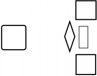
Below is a very simple diagram with a proposed layout. The rounded square on the left is the Power transformer. Two squares top right and bottom right are the OPTs. Rhombus represents the 4 valves with 6c4c top and bottom, input valves (6n6p) left and right, each vertex representing a valve. These components are all on top of the aluminium top plate. The vertical rectangle between the OPTs is the AVC which is under the top plate. There is not quite enough room to fit the valves between the OPTs (OPTs are 90 x 90mm, distance between outer edges of 6c4c valves in Tom's boards are 164.3mm, the long axis of the rhombus). Call this Option 1.

Option 2 is to leave the Power transformer where it is but flip everything on the right side so the valves are now on the right edge and the OPTs and AVC are now moved approx. 80mm towards the centre. This has the advantage of getting the small signal valves further from the Power transformer but it is not as aesthetically pleasing.

These two options have the advantage of placing the inputs of the PCB closest to the rear panel, keeping wiring short.

Option 3 has OPTs back in the corners on the right side but would rotate the valves through 90 degrees so the valves can now sit between the OPTs. This also rotates the PCB under the top plate so the signal path from the input sockets to the PCB is now longer. Option 3 maximises the distance of both OPTs and valves from the Power transformer and could be the most aesthetically pleasing with the possibilty to have the 4 valves symetrically arranged between the two OPTs.

Any obvious preferences in these 3 options or is there something better I have not even considered?

Attachments

  • Layout ver.1.png
    Layout ver.1.png
    7.7 KB · Views: 203

Universal Remote Power Supply

Hey team,

Quick question for those who have enough in the mind palace -

I am itching to produce a universal dual mono supply in a chassis - to be configured with umbilical to compact heatsink-ed amp chassis....

So, let's say I wanted to build on PSU to power the following (theoretically): Aleph J, M2x, and F5T builds.... 2x600VA yielding 32V rails? seems perhaps a bit high for the Aleph, but can be biased down... is it too low for the F5T?

I'd love this so I can continue to build and swap around without incurring higher amp chassis costs (bulk) as well as Transformers, and the like.

FWIW, I rummaged around the forum a bit, but there is since there are differing directions on rail voltage, maybe someone can chime a solve-all answer in.

Thanks in advance!

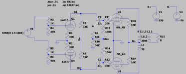
300B LTspice model, SE with A-A feedback

I have a 300B and it is very dynamic and so on. But amplification is a bit high.
The trannie is LL2752.

So up came the idea of a internal feedback (anode-anode, not across the output transformer.

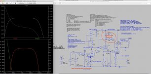
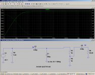
This is the basic idea:
Schermafbeelding 2019-03-19 om 15.46.58.jpg

The lower freq limit is lower than the -3db of the input (should be 25) but is modelled as 43 Hz. is fine with me. Lowering will give a little rise in the Va curve at the bottom end.
The high freq is quite high, at 80 kHz simulated.

Without feedback I get 8 Hz. And some 30 KHz. measured.
With different drivers I sometimes got 60 KHz measured,

any comments?

Attachments

Illustration of critical inductance

When using a choke input filter after a rectifier, some people prefer a multi-section filter, for example, L C L C: 5h-20u-5h-20U because it should reduce hum more than the same total L and C quantities used in a single section LC filter such as L C: 10H-40U.

Because the critical inductance depends on the minimum current to be drawn, it seems better for overall regulation when the minimum current is small, to use the singe section filter and put all the inductance before any capacitor filtering.

This would be for anode supply of class AB circuits having a low idling current, and in instrument-type regulated power supplies that have a wide range of load current. It should help to keep the no-load voltage from rising so much.

Parts on hand for this project are two 5H inductors and two 20uF capacitors. How to arrange them?

The chart shows data from PSUD for a proposed high voltage supply. The program was run using constant current loads from almost zero to 2A.

It shows that a single 10H choke followed by a 40uF capacitor gives better voltage regulation at lower currents (0.25A) than a two section filter mad of two 5H chokes and tow 20uF capacitors.

I hope this makes sense. I wish I had a 20H choke or higher that would take the current.

Attachments

  • lcrit.png
    lcrit.png
    18.5 KB · Views: 416

isolation/support for HEAVY Altec vot

Hello,
I am looking for some diy solution or non audiophile price ( so general purpose) so isolate my Altec Vot cabinets they are above 100 kilogram( 220 pounds) . I have no way to check the weight. So it could be a bit higher. Maybe i will add a bag of sand on top lol but i need something to give a better isolation than the rubber wheels.
Something like a ''pile '' of 4 square inch of 3.5 mm 1/8 inch thickness cork ''sheets '' like the ones on my wall or get some thicker cork panels normally used for temperature/sound isolation? I can make a sandwich of cork and lead sheets.
Any ideas are welcome.
Greetings,Eduard

Attachments

  • 20201125_160047kl.jpg
    20201125_160047kl.jpg
    464.1 KB · Views: 182

Replace ALPS Pot on Rega Mira

Hey all,
Did some digging online and I haven't come across a thread on this that I could find.


Anyone ever replace the volume/selector switch ALPS Pot on a Rega Mira series integrated? I've seen the scratchy intermittent switch is very common, but I've never seen an actual replacement solution.


Does anyone know if this would work?

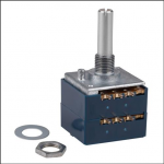
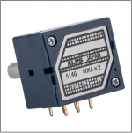
ALPS 50KAX2 50K Ohm Audio Taper Stereo Potentiometer 6mm Shaft


Thanks for any thoughts or experience!

Attachments

  • Screen Shot 2020-03-03 at 10.04.08 PM.png
    Screen Shot 2020-03-03 at 10.04.08 PM.png
    130.5 KB · Views: 151
  • Screen Shot 2020-03-03 at 10.04.20 PM.png
    Screen Shot 2020-03-03 at 10.04.20 PM.png
    194.3 KB · Views: 147
  • Screen Shot 2020-03-03 at 10.03.22 PM.png
    Screen Shot 2020-03-03 at 10.03.22 PM.png
    110.3 KB · Views: 132

MOSFET for capacitor multiplier

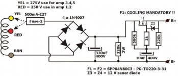
I plan to use the attached circuit from Menno van der veen's article on AudioXpress in the power supply of a single ended EL84 amp. The voltage after the rectifiers will be 320V. The current is around 100 mA max.

I found this MOSFET IPAN70R450P7S from Mouser. The datasheet link is here https://www.infineon.com/dgdl/Infin...N.pdf?fileId=5546d4625f2e26bc015f499adf55405f.

What are the specific requirements for the MOSFET in this circuit? Is there any concerns on using IPAN70R450P7S? Since this part has built-in protection diodes, do I still need Z3? What will be the voltage drop across the circuit?

Attachments

  • Capture.JPG
    Capture.JPG
    78.6 KB · Views: 1,715

Hypex SMPS400A180

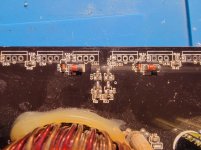
Hi. I have one monitor speaker that have 2 bridged UcD180 modules on 8ohm load for bass and 1 of same module on tweeter duty with this power supply.After 2 years of working ,last week on power up it wont work.As an electrical engineer myself i found that on power up 2 transistor of the supply board poppd up.The 2 in question are T7 and T14. The first is an smd part and i cant read it what it was,with some intuition and a little schematic i draw i think is an high voltage pnp part.The T14 is an npn KSP44.I already emailed hypex to ask what part number it is so i can change it myself and no answer for now.I must mention that the fast 5A fuse is working,the bridge rectifier too and the caps are good.Is only missing the low voltage startup part.
I ask is anyone have a module at hand if can make an macro picture of the tiny transistor to see the number printed.
Thank you in advance.
Daniel

PP amp driven with balanced input source

As a I am wrapping my current project (RH807 SE amp) I am thinking of the next project to build on this experience.

My DAC has 6.4V rms balanced outputs. So I was thinking of using this to design a PP amp without a phase splitter. Volume control would be done using a stereo stepped attenuator for channel. Would the topology a good starting point? Ignore the component values as I have not optimized the o.p. yet.

Attachments

  • pp_diff_input.png
    pp_diff_input.png
    46.8 KB · Views: 288

ECL82 Class-A amp - No sound

I built my first tube amplifier based on this schematic:
Single Tube amplifier
The amp powers on and I hear a subtly audible hum from the speaker that I would atribute to the power supply and heater wires.
I''m not getting any audi out, just a slight "hissing" sound.

I've modified the schematic below - I currently have the audio input from the pot with a 220k resistor in series and no ground. I'm thinking this is the issue, but not sure.

5W_ECL82_SE_amplifier | Zack Fedor | Flickr

Using a Triad R-23B power transformer
5k 8ohm output transformer from China (nice one though)
8 ohm speaker
USSR 6Mb8 tube, tested strong
1N4001 diodes on the rectifier
All componenets either new or in perfect working condition

I would appreciate any input 🙂

Communications Rectifier hot swap NPR24/48 information

Hello,
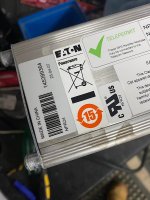
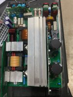
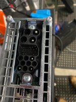
I have many NPR24 hot swappable rectifiers which were used in RF communication centres. These plug into a magazine and run in parallel to provide large currents for comms gear such as paging and LTE Transmitters.
Not Audio related however, these Switching power supplies are exceptionally well built and utilise ZVS topology as well as Power factor correction to minimise interference. The control uses a Atmel Mega32L and communicates using RS-485 modbus link (I think) communicates between the SM60 supervisory controller.

The NPR series where made back in 2007 by Powerware now bought out by Eaton.
I’ve contracted Eaton a few times regarding technical info, schematic and the modbus register map and as expected, got blown off. Can’t give information as its propitiatory line. Shame!
I feel there’s life left in these old girls and I’m finding plenty of used ones coming up on the web for not much at all. I’d like to save them from land fill or going to green waste and reverse engineering how to talk to them.

Question is, is there anyone with information about these such as register map for the modbus and schematic.

Somebody out there probably repairs them in early days.
Please PM if you can help out. Pictures attached

Cheers

Attachments

  • 54FBCCF6-22B8-4871-BF02-697AC64C4A26.jpeg
    54FBCCF6-22B8-4871-BF02-697AC64C4A26.jpeg
    160.7 KB · Views: 111
  • CAD1AEDA-00F1-4CA7-A547-7818E85D06D4.jpeg
    CAD1AEDA-00F1-4CA7-A547-7818E85D06D4.jpeg
    201.9 KB · Views: 106
  • 1AD89690-F507-4B5B-BF93-68F553B67813.jpeg
    1AD89690-F507-4B5B-BF93-68F553B67813.jpeg
    182.6 KB · Views: 104

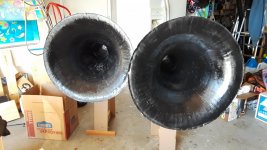
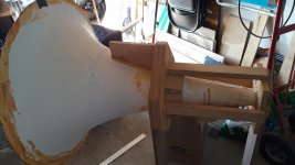
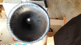
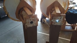
FS pair of paper mache 160hz tractrix round horn

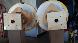
DIY paper mache round horn. Mouth diameter is 26 in. Throat is 1.5 in. Mounting flanges for JBL 2450 series compression driver included. Pin point stereo imaging even if put in corners. $100 for the pair. Local pick up only in Oceanside CA 92057

Attachments

  • 20210302_145405.jpg
    20210302_145405.jpg
    494.2 KB · Views: 406
  • 20210302_145434.jpg
    20210302_145434.jpg
    376.9 KB · Views: 372
  • 20210302_145353.jpg
    20210302_145353.jpg
    548.9 KB · Views: 375
  • 20210302_145247.jpg
    20210302_145247.jpg
    450.2 KB · Views: 354
  • 20210302_145458.jpg
    20210302_145458.jpg
    420.3 KB · Views: 372
  • 20210302_151923.jpg
    20210302_151923.jpg
    407.1 KB · Views: 223

Splitting the stereo cable to feed two amplifiers

Hello!

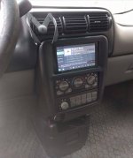
Not long ago I've removed the player in my car and put a Raspberry with USB connected SoundBlaster Play3 and a TPA3116 amplifier. The sound became very, very nice. Unfortunately I've physically damaged the amplifier and I have to change it.

I'm want to split the signal from the SoundBlaster with an Y cable to feed two TK2050 amplifiers that will feed the front and rear speakers separately.

What do you think will happen? Will the sound be better in terms of quality and power or it will be a downgrade because of the lower input signal?

Is there a chance to burn something? I'm thinking about a 7A or 10A fuse in front of the amplifiers. Will electrolytic capacitors do some protection without bugging the sound?

The cars is Chevrolet Venture with original speakers.

Thank you!

Attachments

  • rpi.jpg
    rpi.jpg
    233.7 KB · Views: 117
  • 2xTK2050.jpg
    2xTK2050.jpg
    212.5 KB · Views: 100

High impedance IN EAR headphone

Looked around in this part of the forum but could not detect a thread about high impedance in ear headphones.
Currently I am using a Sennheiser HD650 headphone for my headphone amplifier which is an absolutely great headphone. But it is an over the ear type and after listening during a long time ( 20-30 min.) it becomes a little bit uncomfortable.
So I want to purchase also a headphone which is an in ear type but all the types I see on the internet are low impedance around, 30 Ohms sometimes even lower.
Are there in ear headphones which have an impedance around 80 to 100 Ohm or preferably higher?

Sure Electronics AB32514 noise hiss

Hi

I have 2 sure electronics AB32514 amps and one of them has developed a nasty hiss at idle. Both amps were completely silent for a long time but one has now degraded. The noise is pretty loud, it is removed if I set the SW1 to off without the volume control board connected but gets worse once the volume control board is inserted. I also get a whistle when using the smps power supply but not on battery power. The other amp is silent on smps. If anyone has any suggestions I'd love to hear from you.

Did I just kill my Minidsp 2x4HD

notes : i have posted this in minidsp forum but looking at many threads without reply so i think i might get help here

I want to start my measurement and connect my 2x4HD and UMIK on my pc. Then I found for new firmware upgrade that are available for UMIK and start upgrading process, this is where i'm playing music at the same time.

But when UMIK firmware upgrade completed, suddenly 2x4HD stop working where no more sound and the LED does not lid anymore. I try to plug-unplug power connector and in a glance there is short lid from led when power is plugged but then no lid anymore

considering that i upgrade UMIK firmware where at the same time 2x4HD board is also plugged in, is it possible the software stupidly send the UMIK firmware to 2x4HD board that made it stopped working? Because the software also can not connect to the board to reverse the process, maybe is there any hardware reset button or pin?

Virtual ground isolation and pre-amp with current limiting resistors

I am building a phono pre-amp and i was toying with the idea of running it from the 18v DC supply in the turntable, which i have done a transformer swap on. Then I can just install it in there without using a new power supply.

So I built one of those capacitor and voltage divider virtual split rail.
I was testing - i have a +15-0-15 supply that makes this work fine. So I realize I'll have to isolate inputs and output earth with coupling capacitors. I did that and the phono signal still passes through and gets amplified.

Then I'm trying to run this NE5532 with this virtual power - using one of the rails as an input of 0v 15v - it measures (pos)7.5-0-7.5(neg) which connected up with the circuit and i've isolated the inputs/ouputs - linking their earth ... but now earth/0v is floating. So basically that kills the signal. Since they are isolated with coupling caps I thought, ok then I'll use the 0v that is actually now the negative rail for the pre-amp but its 0v otherwise as the 0v/ground and then i should have my input signal basically as before. Since 0v was ground before and it worked.

Doesn't work. Looking at the data sheet the NE5532 wants 5-15v +/- as min to max +ve and -ve supply. So I've got 7.5, should be enough to function.

My working circuit has 100 ohm current limiting resistors on the +ve/-ve supply of the op-amp which I do because it is one thing (along with bypass caps) that helps make it stable. Earlier I built unstable pre-amps and I copied this idea ... but maybe at this voltage that is a problem? I still have to test it like that ... but any ideas or circuit examples of how this kind of power supply changes a circuit and keeps the virtual ground isolated? Thanks - and sure, just link to another thread if I'm just repeating history.

Visaton BG 20 91L BR

Hi folks! I've checked some threads here about the bg-20 and thought I should at least share what I built afterwards.. This is my noob experience with the Visaton BG 20 full range driver.

I needed a couple of speakers for my newly acquired Xindak MT3 tube amp.
In waiting for a kit of better drivers I made a couple of BR boxes with these super cheap bg-20 in the mean time.. They are on 91 liter because that was what I had material for. 110Liter+ looked better in the simulations though.
They are tuned at 40hz.
I am impressed with the sound compared to the price and I will keep these speakers for daily listening on another amp when the new speakers are built.
If I build with bg 20 again I will probably add a couple of tweeters for more presence, but for daily background music it isn't needed.
Sorry for my crappy english..
Anyways..
Cheers!
//PacMandalore

Attachments

  • visaton bg 20.jpg
    visaton bg 20.jpg
    71.9 KB · Views: 525
  • Like
Reactions: bedrock602

Simulate an electret microphone LTSpice

Dear All:
I'm trying to simulate an electret microphone.

I'm using a 8v DC voltage source connected to an electret mic through a 4.4K resistor.

Is my simulation Ok with the 4.4K resistor in Parallel with the electret, or do I have to put the resistor in series?

Regards.
Alfredo Mendiola Loyola
Lima, Peru

Attachments

  • ElectretSimulation.jpg
    ElectretSimulation.jpg
    620.4 KB · Views: 2,040

Adding a pre-out main-in to a Rotel RA840BX4

Hello DIY enthusiasts,

I have an integated Rotel RA840BX4 amp that I used to enjoy a lot but had to put aside because it lacks pre-out and main-in connections. In my preferred setup I have a MiniDSP connected between the pre amp and the power amp to fix issues with the room acoustics and to serve as a crossover for my subwoofer.

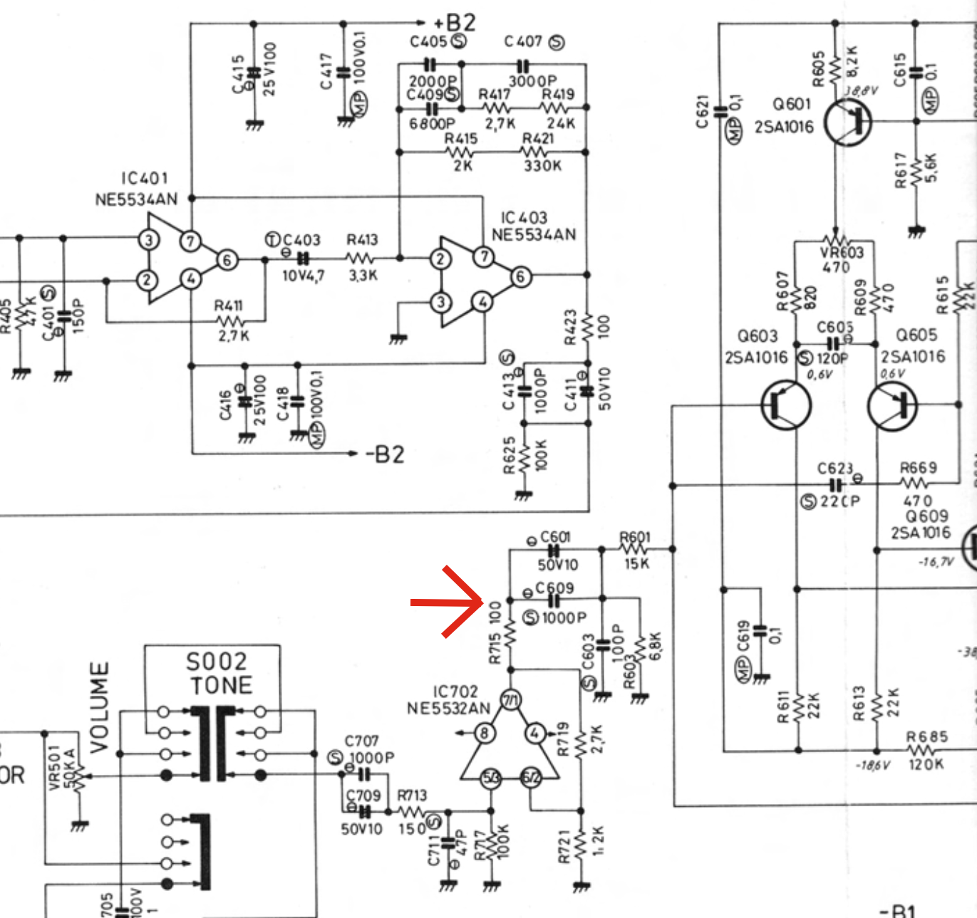
However, I assume that it might be fairly easy to add those. Looking it the schematic, I guess that I could simply add those by making a cut at the position I marked with an arrow (image below). That seems to give the desired low output impedance (delivered by the NE5532 OPAMP + 100 Ohm resistor R715) and high input impedance (15K Ohm resistor R601 + capacitors).

Would that work as desired?
Thanks! René

preoutmainin.png

High-Pass filter messing up the treble

Friends,

Summary: Highpass filter impacting signal above filtered range ... why?

I'm running a tri-amped + sub system, with electronic crossover. I still had the passive crossover lying about that I used in a previous iteration.

The problem is that when I'm mucking around with the electronic crossover (symetrix Jupiter 8) it's happened on more than one occaision that I flatten the curfve for the tweeters, sending full range signal down the line... oops. So far no blowups (tough little Vifa D19TD!), but I wanted to put the high-pass from the crossover back in the line to have some protection.

Only when I do so, the treble on low volume really suffers - that's 3 meters listening volume, and it's unbearable on quieter passages. The highpass I also notice really attenuates the soft background hiss that comes out of the headphones jack of my raspberry pi (waiting for the balanced audio HAT).

The electornic crossover cuts in at 2500Hz with steep 48dB LR filter.

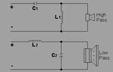
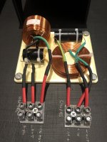
The passive components are per graphic C1 5.6uF L1 1.4mH. Only hooked up the high-pass.

I would have expected that the filter attenuates the signal, but it comes across really grainy, almost staticky, on low volumes. High volumes seem OK.

I've bypassed the coil and just hooked the cap in series, to same effect.

When I pull the cap out of the line, the signal comes through as it should, regardless of volume. I can dial it down until the treble gently fades behind the background hiss with my ear hard up against the 8 Ohm Vifa D19TD tweeter. With the cap in between, the background hiss is nearly gone, and the treble just stutters away.

From my calculation the filter should only take effect around 1800Hz and leave the signal above alone. What am I doing wrong?

I really want some protection (from myself doing stupid things) but I don't want to compromise the sound even at minimal hearing volumes (night time listening).

Attachments

  • crossover-2nd.png
    crossover-2nd.png
    15.1 KB · Views: 157
  • crossover-2nd-picture.jpg
    crossover-2nd-picture.jpg
    405.4 KB · Views: 148

aragon 4004 mk2 schematic needed

hello all- i have an aragon 4004mk2 that suffered a spike when the negative power supply rail on my preamp failed. 1 channel popped a fuse and i found a couple of driver transistors shorted and a shorted current regulating diode.
it looks like i need a schematic to proceed further.
if anyone out there can help, i would be most appreciative.

regards, leapingknome

Aragon question...

Hi!

After having sold off my Yammy M-80 quite a while back, and then an episode of lost funds with a previous diyA purchase, was finally able to get a reasonable deal on an Aragon 8002. Big difference in design/layout that I like; super clean. Nice noticeable improvement in sound quality.

Anyway, noticed one channel was running a touch warmer than the other, so I dived in and did the "check the bias thing). One channel read 18mv over the resistor, the other was ~30mv.

I re-set them to 10mv just as a starting base point (seems to be the magic number for a lot of amps. Runs cold and still sounds great. I know that this amp supposedly is supposed to run warm~hot, so the question is...

What is the ideal bias for the 8002?

Thanks.
bluesmoke

SMALL EXTRA: One odd thing (lucky me; like always with amps), I've noticed that when I've listened to the amp at low levels from a cold start, about 1 hour in the left channel seems to break up. As soon as I turn up the volume and run it for a while, things are fine when back down to quiet listening levels. Weird... It FEELS like a relay problem (me and relays... starting to hate them), but both channels seem to be making solid contact. Could still be a relay problem (oxide from arcing~ I can't see), but just wondering if there might be any alternative suggestions. Can live with the weirdness for now, but this is just shouting "fix me!".

Grundig NF-10 amp restoration

Hi all,

I recently bought a Grundig KS580 and am trying to restore it piece by piece. I will be posting my progress in case it helps others. [image]https://www.diyaudio.com/forums/attachment.php?attachmentid=934646&stc=1&d=1616398663[/image]. So far it looks like everything is working. Except... it looks like someone went through the amp and pulled out the tubes and output transformers. [image]https://www.diyaudio.com/forums/attachment.php?attachmentid=934647&stc=1&d=1616398663[/image]

I plan to get 2x ECC83s and 4xEL95 in place of the 2xELL80s. However, I could use help finding replacement output transformers to go with the EL95s. Here is the relevant schematic [image]https://www.diyaudio.com/forums/attachment.php?attachmentid=934639&stc=1&d=1616398230[/image]

I am new to analog electronics but here is where I am at so far:
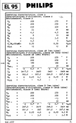
From reading around and peaking at the datasheet, a push-pull (I think that's what the schematic is) EL95 is 10kOhm primary impedance
[image]https://www.diyaudio.com/forums/attachment.php?attachmentid=934638&stc=1&d=1616398230[/image]
Speakers are 5ohm each and, if possible, I would like to wire additional 4ohm speakers for a 2-5ohm load.

Am I correct in that this means I need 10kOhm primary and ~4Ohm secondary? Would something like a Hammond 125DSE suffice? or are there better options?

Attachments

  • el95.PNG
    el95.PNG
    130.4 KB · Views: 586
  • Capture.PNG
    Capture.PNG
    674.1 KB · Views: 541
  • IMG_4314_rot.jpg
    IMG_4314_rot.jpg
    881.8 KB · Views: 549
  • IMG_4408.jpg
    IMG_4408.jpg
    823.8 KB · Views: 485

General question about mid and woofer selection for a three way

Hello, i am fairly new to diy audio, although i have done two projects.

This is concerning a general question. I have seen a lot of speakers using a 5.5 inch mid or mid woofer like the scanspeak 15m or 15w. With my current knowledge i dont understand however why most of these designs then use an 8 inch or 2 8 inch drivers instead of 10 inch drivers.
Shouldnt one be able to cross over at 220 hz lr2 for example? Or is this generally rather high for a 10 inch driver?

All the 10 inch three ways i see are using a 6-7 inch mid. And to me it seems this makes for problems concerning tweeter/mid crossover.

On a side note i am considering building a 3 way with the 15w and 25w8565 crossed at around 220 with second order linkwitz. This gave reason for my question...

Thanks in advance

Audax PR170M0 –100 dB or just *94 dB??

I’m looking for a pair of good, moderate price, high efficiency dynamic drivers, covering higher mid – lower treble, and the most often mentioned is the 100 dB Audax PR170M0.

Others are the Eminence Beta 8 and 10, JBL 2123, PHL 3451, Ciare PM250, some Supravox and the PHL 1040 & 1060 (yes different size > different response patterns).

Audax is now made by AAC, and the PR170M0 is back on the market for US $ 70 at Madisound:
www.madisound.com/cgi-bin/index.cgi?cart_id=1765800.22568&pid=107 with as before “100 dB efficiency”. .

I ran the Madisound specs through Unibox though, and the maximum SPL at 2.83 Vrms 1m was only 94.4 dB!
In deference to the driver, the nearest spec driver, the “100 dB” PHL 1040 came in at 99.4 dB, but that’s only 0.6 dB down, not 5.6 dB down!!

What’s happening, revised specs/ mistake at Madisound??

Thanks

Install Question

I have 2 questions been awhile since I did an install or messed with subwoofers .


Question 1: I’m rebuilding 2 DD audio sub woofers I had to order new baskets for the subs . My question is do I use locktite on the screws that are used to attach basket to motor assembly since the motors are heavy or is locktite not necessary?

2nd question : I’m gonna be running a 8k amp to the subs and 2 400 watt amps to the mods and highs . Question is I see 0 gauge , wire 4/0 gauge ect a lot of people say use 4/0 from front to back ect and from back batteries to amp use bigger wire and use a reducer is this really necessary or will 0 gauge wire be sufficient from front to back and back batteries to amps?

Also where the wires go into the amp do I just strip some wire and slide it into the terminal or should I use wire ferrules since a lot of people are saying to use them

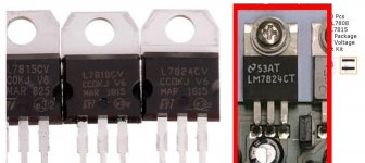
VRegs

Hi,

I thought I would post here as I'm looking for a couple of vRegs.
One, is the LM7824CT that is questionable in a R&S UPD.
Here is a pic of the three of the vRegs with the original
on the right in red.

These other vRegs are from a kit, linked here, LINK

What do y'all think?


Some reviews aren't so hot. They may be okay for
small one off projects, etc. But a Rohde & Schwarz,
UPD is high end and I'm sure their vRegs were Qualified.

Attachments

  • LM7824 Parts Comparison.jpg
    LM7824 Parts Comparison.jpg
    37.7 KB · Views: 200

Wanted schematic or photo overeem pamsonic 80

A friend of mine gave me an Australian “built in brisbane Queensland” amplifier.
Brand: overeem
Model pamsonic 80

The unit has failed as the preamp transistors had rusted the legs off and got lost.
I can’t identify the 5 of the 6 transistors on the pcb.
I think the first three are bc109.

Would someone have a schematic or even closeup photos of the pcb.

FS: Harbeth M30.2 40th Anniversary Edition

SOLD: Harbeth M30.2 40th Anniversary Edition

Harbeth Monitor 30.2 40th Anniversary Edition.

These speakers are in mint condition: 100% technically and 99% optically perfect. There is a very small scratch on the bottom where the speaker touches the stand otherwise everything is perfect.

With the special, limited WBT connectors! Kept in a smoke-free home. With original boxes.

High quality photos

Shipping within the European Union.

Price: 2800 EUR, open to offers

DIY Multi-Way for 300B SET

Hi -

I've built a few full range speakers and wanted to try my hand at something multi-way. I am using a 300B SET amp, and ideally want to build something that suits this well. Can someone point me in the right direction?

I listen to a lot of different music, but most of it is in the live music vs. electronic music realm. I ran a quick search but didn't see any builds. If multi-way just isnt the way to go with this amp, I get it, but if someone has done it well, I'd love to see some examples.

Best.

  • Locked
New speakers from Polk Audio

Polk Audio Reserve Series Loudspeakers Press Event - YouTube

Polk Audio’s Reserve Series Speakers Bring Legend Innovations At Lower Prices | Audioholics

https://www.polkaudio.com/en-us/reserve-what-better-sounds-like

Thanks to Sin Phi for the heads up. Apologies if this is a repost.

Lots of cool tech here to see. Internal resonance control, both in the cabinet as well as in the port, and a nifty woofer cone design. I'm surprised it's taken so long for big manufacturers to incorporate the third dimension, so to speak, to make cones stiffer, even after Fostex, KEF, SB Acoustics, etc. have demonstrated tangible benefits.

EDIT: Apparently most (or all?) of this tech was in the earlier Legend series. Oops.

ACA for audiophile friend as a gift?

Tube Headphone amp suggestions for audiophile friend!

Hello folks, I just got the email about the Sony VFET Amplifier and it rejuvenated in me this idea that I had before but I never reached out to get the info needed to help me make the decision and today I decided to do it. I appreciate your time and hope you can help me.

I have an audiophile friend. I thought it would be a cool gift for me to buy and build an amp camp amp and give it to him. I do not know though, if it would be "good enough" for him. It appears to me looking at the stats that it could be and I have faith in you and the people that like this amp. I just am old enough and smart enough to know what I don't know and try to get and use the wisdom of others when I can.

He has these Focal Stellia headphones (FOCAL - STELLIA - Acoustic sound purity, everywhere). Here are the specs they give in the docment:


He has others but these are his best ones, I believe. He even gave me his old Sennheiser HD 600s a while back (a few upgrades before he got these Stellia cans). Last I inquired (about a year ago when I thought of doing this) he used this SMSL SP200 (https://www.amazon.com/dp/B07ZJ6S1DX) headphone amp with them.

Here are some stats from that webpage:
Code:
Description:
The SMSL SP200 THX Headphone Amp is the latest product in the SMSL lineup with the top of the line audiophile high power grade THX AAA-888 technology. This technology allows for the highest fidelity with extreme output power and ultra-low crosstalk.

The front panel has XLR and quarter inch jack outputs, options for switching between different inputs, and choosing high or low gain. A detailed review for the SP200 and its performance is provided by Amir on Audio Science Review.

Features:
THX AAA-888 Technology
Ultra-Compact design - great for desktop
Toggle switch for operation, input selection, and gain control
Balanced stereo headphone output
Balanced stereo line input
High precision resistors for temperature stability
Pop-less design with high quality relays
Selected high precision low-distortion volume potentiometer
Full protection with DC, over-voltage, over-current, and short-circuit
Thermal protection on headphone amplifier
High-efficiency ultra-low noise power supply

Specs:
Inputs: Balanced x 1, Unbalanced x 1
Outputs: Balanced x 1, Unbalanced x 1
Output Power:
6W x 2 (16ohm)
3W x 2 (32ohm)
440mW x 2 (300ohm)
220mW x 2 (600ohm)
SNR: 130dB, A-Weighted
Output Noise: 2.8uV, A-Weighted
THD+N: -122dB, 0.00007% (1kHz, 32ohm)
THD+N: -117dB, 0.00013% (20 - 20kHz, 32ohm, -3dB)
THD: -125dB, 0.00006% (1kHz, 16ohm, -3dB)
Output Impedance: Near 0ohm
Frequency Response: 0.1Hz - 500kHz(-3dB)
Gain: Low(+6dB), High(+18dB)
Power Supply Voltage/Frequency: AC100-240V, 50-60 Hz
Power Consumption (EN60065): 24W
Power Consumption in Standby Mode: < 0.1W
Size: 160 x 149 x 73 mm
Weight: 772g
I realize he may not like the sound better and that these things are somewhat opinion and subjective but I just would like to make as sure as I can be that this amplifier at least would seem to be some sort of improvement over that one. It looks to me like it would be better power wise. I just don't have a good enough of a feeling to dive in. He's a logical person and he knows enough to give it time and let his ears and brain adjust and what not. I just want to feel more confident that this would be better at least in numbers and on paper that it would be a really good chance it would be worth doing and he wouldn't just appreciate it, (he would appreciate the gesture) but would actually love the product. If there is some other information you can think of that I could try to gather that would somehow help, I could do that too. I am hoping you can just look at it and say this amp would be a significant improvement and my hardest decision will be if he would like a silver or black face (I would prefer black so that's what he's getting - haha).

Thanks again for reading this and the time it would have taken you. Hopefully he doesn't find this thread and spoil the surprise.


Edit:


From the back and forth of this thread my purpose has shifted to wanting to find a tube pre-amp to make for my friend to test out against his Topping A90.

Driver Inductance vs Impedance Relationship

It has been a long time since I have worked with electronics and I am finding I have forgotten more than I remember. Forgive me, but I don't know how to word this question in a forum search to find an answer.

How does "Le" relate to... let's say nominal driver impedance? By this I mean, does a 4ohm driver with an Le of 1mH compare to an 8 ohm driver with double the Le? or am I getting that backwards?
Projects by fanatics, for fanatics
Get answers and advice for everyone wanting to learn the art of audio.
Join the Community
507,774
Members
7,888,020
Messages

Filter

Forum Statistics

Threads
406,217
Messages
7,888,020
Members
507,774
Latest member
pete2000