Input board w/rows of vias to reduce crosstalk... Good idea? Or bad idea?

I'm drawing out a line-level input board, for the back panel of my preamp, using PCB-mounted RCA connectors and switch/select relays. The board will have gound floods on both sides and I had this idea that it might be good to have rows of stitching vias along the left & right tracks to hopefully reduce crosstalk (see attached pic - top fill omitted for clarity). However, I'm now second-guessing myself. My 'solution-statement' question boils down to (select one):

  1. This a good idea and will it decrease crosstalk and/or provide other interference advantages.
  2. Meh, may not help, but probably won't hurt.
  3. Forget it, could cause negative capacitance (or other) issues. Remove them.

Other notes/questions: The ground planes tie all the input grounds and are single-wired back to the pre-amp's star-ground. Is it a bad idea to have the fills on both sides of the board? Also, the input-select relays will work the inverse way to most designs I see. The inputs are connected to the normally-closed contacts, so that all the non-selected input relays are energised, while the selected input relay is not - the idea being to reduce stray coil magnetic effects from the selected input. I know this is not a original idea, but thoughts?

Thanks

Attachments

  • vias.jpg
    vias.jpg
    200.3 KB · Views: 218

which headphones have the best noise cancelling?

Hello friends,
I am a person who loves listening to music, so headphones are indispensable for me. Because I have to travel, move a lot and be exposed to a lot of noise, I have to choose for myself a headset with good noise cancellation. However, I have used many different headset products but none have met my needs. So, I ask everyone to help me choose a good headset.
Thank you very much.

What to do with a fried JBL PB12

Well my JBL PB12 gave up after three years of careful service. Truly a bad design. Just starting buzzing late one night and then poof. The amp burned out, crisp.

So what can I do with it? JBL has offered to replace it for $250, about what I paid originally, so much for them and lousy customer service. I think I would prefer buying another brand after all I have read about JBL sub woofer products. No point in throwing good money after bad.

Any ideas? I have a modest system in a smallish room. Doubt I ever used the 250 watt capability of the PB12. I am fairly handy with a soldering iron, and building electronic things doesn't bother me at all. The down firing speaker is fine and enclosure is in good shape.

Thanks in advance...

Pioneer PD-7010

I recently acquired an old Pioneer PD-7010 and I'm running into a bit of trouble...It won't play disks.


Put a disc in the tray and hit the open close button. The tray closed.
The motor kicked on and returned the pick-up to the home location.
The disk set light came on, and the spindle started spinning the disc.

At this point, It's supposed to be reading the TOC...but...

The disk set light goes out and the disc spins down - nothing is shown on the display - still all zeros.

After dong a bit of ehem... RTFM....I found that this unit has a test mode button.

So....power button and test mode pressed simultaneously....and bingo test mode. yay!
and here are the test to perform:
An externally hosted image should be here but it was not working when we last tested it.


All operations here work except TRACK FWD and REPEAT. The focus actuator is moved up and down for both, but I don't see any light coming out of the laser diode. I'm assuming, I should see something right?

How best to repair my Infinity SL 10?

I've got a pair of Infinity SL 10 bookshelves. Nice cabinets but the speakers themselves are cheap, so I don't want to spend too much money on them. One of the little woofers came apart at the foam surround. It's a 5.25" woofer. I'm not looking for the best sound quality since these are inexpensive <$100 speakers in the first place. I think that the crossover point is 4.5khz. Overall, it's a 6ohm system.

Should I get a drop in replacement? Perhaps a cheap Dayton driver or some such? Any recommendations?

Or should I get the driver re-edged?

An Infinity replacement driver from Infinity will cost me $52, so that's a last resort.

Any help is appreciated! Thanks!

Dual voice coil Subwoofers

In moving recently, I discovered a trunk with two Volt 10" Dual voice coil bass units. They are 150 watt power handling and have low resonance 26Hz.
They are no longer made now, in as new condition, unused they would make a super subwoofer. If anyone is interested I would consider selling --- still have the originalconstruction article " Roaring Subwoofer ", printed in Electronics World, an 8 Ohm motional feedback design.

My first integrated amp build- where do I start?

I will try to keep this brief

My main listening room is my kitchen, and I am making some DMLs to hang from the ceiling paired up with a subwoofer to cover the full range. I have been cycling through some components but I was thinking about building an integrated amp with a custom enclosure.

Here is what I want:

  • Sources- Volumio stream (USB DAC), turntable (has built in pre-amp, NBD), occasional BT
  • Connection for DSP (don't know where it's best to run for least noise)
  • Volume controlled RCA outs for powered sub
  • Minimal interface- potentiometer volume knob, rotary source switch
  • Middle of the road interface- above + RPi touch screen for Volumio controls
  • Ideal interface- above with digital volume + source select and display integration with RPi touch screen

I think I could handle the middle of the road interface build myself... my main question there is what, if anything, I would need between all those sources and the input signal to the amp. I will be honest- I know basic electric circuit stuff and can solder, but I don't know anything about electronics. I'm a mechanical engineer, not an electric one. Anyway I see some places calling for a buffer to the amp and other places selling kits that feed RCA ins right to the board. I honestly don't know what a buffer is. Is one way better than the other? Will I have to do something about different source impedances? Will any old source switch work? Etc. etc.

I also have 4 channels @ 4 ohm, and the DMLs are admittedly a bit inefficient with the DSP changes. With this setup being in the kitchen, audiophile grade SNR is out the window, so I'm looking for recommendations on cost effective amp boards. I just found this for example, but I have no idea if it's worth buying or any good. The connections seem small for 2 (?) TPA3255s. So any recommendations are welcome.

Other question I guess is if anyone could recommend someone to build this for me 😀 I would just build the case as that would be a pain to ship.

Garage1217 DIY Headphone Amp Kits

Garage1217 gets a reasonable amount of love for the likes of the Ember, Sunrise, and Horizon. However, they're not mentioned too frequently in the do-it-yourself realm. That might be because the markup on the assembled amps is minimal, so the DIY kits aren't super cheap compared to the real deal (and Jeremy is an amazing builder, so it's hard not to buy them pre-built).

That said, the Sunrise and Horizon in particular are some of the best headphone/preamps below $1000, and especially under $500. I decided to do my part in service of the DIY community by putting together a video of the build process for the Sunrise III. It was great fun to build!

YouTube

Garage 1217 Project Sunrise III DIY Build Guide | Basshead.Club

Low frequency cutoff and feedback loop

Newbie here, i want to ask for clarification about what
impact the rc filter to ground in the feedback loop has regarding
the low frequency cutoff of the input filter.
Does it affect the cutoff frequency at all?


The datasheet for the lm1875 (and some other opamp's) mention
a higher cutoff frequency f=1/(2*pi*R*C) than the input filter.
But here
A Complete Guide to Design and Build a Hi-Fi LM3886 Amplifier - Circuit Basics
it's mentionend that the feedback loop cutoff frequency should be 3-5 times lower than the input rc frequency, and would cause distortion otherwise.

May someone enlight me? Thanks!

TU-8600S tubes tried and liked

I thought I’d start a thread on what tubes people have tried and liked in their TU-8600S. Some of these only have a few hours on them so I’m not sure if they need more break in time.

12AX7:
Mullard - My favorite so far. Good bass, nice warmth to mids and crisp highs. Have a couple versions, both sound the same to me, one used and one NOS. Good soundstage.
Telefunken smoothplate, used - a little less bass, not quite as much air. Good soundstage.
Amperex NOS - less bass than Telefunken, pretty good mid through highs. Need to listen to this one more.
Gold Lion NEW (provided by Victor) - high treble heavy, mid and bass seemed good. extreme detail.
Sylvania 5751 3 mica black plate NOS - pretty good. Slightly milder sound than Mullard. Used Loki+ to boost bass and this is probably my second favorite 12AX7.
Awaiting delivery - Telefunken ribbed plate, Valvo Herleen.

12AU7:
Telefunken smoothplate (used) - missing something in mid bass, not as clear highs as RCA cleartop
RCA Cleartop (NOS provided by Victor) - Best I heard so far. Excellent balance across frequency range and depth to soundstage.
Brimer - a couple different sets in the mail, waiting to receive. 13D3 and long plate.

300B (all provided by Victor):
Cossor black plate NEW - high treble heavy. Sounds pretty good. Good bass.
Cossor WE300B NEW - a little warmer in the mids, treble balanced a bit better. Good bass.


Favorite combo: 12AX7 Mullard, 12AU7 RCA cleartop, Cossor WE300B

Gear: Bluesound Node2i running Tidal and using Shunyata digital power cord ($135), TU-8600S, Klipsch RP-600M with GR-Research crossover mod. I have a Schiit Loki+ to balance out the frequency response as needed. It very slightly decreases the upper treble and soundstage, barely noticeable. I don’t use it with the favorite tube combo. It runs hot by the way.

Shipping an amplifier to a private address in Russia?

Hi all,

I wonder if you have an experience shipping an amplifier to a private address in Russia? From what I'm warned and read, Russian Custom has been extremely strict with items shipped to a non-business address. Fedex and DHL have warned me about this. I have an amplifier that a potential buyer is located in St.Petersburg. It'd be unfortunate if I couldn't ship this amp for him.

Is there any way I could get this through?

Thanks in advance.

Frugel-Horn XL - MN US

My first build, and sadly our living room was rearranged (for the better) and now I only have room for one set of speakers upstairs.

I am an experienced cabinet maker and these are made very well, no corners cut. Cat put a small dimple in one of the drivers but I am including a new one to replace it.

I was going for a darker grey-blue color, but they came out lighter and the front panel is blotchy. There is no finish, and I am happy to work with the potential buyer to finish them. Getting it back to birch would be tricky, so best options are probably a darker gel stain or veneer. If I keep them I will go dark stain and wipe-on-poly.

Asking $400 as-is, with three Alpair 10p drivers.

Attachments

  • IMG_20210617_112156782.jpg
    IMG_20210617_112156782.jpg
    480 KB · Views: 248
  • IMG_20210617_112132663.jpg
    IMG_20210617_112132663.jpg
    515.8 KB · Views: 249

Driving ESL with valves/tubes

Hi all,

I am new to this forum and I have been doing some research on building DIY electrostatic speakers. I have a questions that may be a stupid one but please enlighten me.

Electrostatic panels work by having the normal amp output of a few tens of volts stepped up to a few kV at the stator. My question is, if I'm driving them with my tube amps, which already put out ~400V from the output tubes, can I just step that up with a 10X transformer directly driving th stators?

It just seems a little "silly" for the voltage to be steped down through the amp OPT and then back up again through the ESL transformer.

???

Thanks...

Heybrook Sextet Mk 1V filler material & externalised x/overs

Finally I will fit the original transducers that came with these speakers, the mid and woofers are both SEAS and the tweeter is the long discontinued Tonegen ribbon.

When I removed the passive x/over I couldn't believe how all the components were crammed onto a too small plastic plate. The mid caps were hard up against the nickel plated steel screws😱

Worse was to come, removing the tweeters I saw that the chamber of both speakers had a bottom plate that some retarded knuckledragger had had various goes at with different drill bits and the ribbon cable had been twisted to get through the oversized round hole - as it was a ribbon cable why not make slot to take it tightly and fill with hot melt glue any small gap left so that the integrity of the tweeter/mid chamber was re-instated - beyond belief.

Instead I found a waterfall of way too much hot melt glue had been used. Half way down the bass chamber a big bracing bar of MDF is used across the sides allowing the bass to flow front and back - why wasn't this bracing bar heavily chamfered instead of hard edged?

The Heybrook Sextet have very shallow cabinets, perhaps this is part of the good sound. It occurred to me that if hard 90 degree corners are bad news why not use concave glued bracing on all corners, surely this is going to be better for sound quality and easy to implement during construction of the cabinets. I used hard wood concave bracing on all 4 corners. Much bigger concave bracing would be better and easy to do in constructing the cabinets.

Externalising the passive x/overs - Lying in a hospital bed it occurred to me that the soft oxygen tubing would be great to use not as dielectric but to absorb vibrations inside the cabinet. This is what I have used, drilling the back of the cabinets so that this is a tight fit for this tubing, maintaining the integrity of the both chambers. The actual x/overs have been installed inside ply rectangular boxes which hang from brackets which are open top and bottom to allow any heat to escape easily.

Filling - I don't know whether to use more filling in both chambers or stay with the existing. I have used bitumised sheet in the tweeter/mid chamber faces and in the upper bass chamber.

I have a lot of 'blankets' used when moving furniture, they are made of reused material which resembles felt I was thinking of using some of this glued to the walls of the tweeter/mid chamber and also on the bottom half of the bass chamber - any thoughts on this. if it doesn't work it can be easily removed.

With the integrity of the tweeter/mid chamber now corrected I expect a much more musical response from these two transducers and externalising the x/overs should result in much better clarity now they are not exposed to internal vibrations, again any thoughts from speaker builders welcomed.

DAC output buffer

Hello all,

I need your help in defining a small project.
I currently use a Raspberry PI 3B+, with an external cheap I2S DAC.
The DAC is a ES9023, without any output buffer.
The DAC feeds then my amplifier, a Technics SU-V9, and the following speakers (Grundig).
I'd like now to add a subwoofer to the system (I will build it, later on).
My idea was to build a dedicated board, wuith the following features:
- DAC output buffer, using an op-amp or discretes
- Subwoofer output, with low-pass filter (with tunable frequency) and variable gain
- Separate supply rails for Raspberry, DAC and analog part.

I have no problem for the last point, this is part of my work; I'd like instead to ask for your help for the first two points.
Do you have any suggestion, any schematic, for such stages?
Thank you in advance!

Ciao,
Giovanni

Non-linearities of cored inductors

I start this thread, because the subject of inductor linearity was raised in this discussion:
https://www.diyaudio.com/forums/equ...software-distortion-analyzer-post6199594.html
As I am also interested in the subject, I carried out some tests.

I tested three very different types of materials: a general-purpose manganese ferrite (grade 3H1), a VHF nickel ferrite (grade 4C4), and an iron-powder/polymer composite of unknown origin.
These are relatively old materials, but the data is still indicative, and more modern grades improve on saturation limit, temperature stability, HF behavior, losses -not on linearity-.
In the days of FDM telephony, linearity had some importance, but that's no longer the case.

I made the tests on X22 cores: they are convenient to work with, and I have plenty of them.
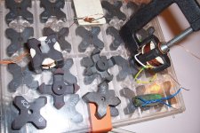
As I hate winding works, I used salvaged, already wound coil-formers as test windings.
This means that I didn't have the choice of the number of turns, but it doesn't really matter: the results have to be normalized anyway.

The tests were made for a zero airgap: what interests us is the core non-linearity for a given induction.
In an actual inductor, this non-linearity will become "diluted" by various factors, but by knowing the source value, it is possible to compute the non-linearity for any situation.
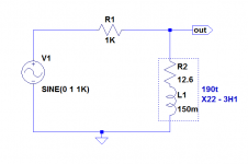
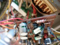
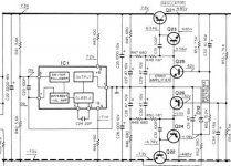
Here is the test-jig for the 3H1:

attachment.php


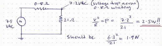
The 1K series resistor is calculated to be ~equal to the reactance of the inductor at the test frequency. It will be the load seen by the harmonics generated by the coil.
The test voltage was varied from 72mV to 2.2Vrms, resulting in a peak induction comprised between 1.293mT and 39.5mT.

Here are the results:

Code:
^B(mT)        k(%)

1.293         0.023
3.95          0.062
12.93         0.175
39.5          0.45

There seems to be a quasi-linear dependency of the non-linearity with the excitation level.

These raw figures will be reduced if an airgap is added.

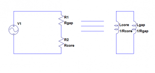
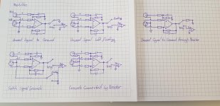
This is the equivalent circuit with an airgap: the reluctances on the left, and the electrical equivalent on the right.

attachment.php


It is obvious that by making Lgap much smaller than Lcore, the THD will be reduced in the same proportion.
Lgap can be computed : n²*µo*Ae/d (Ae= effective area, d= airgap).
The distortion will also be reduced if the excitation level is reduced.
It is counter-intuitive, but adding a gap will not directly reduce the induction: the induction formula does not include any magnetic parameter.
However if the gap is increased, the inductance will decrease and if the excitation voltage and frequency are kept identical, the current will increase, and the greater H will compensate exactly the increased reluctance.
Of course, in general the coil will be adapted to keep the same value with an increased airgap: this means increasing the number of turns by √r, and this will reduce the induction.

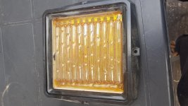
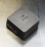
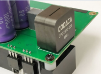
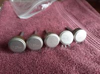
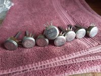
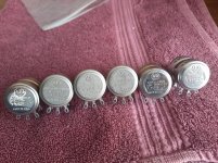
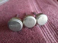
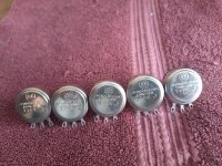
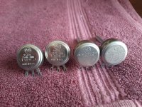
Here is a pic of the cores tested:

attachment.php


The 4C4 cores are clamped by a nylon bolt, but the 3H1's have a threaded insert and require an external clamp (or the proper mounting hardware).
The iron-powder core is an horrible kludge, more on that later

Attachments

  • JigMnZn.png
    JigMnZn.png
    7.5 KB · Views: 818
  • CoreNonLin2.png
    CoreNonLin2.png
    4.5 KB · Views: 771
  • CoreNonLin1.jpg
    CoreNonLin1.jpg
    378.1 KB · Views: 749

PASS LABS XA 160.8 100 to 230 volts

Hello everybody, I bought in Japan at the PASS LABS XA 160.8 monoblocks power amplifiers with a voltage of 100 volts,
I live in Finland and I need to set 230 volts,
I already had a couple of amplifiers from PASS LABS it was with universal transformers 115 and 230 volts ,
Is it possible to get service manual for our local service center
so that they can switch to 230 volts
Maybe somebody already have it
Thanks Alexander.

Attachments

  • PASS LABS XA 160.8.jpg
    PASS LABS XA 160.8.jpg
    517.6 KB · Views: 230

WTB FIRST WATT F4,5,6/M2/?, A Nirvana, H Badger AMP

WTB your DIY F4,5,6/M2/? First Watt, Alpha Nirvana, Honey Badger or other amp project (min 40w @ 3-4 ohms) in good working condition & made in accordance with Mr Pass or designer minimum specifications and genuine parts designation. In the spirit of Mr Pass sharing of his designs with diy community for non commercial use. Prefer West Coast or east of Rockies or Mississippi due to shipping costs. Please PM me. Thank you.

VinylTrak circuit boards?

Does anyone out there have a circuit board or gerbers for Bob Cordell’s VinylTrak MM stage? I came away from BA2019 with 2 pair of lsk489 courtesy of Linear systems. I was originally thinking of Bob Cordell’s RIAA pre-amp from the appropriate application motes, then I began to look at the VinylTrak in Linear Audio #4. At this time the learning curve for layout is much more than I’m willing to undertake. If there are gerbers available I would love to make a small run, or perhaps we could organize a group buy.....

Anybody?

Cartridge stylus tip radius and groove wavelength

Perhaps this is a basic question. Please follow my calculation:
The circumference of the innermost groove at a 60 mm radius is 377 mm. With the rotation speed of 33.33 the stylus travels 209.44 mm/s, that comes from 100/180 rotations per second, multiplied by d x 𝞹
A 20 kHz signal wavelength is 209.44/20000 = 10.47 micrometers on the innermost groove.
The stylus tip radius of my pickup is 16.5 micrometer (round tip), according to the manufacturer (Denon). My question is: how can the stylus follow the 20 kHz grooves, if its radius is larger than the wavelength? I can't visually imagine it.
Here I found some interesting overview, but still the question: is a round tip stylus unsuitable to play high frequencies?

Hill Plasmatronics: Bit by the plasma bug

Reading old threads, found some gems. It's looking like plasma will be a game changer.

Found Ulrich Haumann's site: www.plasmaspeaker.de
(Awesome guy) about many different plasma drivers, the he even makes parts.

hillplasmatronics.com Knocked my socks of at warp speed.

I've been studying the schematic and the patent and I'm excited. I'd be willing to go to a lot of trouble to get around inertia.

Hill did all the work, understood the math, (after some hours rereading the patent I don't). A horizontal output tube (6MJ6) regulates the overall current and audio is applied to the grid. 5 units in all, drawing about 1000 watts total. A high voltage PS flows through the discharge to the plate. simple and brilliant.

I plan to make a single unit. One tube, leaving the monitoring circuit out for the moment. I'll start with plain air, then see about renting a pony tank of helium. Balloon helium is out, since it contains some oxygen. (So kids don't fall out breathing it) Not sure if the Hill speakers preheat the helium, but in the patent he says doing so creates a sheath around the discharge, "which results in a spreading and stabilization of the plasma over a larger volume by lowering the density in it's outer regions".

If I can get it to work, I'll make more units.

Attachments

Troubleshooting a Yamaha RPU 100 receiver

I have 2 RPU100 receivers made by Yamaha for desktop use with PC's.
Sticking just one for the time being I had not used these for some time. But they are not in a basement or some place, just on a desk unused. Frankly I'm getting ready to sell them off since I use much less hi fi gear now-- just some audio from a separate computer setup.

After a lot of false starts I decided to test for trouble from the outside in. I have one test speaker on which I used the battery test to see if at least that was working. It is.

The next step in to receiver is the speaker connects. Those are the tab-type red/ black flip to contact and bite down on the wire through a small hole. I don't have a meter-- I'm not skilled at electronic tracing.

My question to begin with is: can those types of speaker connections go bad-- lose their "bite" on the wire or have some other problems. I have noticed the flip latch feels loose on one.

The receiver has USB to display the receiver on the PC and adjust with a mouse. It was a unique design but phased out by Yamaha. It has AM FM selectable from the receiver panel or on screen. Everything lights up.

I'm returning to the manual to find the RPU100 test mode: an on-screen display which will play a test tone.

But a brief answer just on the speaker in connecters described above is all I can ask for at the moment.

If this is an incorrect forum, please re-direct. In other days I never strayed far from the full range speaker forum.

LOT (46) Allen-Bradley Ohmite Potentiometers Pots Type J JS AB Ham Radio - 3.4 lbs -

$99 shipped US or best offer.

Attachments

  • 20210709_171940.jpg
    20210709_171940.jpg
    1.1 MB · Views: 106
  • 20210709_172347.jpg
    20210709_172347.jpg
    1 MB · Views: 99
  • 20210709_172651.jpg
    20210709_172651.jpg
    1 MB · Views: 97
  • 20210709_174445.jpg
    20210709_174445.jpg
    1 MB · Views: 93
  • 20210709_174605.jpg
    20210709_174605.jpg
    831.9 KB · Views: 89
  • 20210709_174902.jpg
    20210709_174902.jpg
    1,012.3 KB · Views: 66
  • 20210709_175029(0).jpg
    20210709_175029(0).jpg
    1,007.9 KB · Views: 52
  • 20210709_175128.jpg
    20210709_175128.jpg
    983.4 KB · Views: 58
  • 20210709_175234(0).jpg
    20210709_175234(0).jpg
    1 MB · Views: 53
  • 20210709_175536.jpg
    20210709_175536.jpg
    982.8 KB · Views: 70

Replacement for BEL PT4 & PT6 Needed

Hi folks,

I have a HMV STEREO 666 Record player. It is a 1976 model. It has a Push-Pull Class AB amplifier. Its two main amplifying transistors are...

BEL
PT4
AX6

and.....

BEL
PT6
SX5

I need to replace those transistors because they are gone. I have searched many places and they are not available locally. Can it be found anywhere or do these have any replacements? Thumbnails of these transistors are attached herewith....

Attachments

  • DSC_0033.jpg
    DSC_0033.jpg
    1,000.5 KB · Views: 414

Seas L19RNX1 2-way

Good morning, day or evening

Seas's prestige titan woofers are a rather interesting take on the modern style "small bass reflex enclosure, low efficiency, big bass" driver, and I would like to use one in a 2 way design. Being alu cones there's as per usual a nasty break up node to dodge. The driver I'd prefer is the L19RNX1:

H1878-08 L19RNX1

There is also the smaller 16cm with a slight higher break up but the higher sd and sensitivity is preferable.

Do you think crossing the L19RNX1 at 2000 Hz will be ok considering the breakup node? Will a 4th order be necessary to not make the node audible?

Help identifying Altec cabinet/model/plans

Long time listener, first time caller...

I've been looking to start an Altec project.

These cabinets have really gotten my attention.

They claim they're 820's, but the only info on 820's I can find is about corner loaded 821 or 820a/c. Those were driven with 2x803 for LF and 802/H808 for HF. Nothing about this style cabinet. They say the dimensions are Cabinet Dimension(each): 29 3/4" x 23 3/4" x 48"(inches), and the ~24" depth is very appealing to me.

Anyway, I'm looking for any info on these as I'd consider building a pair if I had more to go off of. Maybe this cabinet could benefit from reflex porting like the 817? Has anyone seen cabinets like this? Or similar plans?

If any of you are familiar with these, would you search for 803LF drivers? Would 416s or 515s "work"?

Thanks!
z

Here are the photos from the ad
URL]

Any builds using the Wavecor WF152BD03?

Hey guys hows it goin? I have a pair of these Wavecor WF152BD03 Wavecor WF152BD03 6" Balanced Drive Paper Cone Mid-Woofer 4 Ohm

Have there been any speakers built using these drivers that are any good? 🙂

I was going to try and design my own speaker using these and a decent tweeter, but this whole passive crossover design thing seems pretty complicated !

Available schedule - ELEKIT and Sun Valley

Due to the current shipping issue globally, we must ship all products via DHL or FedEx air. It’s a global problem, and it may get worse before it gets better.

Here are the tentative schedules to receive the following shipments from Japan :

1. ELEKit TU-8600S October 2021 $1,980.00
ELEKIT TU-8600S PRE-order August Production


2. Sunvalley SV1616D September 2021 $1,475.00
Sunvalley SV-S1616D [300B]


3. ELEKIT TU-8900 Late August 2021 $1.435.00
ELEKIT TU-8900 2A3/300B

4. Sunvalley EQ1616D Late July 2021 $900.00
EQ1616D Phono Amp

ISO driver selection advice for ~1 liter single driver desktop speaker with PR

Good morning,

I’m looking to build a small desktop set for work using this enclosure:

Denovo Audio Knock-Down MDF 0.04 cu. ft. Micro Bookshelf Speaker Cabinet Pair

It will be driven off of a small class D amp.

My main question is whether there’s something that can be used full range with a passive radiator such as this:

Peerless by Tymphany 830878 3-1/2" Passive Radiator

The reason I’m asking is because all of the builds I’ve seen for this box with a PR have a tweeter. I’m not completely opposed to using sealed it’s just that I would prefer to have more bass if possible.

I know this is all a lot to ask for (no sub, tiny box, one driver, literally any audible bass at low volumes) but my expectations aren’t that high and the competition is a JBL Bluetooth tube speaker which sounds quite bad but was free.

Thanks for any suggestions

Mike

NAD C 320BEE 230v to 115v Transformer Conversion Question

Hi folks,


Let me first apologize if this topic has been covered already as I performed a search on this subject and not much information specific to my question was returned other than getting a step up/down stand alone transformer.


I got this NAD C 320BEE 230v unit for $55 and would like to know if it's feasible to convert this unit over to 115v transformer.


Questions are?


Would I just need to get a comparable 115v transformer with a new cord and re-wire the unit internally to accept the transformer and would I also need to rework the power supply circuit board too.


I have some pictures of the internal 230v NAD branded transformer I can post if needed.

How does one cut ribbon foil to precise dimensions like the manufacturers do it?

How does one cut aluminum ribbon foil to dimensions with milimeter accuracy without going through a complex, delicate procedure? Is there some kind of equipment that can do this sort of thing? I have a lot of ribbon experiments I want to do and I require a method of making a sizable quantity of ribbon.

Thanks.

Frame grids and microphonics in guitar combo amp

DIY Audio was kind enough to remind me that it is my birthday today, so I decided to celebrate by starting a thread 🙂


My brief flirtation with a B&H FoS 626 (unconsummated) has left me curious about the PC97, of which this amp contained several. Looking at Merlin B's discussion about how he uses it in a pre-amp design, it looks like there should be a fairly smooth transition from the clean region where he is using it into high-gain, high-distortion territory. They are cheap, so I plan on experimenting.


The only thing that worries me is that this is one of them new-fangled frame-grid tubes, and may therefore be prone to microphonics. Which in turn led me to ask myself if there are ways to forestall this problem (in a combo design) by acoustically protecting the pre-amp stage(s): I'm imagining things like an isolated box-within-a-box, or even an "air chassis" where the tube sockets are hung from a butyl-rubber spider the way that microphones are often hung. Just curious to know if anyone ever went down this path to overcome microphonics.

Realistic mpa90 power amp are components melted

Hi All
Got this for a few quid but needs a recap but on the filter board pics attached the two capacitors polypropylene ones I think there caps look like the ics beneath them have melted ontop and caps attached to them.
So not sure if ics have melted or the caps have been attached to the tops of the ics with looks like tar.
If there meant to be like that is there a reason as normally the tops of ics are enclosed so can't see it being a type of circuit connection.
Any help most welcome.
If on wrong thread can it be moved over please.

Attachments

  • 20210511_113200.jpg
    20210511_113200.jpg
    948.7 KB · Views: 298
  • 20210511_113128.jpg
    20210511_113128.jpg
    785.5 KB · Views: 300

Anybody here know the (old) SoundLab Electrostatics?

Hi everybody-

I've been 'invited' (lol) to repair a pair of really old SoundLab (SoundLabs?) electrostatics. They are model R-1, I am told. Haven't seen them yet.

Apparently they work but at least one of them crackles. I find online comments that this is common but I'm not really finding specifics on a fix.

Anybody here ever crossed paths with these? Happy to hear any stories that might help. Thanks...

Revox B225 Spindle motor bearing

Hello,

I have a revox B225 that developed an issue. When I first got it it wouldn't open, and had trouble reading discs. I recapped all the boards, cleaned the laser lens, lubricated all that needed to be and it worked fine for a while. Now though when I insert a disc and press play nothing happens. The display indicates all 0's, the lens does its usual 3 ups and downs but the disc doesn't spin. Any ideas ?

New large JBL cinema speaker, the 3733

Plain and simple, I crave this, I want this...and it can actually fit in the common home at 0.28 M deep, 0.359 M tall, 1.52 M wide.
Odd thing is the LF section is at four ohms as we can guess, but the MF/HF section is at twelve ohms??


------------------------------------------------------------------------Rick....

Attachments

  • JBL big cinema spkr.jpg
    JBL big cinema spkr.jpg
    181 KB · Views: 270

Another Ground Connection Question

Hello,

First of all, sorry for another Grounding question. I've searched different topics already but for me the best solution of grounding is still unclear.

But lets start at the beginning. I'm currently trying to build my first partially self designed preamplifier. Therefore I'm having 5 Pairs of inputs with XLR and RCA each. Those XLR Inputs get converted to single ended by using Douglas Selfs circuit. Those single ended inputs then get switched by DPDT Relays and one Pair of single ended inputs is connected to my actual Preamplifier (attenuator first).

So now about my uncertainty: I've read so much and there are so many people arguing about the best way of switching inputs and connecting Grounds that I'm completly lost about which way might work for me.
For clarification I've created some drawings with the possibilities I've found, which is attached to the end of my post.

On the top left drawing the unused Inputs gets shorted to Ground which should prevent crosstalk/noise.
On the top middle drawing the unused Input hot signal is left floating, while on the top right drawing the unused input gets shunted to Ground through a resistor, also to prevent crosstalk/noise or prevent the connected cabel from acting as an antenna. In the bottom right/middle drawing the Input grounds are connected to something like a star point through a resistor, while in the bottom left drawing the Grounds are switched too by a DPDT relay to prevent Ground loops.

So could anyone tell me which way of switching the inputs and connecting the grounds I should use and why it is better than the others?

Thanks in advance and with best regards
DosenZorn

Edit: corrected some mistakes

Attachments

  • 20210706_133949.jpg
    20210706_133949.jpg
    689.5 KB · Views: 193

UTHAiM -- Just for Fun

UTHAiM stands for Universal Topology for Headphone Amplifier with Current Mirrors.

This is a project I built for fun, using components I readily had in my drawers. Surprisingly, amongst all the DIY projects I had done over the years, I had never used a current mirror before. It is no attempt to break record for lowest distortion. But based on this simple topology, one can try out a variety of configurations, and see how that affects the sonic results. Which is why it is a project, just for fun.

Of course it is only fun if you understand what you are doing. And therefore definitely not for beginners.

To support the GB effort of Nikon1975 to raise fund for Dave of Planet 10 which is seriously ill and in need of financial help, I made a “Planet 10 Special” edition of the PCB, and sent the Gerber files to Nikon1975. He will take care of everything of this charity GB from then on, with no interference from me. I only urge you to give him support over at the GB thread (to follow later at his convenience), for a good course. I have built two channels with negative feedback based on exactly the PCBs that Nikon1975 ordered. So we can be sure that they function as intended.

For technical questions related to the design, you are welcome to raise your questions here and I try to answer as I can. I also attached the basic Spice files here for you to play with. Please feel free to experiment in both simulation and in hardware, and share your experience with us.

Above all, have fun while supporting a good course. And of course you can also build this with a Vero board, as I did initially to proof the circuit principle.


Patrick

.

Attachments

Sun Bear cabinet for Tang Band W5 1611. nice!

I just finished these up and thought I would share the results. To my aged ears they sound very nice even witrhout filter. The imaging is exceptional' the tonality good and the apparent detail very good.
Because I wanted some more bass and to flatten the peak in he lower trebble, I whipped up the attached filter in Xsim. The other attached file shows the measured frequency response of the speakers; without the filter in green and with the filter in red.
Now for the part thet I wonder about. With the filter, on some recordings the sound seems more balanced and fuller with a bit more bass, but on other recordings the sound seems more detailed and transparent without the filter.
My guess is that this is because the more elevated trebble in the unfiltered mode is creating the effect, but I wonder if upgrading the filter with better than Dayton Audio components might give me a significant improvement and thus the best of both worlds.
In any event I feel this driver - cabinet combination is a real winner and want to give a big "thank you" to Scottmoose for the cabinet design.

Best,
Jay

Reduce the heat in class D Circuit

I starting this CPD2315S Class D inductor three months ago , it design with Litz wire which would solve heat problem in class D Circuit.

At first using 94-2 and 106-2 Magnetic ring core products is very hot while tried 7G23 but still have high loss , when turn the solution that with Litz wire CPD2315Swould solve the problem beacuse Litz wire would reduce AC losses in high frequency windings.

If the same situation you would try the same .

For more information of CPD2315S . https://codaca.com/en/product/458.html

Attachments

  • AMP.png
    AMP.png
    679.4 KB · Views: 164

Frankenstein Speaker - one good made from broken bits, bridging!?

Hello 🙂

I wonder if someone may be able to help me?

I have two broken items, one active PA speaker and one 4ch power amp, and want to make one working out of the two, and yes I believe they are somewhat different items but I am thinking it could work.

I have one Gemini GT-350, active speaker, and one Australian Monitor 200w/ch bridgeable 4ch class D power amp.

The Gemini, blew its fuse, I found one loose wire in side so re soldered it, still, blew the fuse, I removed and tried to test the power transistors, but only having a multimeter, I got confused, so ordered two replacement new ones, soldered these in and fuse still blows, so I removed the amp board from the Gemini, and fuse stays good.

I then remembered the AMonitor 4ch amp in the loft, I could use the power amp modules of this but, it distorts on all 4 channels, So I removed the input boards, assuming the fault affecting all 4 power amp modules would be on the input boards.

The pre, mixing part of the Gemini, which was wired to the Gemini amp board, I wired to the inputs of two of the amp modules of the AM power amp, bypassing the AM input boards.

Soak tested quietly for 4 hours, no distortion 🙂

The AM 4 ch amp could be bridged so running stereo 400w/ch rather than 4ch at 200w each. However this bridging option was switchable on the input boards that are now removed.

I am wondering if I can invert the signal from the Gemini so I can run, a pair of power amp channels, non inverted into one power amp ch1 and inverted into the ch2, and wire the XO to the +ve of ch1 and the +ve of ch2 to get the ch1 & 2 bridged. This is how the AM amp was set up, ch1 and ch2 could be bridged and wire from the +ves to the speaker, but that option as gone as the input/switchable boards are now gone.

I have done a little reading and thinking that maybe a:
http://www.samsontech.com/site_media/support/manuals/MCD2Pro_OM_5L_v2.pdf
would work with what I am trying to do, one input signal, would give two balanced signals out, which I can split, two pairs of non inverted and inverted... use these signals to bridge the 2 pairs of amps so one pair bridged for hi, and one for lo freq's

Crazy or possible?

Hope I am making some sort of sense...!?

Thanks for reading
🙂
Fingers crossed I am along sort of the right lines to get things up and running...

Yes my electronic skills and knowledge need some work!

🙂 Cheers

Oris 150 horns

I need to let these go, they have been languishing in my garage for quite a few years now.
More interested in cool audio trades than cash but would certainly accept good old American dollars as well, or a combination.
Oris 150 horns with stands, Lowther DX3 8” drivers, ported LaScala bass bins with 15” drivers from Charlie @ Azzolina Audio.

I will consider selling a Merchand XM26 tube crossover if interested party needed a complete package.
Interested in good quality DAC, vintage speaker drivers, any cool tube stuff., or even tubes, phono cartriges.
$1500.00 for horns and drivers
$2700.00 with crossover
Pick only, located in Texas, ( Houston area )

This photo is from about 8 years ago, if someone is interest I will unpack them and provide better photos

Attachments

  • 20210619_145013.jpg
    20210619_145013.jpg
    283.7 KB · Views: 449

FS: NHT XdS speakers

I have a pair of NHT XdS speakers for sale. Brand new, in the box, never been used - with - the matching Xd stands. Beautiful looking speakers. They use the Seas Excel W15CY001 woofers. These are the special dark finish.

PM me if you have a reasonable offer. Looking $600 for them.

Thanks

The Xd system was a fully active system, so these don't have crossovers in them, however, Rick Craig, John @ Zaphaudio.com, as well Jack Hidley - all have passive crossover designs for them.

Attachments

  • nht_xd.jpg
    nht_xd.jpg
    15.5 KB · Views: 141

Rate my 2-way horn speaker + subwoofer

Hi,

I recently finished my very first project that I want to share with you. Maybe you find some things I can improve. Parts I used:
-Faital Pro HF10AK in 12“ tractrix
-B&C 12PE32 in ~20L cb
-4x Beyma 12BR70 as subwoofers in ~70L (2x) and 80L (2x) cb
-DSP with 8 channels

Unfortunately I don’t have proper pics on my computer. But maybe you get the idea from my profile picture. Every driver has its own box. The speakers are placed in the corners of the room. You can find a sketch down below.
This is how the final measurements looks like:

attachment.php


Crossed @1,1kHz with LR 36db filter. This filter was the best sounding and also the best in the measurements. The compression driver is delayed due to the bigger distance to the mic. It was done by trial & error. With a delay of 0,6ms and an inverted midbass I got the biggest dip at the xover frequency. Not a single band of the EQ is left for the CD. But the final FR is pretty flat.

It was measured 1m from the baffle with an calibrated mic on the level of the CD (ear height). Because of the low height I get the reflexions from the ground prette early. I placed an absorber in front of the speaker. You can see the impulse with the window set here:
attachment.php


The off axis response looks like this:
attachment.php

attachment.php


The narrow dispersion of the horn works well with corner placement imo.

Low frequency integration was a bit tricky. With 1m distance to the mic the measurements go down to about 350Hz. Nearfield measurements are only valid up to 200Hz. But the nearfield measurement (and also the simulation) shows that FR of the 12PE32 is not flat at all:
attachment.php


Below 200Hz it’s loosing energy. First I crossed the subs at 80Hz with LR filters. But the measurements on the listening position with mic at 90° showed that the range of ~80-200Hz is lacking. This was audible too. I could try to push the low frequencies on the midbass. But since the xmax is limited (2,8mm) I decided to cross the subs higher.

The front subs are connected to same channel of the DSP & amp. And the back subs are connected to one channel as well. This is because I only have three stereo amps at the moment. So I can’t EQ and delay every single sub seperately. Here is a sketch of the room before I show you the measurements at the listening position.
attachment.php


The main speakers are placed on top of the front subs in the corner. I marked my listening position. The sub in the right back corner stands under a desk. I pulled it out of the corner a bit due to the legs of the desk. And I think this is one reason why got this response at the listening position:
attachment.php


The mains got a hp at 120Hz with Bessel 12dB. The front subs are crossed at 120Hz with Bessel 18dB. The back subs are crossed at 100Hz with Bessel 18dB and delayed a little bit. This was done by trial & error. With this filter setup I get pretty flat response from 20-200Hz. What I mean is that the sub frequencies and the kick bass are on the same level. Of course on every other position in the room the bass gets worse because of the eq settings and modes.
What was surprising to me is that I got this kind of bass response near the center of the room. In my first tests with every sub in the corner (especially the one in the right back corner) the bass was best sounding in the back of the room. Towards the center it got worse. But with pulling one sub out of the corner a bit the situation switched.

Here are some more measurements. The red curve is withouth EQ.
attachment.php

attachment.php

attachment.php


Things I didn’t measure or focus so far:
-Impedance
-Group delay
-Phase settings in the DSP (I just used delays to compensate physical distance)


What do you think about my project? Is the subwoofer integration done well? Or is it worth to try Geddes approach with different placement?

Attachments

  • Left Speaker.jpg
    Left Speaker.jpg
    161.8 KB · Views: 1,270
  • Impulse.jpg
    Impulse.jpg
    174.9 KB · Views: 1,121
  • Midbass.jpg
    Midbass.jpg
    133 KB · Views: 1,120
  • Off axis.jpg
    Off axis.jpg
    281.7 KB · Views: 1,081
  • Spectrogram.jpg
    Spectrogram.jpg
    269.2 KB · Views: 1,022
  • Sub EQ.jpg
    Sub EQ.jpg
    161.3 KB · Views: 1,071
  • Sub wEG.jpg
    Sub wEG.jpg
    174.3 KB · Views: 1,070
  • Waterfall.jpg
    Waterfall.jpg
    477.5 KB · Views: 1,050
  • 1,1khz polar map.jpg
    1,1khz polar map.jpg
    26.4 KB · Views: 1,143
  • Room.jpg
    Room.jpg
    54.5 KB · Views: 1,090

Heater windings are giving me too much voltage!

I am trying to use a old power transformer to breadboard some valve audio projects but the heater winding is give me too much voltage!

The calculations below don’t include the reactance of the winding at 50Hz, so it’s in the DC limit. But they indicate that I’m will likely dissipate way to much power in the heater filaments if I connect a valve (ECC83 triode).

Unloaded, I get 7.5VAC. So with a load, I will get 7.2V. Which means the filament will dissipate 2.5W rather than 1.9W.

Hopefully my calculations are off because at 50Hz the voltage will be reduced further by the reactance of the windings. But I’m unsure and don’t want to kill my tubes! Help!

Do I need a new power transformer? What would you do?

Attachments

  • 9C290031-3630-44DC-83BE-FB78C4CC229E.jpeg
    9C290031-3630-44DC-83BE-FB78C4CC229E.jpeg
    502.9 KB · Views: 379

Counterpoint SA-3000 Zener diodes

I've got a Counterpoint SA-3000 that was functioning but clearly needed leaking caps and some out of spec plate resistors replaced. In the course of preparing to do that job, I have found that the 3 Zeners in the power supply are so toasted that the surface of the bodies has degraded to the point I can't read any numbers.

I'd rather not pull these to test them out of circuit and risk damage; can anyone please help me with these Zener specs so I can order the correct ones?

Thank you very much,

Greg

Attachments

  • CounterpointZeners.jpg
    CounterpointZeners.jpg
    676 KB · Views: 236
Projects by fanatics, for fanatics
Get answers and advice for everyone wanting to learn the art of audio.
Join the Community
507,685
Members
7,884,222
Messages

Filter

Forum Statistics

Threads
406,035
Messages
7,884,222
Members
507,685
Latest member
EvenLouder