Hi fellow fullrangers.

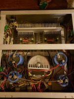
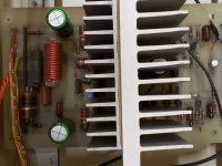
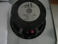
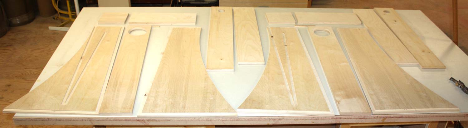
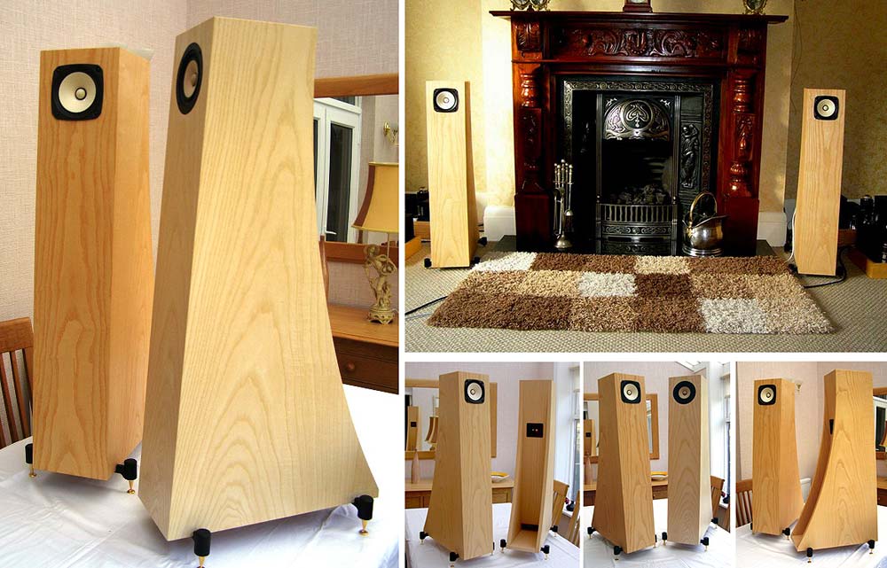
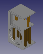
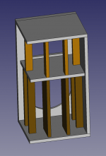
This is a small story of my experiments with a couple pairs of nice drivers from Mark Audio, namely their high-end Alpair12P and bottom-end CHN50, both of which I bought last year. I built a pair of small rear ported nearfield PC bookshelves with the CHN50s, and made a pair of onken-type speakers with the A12P, having 6 vertical rectangular vents in front of each box.
The CHN50's sound obviously doesn't compete with the paper-coned A12P's when it comes to overall quality and SPL, but these smaller alloy-coned drivers have something special going on in their frequency response. Simply put, I can play Any type of music and can sit back, relax and enjoy the music without ever getting the feeling of turning it down due to any unwelcome jump in SPL, starting from about 55Hz upto as high as I can hear. In other words, I absolutely adore these tiny drivers now for more than how they look! The frequency response is very near perfect for my ears. Here they are: (currently powered from a barebones 15Watt TPA3110D2 module)

Enter the A12P! The drivers sound truly beautiful hands down... but... (like that classy high-end girlfriend you can't get your eyes off because she's so this here and she's so that there but then she doesn't know when she switches from speaking to screaming when talking casually to someone standing one feet in front of her) the drivers have occasionally been a pain in my ears but no way I'm gonna let her go! It's complicated, and gets even more complicated when you realize that the published response graph in the datasheet has 20dB increments in the Y axis! Yes I missed that at first glance, second glance and third glance as well until someone told me to look close. You can see a couple pictures of the speakers in the fullrange gallery thread
>Here<.
So, for the last two months I have been playing with line level passive filters to control that dreadful midrange shout, and have finally reached a design that is simple, sounds good and sits comfortably between the preamp and the power amp. I may sound a bit hypocritical when I say that I don't want to spend on large inductors and capacitors after spending so much time and money into building these speakers, but it's just an honest bias against putting stuff between the amp and speakers, nothing more.
Now, Going over many different variations of the same basic design and listening to the results I noticed that while many of the iterations succeeded in taming the shout, sometimes they sounded really bad and a few times sounded really good. It's not about parts quality; on inspection, it became clear that for implementing the new response curve without sacrificing the music's soul, maintaining a relatively flat midrange phase is essential! It's not at zero degrees in the filter, but is more or less flat over the range of 100Hz to 1.5KHz.
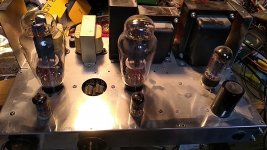
Two things I should mention. Firstly it is my guess that the A12P's peak/dip response may be affected by the amp that is driving them, in that the shout might not be too much of an issue with amps presenting a low damping factor e.g. tube amps, but all my amps are solid state and of high damping types. The drivers seemed to scream slightly lower with a resistance of 5ohms in series between them and the amp. Secondly, overall response with the filter added goes down by about 3dB. So for the same midrange SPL the volume knob may need to be cranked up more.
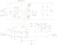
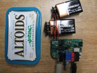
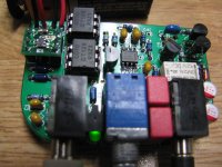
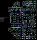
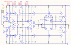
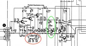
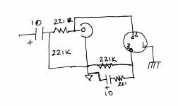
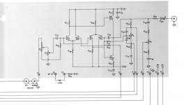
So here is the filter (texts explained below):
=
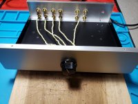
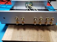
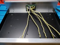
The contraption:
A bit of explanation:
As the filter is supposed to sit at the preamp's output, it is driven from a low impedance source. For different power amp input impedance the same filter response can be acheived by following the formula mentioned in the above picture.
"R AMP" is the power amp's input impedance in Ohms. Say it is 50Kohm (50000 ohms). Following the formulas in the picture of the schematic the values of the components can be calculated.
R1 = 50000 / 10 = 10000 = 10kohm
R2,R7,R8 = 50000 = 50Kohm
R3 = 50000 / 1.47 = 34013 = ~33000 = 33kohm
R4, R5, R6 = 50000 / 4.6 = 10869 = ~11000 = 11Kohm
C1 = 47000 / 50000 = 0.94 = ~1nF
C2 = 220000/50000 = 4.4 = ~4.7nF
C3,C4 = 1000000/50000 = 20nF
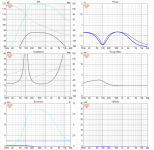
Using these values it will give a response very close to the green curve shown in the picture below.
Notice that the red curve is the result of the combination of component values calculated for 10Kohm impedance and it is very close to the green one. My application is the same. For driving the filter into 10Kohm input impedance of the amplifier I chose the following values.
R1 = 1Kohm
R2,R7,R8 = 10Kohm
R3 = 6.8Kohm
R4,R5,R6 = 2.2kohm
C1 = 4.7nF
C2 = 22nF
C3,C4 = 100nF
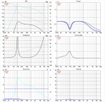
Here is phase response:
The design was not derived from calculations, rather the calculations have been derived from noticing changes in frequency response behavior with differing loads to the filter i.e. different input impedance of the power amplifier. The filter is sensitive to the load that is presented to its output. My main power amp has an input impedance of 10Kohms. So while experimenting I have been choosing values that give a preferred/equalised response only for that particular amplifier. If the design is built for an amp with a particular input impedance, and then it is driven into another power amp with a different input impedance, the response will change. But if your combination of preamp+amp is expected to be constant then that problem goes away. Besides, it is so simple and cheap that you can make one filter for each amp, with all the combos giving the same end-result.
Now, the A12P drivers have some fire in the trebles. So in case the mids sound a bit muted, the level can easily be equalised without too much affecting the overall response dips that act against the drivers' peaks. It can be done by changing the value of R6. Increasing its value will decrease the mid response and decreasing its value will increase mid response. Closing J1 will short the resistor, resulting into the green response curve. The red curve is the default response and the blue curve is with double the calculated R6 value. Changing R6 value will also change the overall response curve shape slightly and the main dip near 3KHz shifts a bit towards 4KHz. Shown in this picture.
If lows are to be kept same but you only want to change the mid+high level then R8's value can be played with. In this case the dip's level varies a bit, but doesn't shift much from 3KHz. Here is the response with changing R8 value.

Notice that all the above modifications also change the dip depth along with overall levels slightly, i.e. precision isn't great. But at the end it has brought the A12Ps to where I can sit with them all day every day without a hint of the shout that plagued the sessions before, for a cost of about 100 rupees (1.5dollars). They been playing with the new filter for more than a week now. The resultant frequency response the filter is giving in my room comes pretty close to that of the CHN50 drivers - in that the shout is gone and overall SPL balance from about 38Hz right up to the highs has been established. The most prominent of the peaks in the driver's response sit around 3KHz and the filter adds a -6dB dip there. There is another noticeable peak at around 800Hz but it's not as loud, so the attenuation is about -3dB. It's just a simple RC filter but as the effect has been well worth the effort for me, I thought it's worth writing a few words as well.
___________
EDIT:
As pointed out by XRK in the next post, the line level filter's response may have significant dependence on the preceding and following stages i.e. the preamp and the power amp's output and input impedance respectively. I admit I could have been more thorough in writing the original texts and sharing the graphs; so following the formulas I prepared a couple charts.
This chart is a bit tall. It shows the response of the filter with different power amplifier input impedance values starting from 5Kohms to 100Kohms. As can be seen, with appropriate values chosen, the frequency response is virtually unchanged from the lowest amp input impedance to highest.
The chart below shows effect of preamplifier output impedance. Obviously the response of the filter will change as the source impedance changes. But it's also very easy to solve this problem. As preamp's output impedance is changed from a low value to a high value, all we need to do is to decrease R1's resistance accordingly. In this picture one graph set is take with preamp's output impedance of 100ohm, and the other with 1Kohm. With R1 shorted in case of 1Kohm preamp output impedance the only thing that changes is total gain by about a dB. but the curve shape and positions of the dips/notches stays more or less constant.
So it can be seen that the filter is quite flexible when it comes to suiting different scenarios consisting of different sets of preamp+amplifier impedance values. The good thing about all this is that, the preamp's output impedance and the amplifier's input impedance are not reactive components unlike loudspeaker impedance, and are fairly constant values over their specified frequency response bandwidth. So when modding the filter for a set of pre+amp combo, we can be assured that the resultant response will be close to that with driving the filter from and to purely resistive source and load.
___________
Thanks for reading and I hope this info helps anyone who wants to experiment with the 12Ps the same way. Feel free to comment if you have suggestions and/or questions. I'm no expert in designing filters and would love to learn if the filter can be modified further in ways that makes it more effective without getting too complex.
p.s. you can see all the pictures in this google album -
Alpair Filter
shaan


