Sun Audio 2A3 Modifications

Hey guys, just built the sun audio 2a3 using all Hammond transformers. I like what I'm hearing (clear/transparency/detailed) but I'm looking for a more warmer/meatier sound. Any advice?

Also there's too much gain, my volume pot is super sensitive! Should I convert the DC 6sn7s to parallel?

Any help would be appreciated, Thanks!

Attachments

  • Sun-Audio_VT-2A3_3.jpg
    Sun-Audio_VT-2A3_3.jpg
    73.1 KB · Views: 1,216

Feeling happy: fixed my Hitachi HA-7700

Hi everyone. I wanted to post on this forum as it will get "out there" on the web, and this is probably the best forum of the lot! This is my first post (I've been lurking with an account for a while), so thanks for having me.

I've had an old Hitachi HA-7700 up in the attic on the "fix or dump?" pile and finally got around to looking at it for a weekend project. The symptoms were originally that the protection relay wouldn't pull over at switch-on. When it occurred about 8 years ago, I did a quick measure of the MOSFET voltages, and one channel was clearly broken - with the sources sitting at something like -20V.

When I did the same test yesterday, both channels were displaying odd, but different, MOSFET voltages. I trust my younger self enough to believe that in those 8 years in the attic, the other channel seems to have gone wrong too.

A look online and I noted that a number of German forums mentioned that the "fuse resistors" aged badly - so I tested them. "Aging badly" is something of an understatement! All but two in the Main Amp section had gone open-circuit and the other two had gone high in value. So I had to discharge the reservoir capacitors, disconnect and extract the whole Main Amp section. (After carefully photographing and documenting the connections.) This wasn't too difficult to do. I had to "unwrap" the wrapped wire connections, then remove a few strategic screws and the whole Main Amp unit could be taken out of the case, along with the heatsink. Desoldered the MOSFETS carefully and the Main Amp PCB could then come away to allow me access to the underside of the PCB.

The MOSFETS all checked fine. Phew! I replaced all the "fuse resistors" with 0.25W metal film units - checking beforehand that none were carrying heavy current. With the PCB on the bench, all the electrolytics on the board were also replaced. I checked all the semiconductors in-circuit and they seemed fine. (There is only one IC in the unit, see later...)

Weirdly, one of the fuse resistors was actually incorrectly wired, which still has me beat - it connected to a pad which went nowhere, which would have impaired the function of the protection circuitry, but clearly it must have still worked "well enough" to have passed original Quality Control - I put my replacement in the correct holes. Then I remounted the PCB on the heatsink, resoldered the MOSFETS, remounted the whole Main Amp block in the case and reconnected all the wires to the correct tags, soldering them this time, as I don't do wire-wrap.

Before applying power, I then took another look at the schematic/circuit diagram and started to wonder about the Regulator/Protection IC board. Since I'd already gone to a fair bit of trouble, I decided to give that a once-over, in case there were any poorly-functioning electrolytics there. A few more hours were spent replacing all the electrolytics on that board and checking the semiconductors (all checked out OK). Obviously the one thing I couldn't check was the IC - an HA12002 8-pin SIL unit, almost certainly now unobtainable, or at a high price. "Well, let's hope..." Given that nothing else on the board seemed to be malfunctioning, my efforts were simply being cautious about old electrolytics.

So came the big power-on. I removed the links to the pre-amps, put a voltmeter on the MOSFET sources (which are the output of the amp) - held my breath and switched on. No bang! Then, after a few seconds I heard the delightful sound of the protection relay, which was the first time it had pulled in at least 8 years. The source voltages were each about 100mV off zero, which is about right. I didn't bother checking the idle current, as I hadn't replaced any semiconductors and the resistors I had replaced were all the same as new.

Next I checked the Amp on load, it works fine.

I have decided now that I have a working Main Amp again, I am going to service the pre-amp (including doing the requisite electrolytic replacements). Given the high quality nature of the unit, I think it will be worth the time.

Hope that's a help to someone in the future with problems similar to mine - bottom line, replace all those "fuse resistors" and be very careful that you document your dismantling and be very careful to preserve circuit integrity. I'm experienced in electronics build and repair, and it was still quite a big job. But worthwhile...

Paul Roberts (UK)

PSU ground is some 84V DC above Safety Earth - is this normal?

Hi,

The Serj Amp 1 project I did a few years ago has been working fine (besides a hum, so maybe ground loop), and continues to do so.

I was looking into setting up a test PSU for my next project, and noticed there is some 84V DC offset relative to safety earth (the Earth pin on the UK plug).

I just tried instrumenting my Serj Amp 1 (which has been working fine) and that also has the same, IF and only if I unplug my LM3886 boards from the power / or if I unplug the audio input internal connections.
As far as I can see, doing either of those (unplugging my molex for the power / unplugging JST for audio) disconnects the ground conductor that appears to be pulling the PSU ground to 0v (w.r.t. safety earth).

I have to get some pictures of the board setup (to post on this thread), but it seems like PowerGround net is being pulled to safety earth via the Rgb1 resistor so that the SignalGround is connected.
SignalGround may be making a connection to the metal case (which IS tied to Safety Earth) via the RCA connectors (they do have nylon insulators, but might be making contact).

Rather than leaving PowerGround floating, what's the appropriate UK-specific advice on equalising the potential difference between my device and my PC that's connected to it?
Surely my PC's audio line out is earthed to safety earth, and having this 84V would cause a current draw and power consumption?
Thank you in advance 🙂

Attachments

  • psu_stage.png
    psu_stage.png
    15.5 KB · Views: 60
  • amp_stage.png
    amp_stage.png
    30.8 KB · Views: 58

Audio compressor question

Hello. I am assembling a homemade two-way speaker with an active crossover and would like to add low-frequency boost to achieve interesting sound at low volume levels. Having studied the topic a little, I came to the conclusion that I need a limiter or a compressor. Inspired, I turned to a group of audio enthusiasts with a request to help find a simple compressor circuit. This is a circuit on an optocoupler and a dual operational amplifier, quite simple. I was able to make a primitive printed circuit board and began testing it with only a superficial understanding of how to set it up. After fiddling around for several days, I realized that nothing was working. Since the compressor is quite slow and affects the entire incoming signal, there were volume jumps or a drop in volume in general if a long release was established.

In general, I am interested in portable speakers and have tried many different ones. The models that stood out most were JBL and Harman/Kardon. Their peculiarity is that low frequency compression occurs without any noticeable effect on other sounds, and to be honest I don't really understand how they achieved this. Ideally, I would like to understand their signal processing algorithm and assemble something similar for myself. Maybe someone has studied this topic and can tell me more?

I make some measurements harman/kardon speaker amplifiers:

Attachments

  • HK luna amplifier with different lenght sweep at 100% volume.png
    HK luna amplifier with different lenght sweep at 100% volume.png
    243.2 KB · Views: 31
  • HK luna amplifiers 10-100% dB scale.png
    HK luna amplifiers 10-100% dB scale.png
    537.9 KB · Views: 32

Greetings from Strasbourg, France

Hello to all,

I'm based in Strasbourg, France and I'm interested mainly in restoring vintage Dual hifi and Tascam recording equipment. I have only been restoring stuff on and off over the past 10 years, so I have much to learn. Prefer the older pieces of gear as they seem simpler and I can get my head around the electronics! I have brought back to life a Tascam 38 tapedeck, M35 mixer and a few other bits and pieces - dreamed about having them in a home studio when I was a teenager. It's only taken me about 40 years, but I'm getting there. Managed to build a functionning (albeit imperfectly) RCA BA-2C preamp for some ribbon microphones I have - just need to deal with the source of an annoying background hum...like I said, I have much to learn...

Currently working on restoring an old Dual CV40 amp for use with a Dual CS510 turntable (equipped with Shure M95 cartridge). Love the look of the old Dual equipment! I intend to use them to play my LPs.

Look forward to exchanging with you.

Martin

Op Amp / Tone control question. Palladium/Lotte Prestige amplifier

Hi,

so I have this amp to fix - Palladium Prestige (aka Lotte Prestige, also sold under other names).

I can't find a service manual anywhere.

The amp has distortion on both channels after a while. It is OK when set to DIRECT (bypass bass and treble controls). The fault is in the pre-amp.
The pre-amp has 2 NJM4558DD. One for each channel and half of each handles the direct path and the other half the tone control part. There is high voltage on the outputs on the non-direct side. And after a while the capacitor on the output of the preamp can't filter it and the sound is distorted.

The input is the same for direct/tone control. I have drown the schematics of the circuit around the opamps.

The opamps themselves work fine, I have replaced with new ones. If I remove the connections to the bass and treble pots, the issue remains. So the only difference really is the circuit around the opamp. I can get is more or less stable and output under 50mV when i replace the 470kOhm resitor with 166kOhm. It works fine, but does not stay on one value like the direct side.
As far as I can see the ground is connected where it should be and the components around test ok. Which brings a question why is it not working as the circuit was designed like this and should be working🙂

Attachments

  • IMG_20250215_214459.jpg
    IMG_20250215_214459.jpg
    156.6 KB · Views: 75
  • IMG_20250215_214731.jpg
    IMG_20250215_214731.jpg
    537.8 KB · Views: 78

Putzeys Balanced Preamplifier with MUSES72323 Volume

Here is a balanced volume control/ pre-amplifier based around Bruno Putzeys excellent design. In this instance, the original Baxandall volume control section is replaced by the MUSES72323 digital volume controller. The MUSES chip provides two digitally controlled elements
  • firstly a simple resistive ladder network to act as a straightforward attenuator with steps of 0.25dB and can be set to MUTE, then in 0.25dB steps from -117.5dB up to 0dB
  • secondly, a resistive network to control the pre-set gain of an externally connected op-amp as a non-inverting amplifier. Gain can be set from 0dB up to +21dB in 3dB steps
Apart from the connectors and most electrolytics, the circuit board components are primarily SMD. The SMD resistors and capacitors are all 0805 size, the op-amps are in SOIC-8 packages. The smallest item is the MUSE72323 device which is in a SSOP-32 package. The layout is relatively lightly packed so that it remains straightforward to assemble.

The MUSES 72323 digital interface uses SPI format data and it can easily be controlled from an Arduino, ESP32 or similar.

Attachments

New Hifi Engine website

Folks, I am in process of making a website to replace HiFi Engine and looking to recruit help. My issue with that site started last week while visiting a local friend also in the Vintage repair business. He was at he moment fixing a fisher receiver, he attempted to download the manual from HiFi Engine it didn't work, not thinking about it I volunteer to use my login to see if would work (or if it was a temporary website issue, etc) and now we are both banned for life. My colleague (a 65 year old man well respected in the southern Ontario audio community with 45 years expience & 20 year speaker designer at Angstrom Speakers (when Higher Fidelity Company own it)) was using the site day prior with no issue, that was his first download that day. He & I were both long time users and never believe we violated any rules & respected the site's rules. Apparently they don't respect users and banned them for what ever reason they feel. So be it, don't care if the owner is that petty its his site to be petty about. I have registered HifiEgine.ca and have approx 100g of schematics to initially populate it with. I plan to offer the same upload/download ability but what I would like to change is obviously the "banning for life" aspect, have a method to contact me if there is a problem, I don't care if users have more then one account, larger download quota per day, and if someone wants a copy of everything on site they can cover my cost to ship a usb drive to them, not have the pfd's password protect so user can clean there copy up should they so decide, (again another of HiFiEngine.com's petty doings, guy it password protecting a item he is basically pirating himself (come on really!, Hypocrite at its finest)) etc etc. Basically remove the petty paranoid crap Hifiengine.com presently has. I am willing to maintain site myself as in terms of cost/equipment just need website programming help to get it going. Any body interested please contact me

Tools and Workflow with Hypex DSP

Hi Everyone,

I have a question about what tools you use to optimize crossovers designed for a Hypex plate amplifier with DSP, like the FA 123 and related. I've managed to successfully build a 3-way center and was very happy with the results but I realize that I may not be using the tools, or taking advantage of 3rd party tools optimally.

In my work I used OmniMic to measure the drivers, and then would adjust the Hypex filter designer by hand for the most part. This was relatively easy because the drivers had a lot of overlap. I realized however afterwards there are some pretty advanced tools for DSP manipulation that maybe I should use. Even Hypex has a way to import the FRD which I didn't use.

I have a new project which is going to require a lot more delicate work. Imagine for instance I have an existing speaker with a -3dB at 55 Hz. Say I want to move that to 70 Hz AND convert to an ideal LR4 high pass slope. Never mind WHY. Are there tools which would make this super easy? Like let me overlay an LR4 HP slope and then create the filters and EQ needed to make it near ideal?

Clarifying Professional Line Level (+4 dBu): Is 1.23 VRMS the Differential Voltage Between Balanced Connections?

Hi everyone,

I have a small doubt regarding professional line level standards, and I was hoping someone could help clarify this for me.

I understand that +4 dBu is the standard for professional line level, which corresponds to 1.23 Vrms. However, I'm a bit confused about how this applies to balanced connections.

Specifically:
  • Is the 1.23 Vrms the differential voltage between the hot and cold lines in a balanced connection?
  • Or does it mean that each line (hot and cold) carries 1.23 Vrms individually, making the differential voltage 2.46 Vrms?
I’ve also heard that in some cases, the voltage might be split, with 0.615 Vrms on the hot line and 0.615 Vrms on the cold line, but I’m not sure if this is accurate.

Could someone explain how the 1.23 Vrms relates to balanced connections? Is it per line or the total differential voltage?

Thanks in advance for your help!

NAD 2220pe output emitter resistors questions

I am repairing this NAD2220 for a friend that has blown 2N3055/MJ2955 in both channels a some drivers. I read posts about putting a low value 2W resistor inline with each emitter for stability.

I was wondering if this was really necessary and if so how to physically do this with T04 transistors (they are on PCBs not point wired).

The arrows mark the outputs on the schematic and the pencils mark the emitters on one channel.

Thanks


output pcb.jpg

output circuit 2220.jpg

Attachments

  • output circuit 2220.jpg
    output circuit 2220.jpg
    222 KB · Views: 27

PeeCeeBee PSU GB

Update (October 6 2021):

PSU Revision 1 PCBs available. Shipping resumed to most countries worldwide.

____________________________________

Hello members.

Finally the PeeCeeBee PSU has been completed and as promised group buys will be arranged through this thread.

It is a simple unregulated CRC dual power supply with two separate speaker protection segments on-board, powered directly from the rails eliminating the need for separate speaker protection modules and power supplies, and minimizing the amount of cabling inside the cabinet. The PSU can be used for any amplifier that uses dual power rails (i.e. +V, -V and Ground).

Features:

> Accepts both dual-secondary and center-tapped transformers.
> Diodes at edge of board, can be soldered underboard and mounted on chassis base-plate if desired.
> Accepts upto 35mm reservoir capacitors in two-pin (10mm) and four-pin (22.5mm) snap-in packages.
> Rail contacts for two channels. Fuses at rail outputs. Rail power indicator LEDs.
> Can be used for any voltage from +/-20V to +/-56V.
> Five ground contacts for two amplifier channels, two speaker returns and chassis ground.
> Independent two channel discrete speaker protection circuits powered from rails.
> Allocation for Single/Double contact relays in two different form factors.
> DC sense(<60mS), AC loss sense(<100mS) and power-off instant reset(<500mS).

As the relays are powered from rails, series resistor (R9, R10, R11, R12) value will need to be calculated for different rail voltages. It's simple and is described with example in the schametic. Procedure for preparing the board for either dual-secondary or center-tapped secondary AC input has also been indicated in the schematic. The six small plated holes near 0V AC input in the layout are for better contact between top and bottom ground traces.

Screenshots of the layout:

4sy0lwCQh2ZCkIEAsTcCjgk7QVmO4gxJqvOIxeiHdPSHODAMZh1Km1e2jwdAMDtIs1-gEWme793ZYXODt-SVfnxKHZ8BOAsneLrnv8z0f4xLIIWbV4WI3-ASMkuV98EBtrFnlu6ygcNPQb9N05Voag16E5XrCr_-1RO1RH-XmzDdanCoa17L-q2EX2PeqGKVPuwM6OP_f1HXvCsPg95JWBrcxUgSVvIajIz0NpHiQ22b7p5Dyme8yP0W14-05gIXcs3hBAkTaI_8oxWa6yuR0hhVl1HysvLajAuUTxVspJ5I9PtOyeZUfwwQbUTFbIkYaTwwozW9tvXbMg6bsmcWVl5ou3LehEkMDlgtWBYXFjLuc8aZk0zz0nDvkF6VQ4tuNx9uWWHnNYMGNJKwoiu2ipbkRYxmIFCdTF49vdZ9QLWQ805zS2ZwkMoozLsr6l4wqR5eW8RXaNI7Vh7Lj_wLfjlwgwPIt8M7iggZUv4vYzlyKdmM9avbU4sbmQX2YXXxZUUmph0is2dZFobbSIGsdxZ4V-7I8G6cPWEEk99xiYLEBJjHWJTx2-0RA7KCcq0EdBtdT26NvN3aFwKaY2wurR7u3E81H--eB93LmF1dGRDvsrUtqXgLNFisK5Ze-KucydhXy2iXejgs-Qi935ocAd2KFI2tnVUAPQ=w1600


uuVjYJbqkdyTMxTGfp6EZL9h0EdhdhA2ocGmJ0ogwVsRejzL8xua0a8fQ-louGloRAVyyoQSGkJgzXtz_pvbtv6gtIrdOW0RT4gyy0ZaHL-cTFa-vczoMXiw8eyrh5z4onTg7iOf7Lxxh8VtmUJ8qcHpUOE6rZWHS_H7OqcUtoZU-2r0KArbJT316u6vjijpwhVoWl4Ax9bC8OveUn1YkPPaL4Y4rTdMGOQlrGANSMulrCHpWOx0D2kB_OrJ11js_ZvwrsvZxgFfBa0ZcrG-aZt37c7OIjJgwZNq6ghh9iKSUtD-Bmahcp2u2dLFGcpt9wowC3-Sg2wW7lUmamWZc0EwApa291KknrjllBT_XnhemhOKV81zEHVb0X8KvLNGJZLkAN2opa1DR-zxHvI8vbdLKKOyWdC4KHsniV5VywylbYiNbSwKonMwIHegv-UKhz2OuBybgIPH4duArMsxeIsYgG_uEG63qM6PEcbBT8Eb0IaoBf-mP1VYIfHGkMNeRM75vHgIHm0WMEZ5872_cDjIEwDL-M_s3L7H4kd3Omu9ZNN0Ty3VW6R5wU7i0QHY9mqVOF8UBx4fDFzb8ox_NBRu6P-GqaYNd-KYRgBnN3PWU8ceFzgnWO-QgeJIi8rpsPPglbxTqqP4rEve8cal-cUFkqMQls0BSQ=w1600


B26NdjjmtDN1AxKP13asg53tno3xgHuEI5NXvNKyB1uPOUTYEuHsqqrgh9eLovrPFSTwI2VrJ8ueWAVAVH4kyBmaTHjkp944hcYQx4hXpjFzdjZ_AVFUYM7R9Dga5aINlBDAxUz0jc-nQem8wY3avO9_Xucu9_tO1hoOe9_CFZjiFeJ5pYuZQotP84cbhx-7f4dtm7KO0wsn0T5kz7Y7fW0K7uQ4p35cbobx6ba4c8ZEJLn4Oi4BHILovF2Vmi28y68QOSiaO_44BKScE_J1znom8rfSeAWWtkV3yQKoU362OMc0zo03xvG6W4X8D3AlNehTvzmjr1B3RvvZTiL4PX_21JLTiWv_Vs-GpB8yfAX3Pt4H3nrOziKxwWv0d2t8ggxUoMn5rWVj3bSMuBx0sPdAvWZH63aYWfUqsoH_E7-KOzoq71Ci3iXOaa6s6xh38NXdrYrA872LOpP_qyKKRE4APrYtxHDhEgqQkJzUhsNhGLtr8ceEe9g2TszyoF5iUrnjlg2VSXljz1G-4UrxqXx-vrK6NWiLSMcRQl_FbuXriCUgqID3IIU_dP-_AWVNEx4EDN4LfsfFL2EbOkHlh4rKpTkGlKjdQ9g4zN7x5h4g8gASlNc5F9RelkjF895WmdVHJ20i7Poqa_CJWo3I-ARvMdcX93O4Pw=w1600

The schematic: (>Full Size<)

Z3EV60zqVOXBQ4ziJy4Mz_k-blO_Wj5jTQho1EhQN5RGnJ3KDqa3Hl9f9j5wP-P4my-GoFhZBSuuxE14-W_4wJjigxpOAVwNRobIEfQKxOFOyHFWSZwUc_vdcdXzYVTgu7lij806xtCxxcqsSR_IuKf5klWPFl5yMQnAYEd9yY0Md-LnHBbzoo___lXL8X0i_8FcMClgI0yaM19p2iF-QNCx01vkCJL_1R5Q3WGcH70Rxhu5C9dSbZGLGi7oN-K1ji7StEL0v4Dyv4MDx9REzYmP4BCzbyivB4mujnEe000hB2_ya3Gmr5DKLzg--FSFyNwvb2ANoxgYUILxzD-sbD73J3r__nd77Bhz2cxT8hrNf9Pd-Dx_uc826fWLjnmkEl7DP4nHgLVQ49U6gAYRtZk_imhJyMybCqBtoVXS0AORsY9R45mOLVAagBaEwWghLjd6XPsOdKQ5feQpRUAKHNlnG5ZPYIKQ509BFoPVF3wFclDcAIEv7z-vg_4M7q4DcHysTEvLAhrBkhVWJXXpOY8VdxJl4XDmfUe3lN0q3Tg8ngqc7apLFlaqiqnc4sWPbAm7aaQ_rVMQdmqduvf856GDj17kPBZPDQk5BSjw4GwKjGtjyzKcp4QtX5soh2kxPPfVGSl2NWYl_rO1a3Z51m4yp6qr5lu_0A=w2000


Download BOM Here: PeeCeeBee PSU BOM

Download Drill Template Here: SVG Format / PDF Format


------------------------------------------------------

Group-Buy Information:

The PCB is 5.4" x 4.4" (137.16mm x 111.76mm) 2-layer and has six plated insulated M3 mounting holes. Printed boards will have 2.4mm thickness, 2 oz. copper, HASL finish, white silkscreen and black solder mask.

> PCB price US$20 for one unit.

> Two forms of shipping available.

1. International Air Parcel (recommended, 15-20 days delivery time, a bit expensive. Covers most countries).
2. Registered Post (cheaper, 30-40 days delivery time. Available for all countries)

> After GB list PCB quantity reaches 50 PCBs, PM will be sent to each GB member for email address to which first invoice for PCB price will be sent. After payment GB order will be confirmed for the member and PCB batch will be ordered to fab shortly afterwards (usually within 20 days of GB start). Delay between placing the batch order to PCB plant and delivery of the boards to me will be 18-20 days. After I receive the PCB batch, second invoice for shipping charge corresponding to preferred mode of shipment (International Air Parcel or Registered Post) will be sent to each member and shipping will follow after payment.

> International payments are accepted through PayPal only and payments from within India are accepted through bank account deposit, NEFT, IMPS etc.

------------------------------------------------------

Thanks.
shaan

Advice on designing from scratch

I seem to be a victim of my own success and must now dig myself out of a hole, I'm hoping there are people here with shovels that are willing to help me!

I recently decided to build my first pair of speakers, and chose plans from SoundBlab for the Dynamites. I've been surprised and impressed with their performance given their size and the modest cost of the drivers. They're by no means perfect, but a pleasant surprise.

My wife is definitely no stranger to new speakers in the house and rarely comments other than "not more speakers" and has never shared an opinion on the appearance or performance of anything I've bought (other than telling my my Kef R11s were too big - in fairness, we moved house and they were too big for the new house). However, when I finished the Dynamites, she saw them and told me they're the best looking speakers I've ever owned, which she then repeated twice throughout the day. A definite first! Then, the next day, asked if I could build a replacement for our current dedicated HT system (Kef Q750 / Q650) with the same aesthetic as the Dynamites. This system doesn't get used for music all that much, I have other systems for that. But this one is in our main living space, so appearances are everything (to some people, at least).

The aesthetic though, is where my problems come in - see the Dynamites use 4" HiVi B4N drivers with a distinctive copper colored cone. This limits my driver choice significantly, since I can't find anything other than the HiVi drivers with similar coloring. There are larger options (B5N and B6N, 5" and 6" respectively) that carry the same aestetic and I could also supplement a 4-5" mid-bass with a black ~6" woofer and still meet WAF. I did find some Seas Excel drivers, that have a copper phase-plug that I might be able to pull off, but on this forum I've read they're best avoided as they don't behave well (these are the magnesium cone models).

So, now it seems it's down to me to take on my most ambitious project to design a 2.5- or 3-way pair of front and rear speakers and a center channel based on the HiVi BxN drivers! This is a new world for me, but I love to learn and I'm not afraid to get my hands dirty.

My plan is to select drivers and then build a crossover (something I've never done before) using measurements. I'm still reading about this, but I read a method where you take raw measurements from the drivers in the cabinet once constructed and then derive a crossover design - so that's kinda my plan. Hopefully that's not a stupid plan for a newbie, please tell me if it is.

I see a couple of paths forward but I'm not sure about the best driver selection.

One option is a 2.5-way with
2 x HiVi-M6N. I'm thinking this would be configured as vented with SBB4 alignment (shown below)
1 x Appropriate tweeter, perhaps the Peerless BC25TG15-04 used in the Dynamites (although I'm open to suggestions)
Screenshot From 2025-02-01 01-43-14.png


The HiVi-M6N doesn't go that low though, so I could also build a 3-way, adding a dedicated Woofer. I'm not sure how essential this is, since my HT setup also includes a subwoofer which handles most of the really low frequencies.
1 x Tweeter (again, perhaps Peerless BC25TG15-04)
1 x Mid-bass HiVi-M6N, perhaps sealed
1 x Woofer (maybe the Aurum Cantus AC-165, which has the same 89dB efficiency as the M6N). I'm thinking this would be configured as vented with SBB4 alignment
Screenshot From 2025-02-01 01-41-38.png


The center would probably need to be a 2.5-way:
2 x HiVi-M6N (or perhaps M5N to keep the footprint small? Haven't worked out cabinet size for this yet)
1 x Appropriate tweeter - again, perhaps the Peerless BC25TG15-04 used in the Dynamites

The Peerless BC25TG15-04 is currently end of life, so if I do go that path, I'll need to buy all the tweeters I need now as I won't be able to get more later!

Manufacturer's data:
Peerless BC25TG15-04
HiVi M6N
Arcus Cantus AC-165

My main concern, I guess, is that I won't be able to create anything that matches the performance my current setup (not that it's perfect either, but I do enjoy it) given my restriction on driver selection. I could suggest a non-copper-colored driver lineup and see how that goes down, but of course it might not be met with much enthusiasm...

I would appreciate any input on driver selection. Assuming these options are sane, I will then look at baffle design. Thanks for reading! Oh, and if I'm making any crazy assumptions or anything here is clearly wrong, please let me know! I'm here to learn 🙂 On that note, now I'm off to read more stickies and recommended reading on speaker design!

Jrx series to somthing better!

I want to transform a pair of jrx215 to somthing more beautiful and better sounding but still using the horn and the woofers m115-8a ! The HF drivers are Dt220ti ! Here are so far my design ! I will biamp them so the crossover wont be usable! I have crown xli2500 and 1500 and dbx pa2 ! I want from experts here to tell me some things i have to consider! Im hobbyist and i love speakers and not claiming im an expert! I

Attachments

  • IMG_1611.png
    IMG_1611.png
    494.5 KB · Views: 29
  • IMG_1610.png
    IMG_1610.png
    566.1 KB · Views: 24
  • IMG_1609.png
    IMG_1609.png
    308.8 KB · Views: 28

Navy Tube Tester TV-10C/U Make Offer

Hi Guys,

I am getting too old to be sticking my hand into 500-volt electronics...lol I want to sell off all the stuff I have acquired over the years.

I have a working Navy tube tester that I have used for the last 10 without issue.

The TV-10 is not a very well known tube tester, they were made for the Navy to replace the TV-3's.
There just weren't very many of them made. It is basically an upscale version of the ever popular TV-7.
Makes the TV-7's look like a toy.
Like most other US military tube testers, the TV-10 is a mutual transconductance tester using the Hickok circuit.
Uses the same Data as the TV-3's
The TV-10 reads the mutual transconductance directly on the meter in micromhos while the TV-7 only reads a relative number on it's meter.

If you are looking for one of these, you likely don't need me to tell you what it is or does.

I will consider all reasonable offers. I will also post some photos of new JJ Tubes for sale so that you can make offers. They came from EuroTubes, who supplied me with tubes to build tube guitar amps.

Thanks,
Billy

We can communicate by phone, email, or in person.

IMG_3967.JPG
IMG_3968.JPG
IMG_3969.JPG
IMG_3970.JPG
  • Like
Reactions: Captain B

Planet Audio VX2200D

First off someone has attempted to repair this before. Burnt traces near hole in board for led wires to run through. The source pen on several of the p/s fets weren't soldered. Audio out fets are ran in parallel but do not match. All 5 rail cap are bad. Someone repaired a trace and replaced a resistor connected to the shield and the rca output. D302is bad. Is this even worth messing with??

Attachments

  • 20240831_123748.jpg
    20240831_123748.jpg
    810.8 KB · Views: 66
  • 20240831_123727.jpg
    20240831_123727.jpg
    756.9 KB · Views: 61
  • 20240831_033156.jpg
    20240831_033156.jpg
    421.6 KB · Views: 61
  • 20240831_124611.jpg
    20240831_124611.jpg
    469.4 KB · Views: 65
  • 20240831_124246.jpg
    20240831_124246.jpg
    743.2 KB · Views: 66
  • 20240831_124140.jpg
    20240831_124140.jpg
    562.9 KB · Views: 69
  • 20240831_123929.jpg
    20240831_123929.jpg
    419.4 KB · Views: 62

For Sale Metrum Acoustics Menuet NOS R2R Dac, SE/BAL outputs

FS: Metrum Acoustics Menuet NOS R2R Dac - Black with USB interface and SE/Balanced Outputs. Instead of building from the ground up, sub-optiomal DIY solution to experience real R2R Dac sound, here a complete commercial version.
This is your chance to experience the None Oversampling R2R Dac sound. Compare to much more expensive Aqua Hifi LaScala DAC for much smaller price. Unit is almost as new, includes all original docs, original box and basic power cord. Was part of my second system until recently. Selling the house, so need to downsize, here you chance. Yes it has single ended and balanced outputs, a top notch USB interface (no DSD decoding), and the usual Digital inputs, see pictures.

Shipping at the buyer expense. Local pickup accepted.

Asking 700U$ + shipping + 3.5% Paypal fee (or select FF)

Payment cash in person, EMT bank transfer in Canada, Paypal rest of the world (add 3.5% Paypal fee if using Paypal)

Thanks for looking
SB

Attachments

  • 20250209_102951.jpg
    20250209_102951.jpg
    219.9 KB · Views: 127
  • 20250209_103003.jpg
    20250209_103003.jpg
    249 KB · Views: 162
  • IMG_20220206_182302.jpg
    IMG_20220206_182302.jpg
    213.6 KB · Views: 157
  • 20250209_103203.jpg
    20250209_103203.jpg
    345.5 KB · Views: 159

For Sale 4 Chokes, open frame, 6.6mH, 0.1R DCR, 1.1Kg

FS Four (4) Chokes, open frame, 6.6mH, 0.1R DCR, 1.1Kg each, great choke for a Class-A Power Supply. They came from exactly that, a large Class-A RF Transmitter all Discrete DC Power supply.
The Polarity is indicated by a black dot. Just shipped a box for 5.5Kg in Ontario, about 26$CAN shipping.

Open to offer.

If you're in Canada you can pay using EMT bank transfer without fee... for the US, Paypal 3.5% (or use Friends and Family)

Stay Tuned, I have 4 other larger choke to sale coming shortly...

Thanks for looking
SB

Attachments

  • 20250204_162438.jpg
    20250204_162438.jpg
    246.1 KB · Views: 73
  • 20250204_162500.jpg
    20250204_162500.jpg
    188.4 KB · Views: 72

JL Slash 500.1 issues

Good morning,

This amp probably has multiple issues. I found a broken RCA pin flopping around inside the case...

First problem! Amp turns on, as soon as power supply is turned on, no remote required. Remote DOES seem to at least turn the power LED on. But that's about it. PS starts switching without remote.

I read on another post, the tech found that the LM324 (U400 on this amp) had no V+ on pin 4. Neither do I. He said he jumped a trace. I can't find any connection to anywhere I've probed that makes a connection to pin 4. What feeds pin 4 it's 12v?

As always, thanks in advance!

Attachments

  • 20250215_050148.jpg
    20250215_050148.jpg
    636 KB · Views: 47
  • 20250215_050157.jpg
    20250215_050157.jpg
    352.5 KB · Views: 40
  • 20250215_050154.jpg
    20250215_050154.jpg
    466.2 KB · Views: 38
  • 20250215_050203.jpg
    20250215_050203.jpg
    484.5 KB · Views: 43

A digital Retfofit

I have collected vinyl since I was 12 I've got a nice collection of vinyl, but that's it.
No cds to speak of, and no files or digital music, I don't even own a computer. I have a pretty sweet stereo system using tubes, primarily designed around vinyl.

A few months back I moved in with a friend of mine, and he asked if there was any way to connect his phone into my system and play music. There wasn't but there soon will be.

I've had a Bluetooth board stashed away for this very purpose but hadn't found the perfect chassis yet, and I wasn't inspired.
Thinking a little harder about it I decided that I could do it with the stuff I've already got, cleanly and it will keep my old tube equipment looking classy and period correct.

The chassis is an old Heathkit WA-P2 moocher preamp, which I gutted. It will use the same umbilical cord arrangement as it did originally, but I'll only be drawing power from the 6v ac filament string. I found a 2A bridge rectifier, some terminal strips and some electrolytic filter caps to get me started, and I mounted the Bluetooth board up on some standoffs which I already had.

One main goal here is to build this with things I've already got on hand.

So the idea is to have a small box which plugs into the stock preamp power socket of one of my MC30S and which contains an interface to get digital music into my Analog music system.

I will need to fabricate a faceplate, and potentially a walnut box to match my preamplifier, but so far I've got a good start on it, and I may just spend today pressing forward with building it...

I find that not a lot of people are using the moocher preamps nor are they using the preamp power sockets in their vintage power amps. The moocher preamps themselves can be had for a low low price, or free, because nobody uses them anymore.
I've started collecting them, some I'll restore and the parts donors will get made into various plug in interfaces for my audio system.

The next one may be a guitar/bass amp front end that I can feed into the main system, so people can play guitar or bass through my sound system if need be.

20250213_084023.jpg

Good idea, bad idea?
Am I even in the correct forum?

Intro

Hi,

I'm getting into HiFi and speaker building, looking to make either a Joseph Crowe horn system or a full range build from either Cube, Voxativ,or Lowther.

I recently acquired a Decware SE84UFO2 and believe this should be fine for driving any of the above.

I have took a few courses in electronics in community college and may start up a DIY amp or pre-amp project someday. I am curious to learn about building first-watt clones to see how that flavor compares to tubes. Currently I have a Schiit Bifrost DAC and a Magnius headphone amp/pre.

- Alex

CCS IXTP08N100D2 sounds better than DN2540

I have built two of the same amp (for different rooms...). both the same output tx, both reg salas hv PS.... they are the same.

They sound identical, there is no way i could tell a difference.

So, i decided to play with CCS fets (cascode and not). My ears are ok, but nothing special.

In short, DN2540 and IXTP08N100D2 impart a sound signature that you can hear relatively easily.... the IXTP08N100D2 is better, more open, more space (which in my opinion is just better treble at the top end).

Edit -

Also, sic diode bias sound better than blue led.

John Broskie's Class A regulator amplifier

Hello,

Has anyone here built this very simple, low power single ended class A amplifier based on LM317 and an opamp ?

If so, what THD profile does it have ? H2 predominance or H3 ?

I will try to build it as soon as possible but meanwhile, I wonder if there's anyone happy with this configuration.

Bests,
Radu

Attachments

  • Screenshot_20250216-104812_Samsung Internet.jpg
    Screenshot_20250216-104812_Samsung Internet.jpg
    180.9 KB · Views: 133
  • Like
Reactions: lineup

Schematic Review - AES to Analog Converter

Hi all,

this will be my first post here and I'm interested to see what all you other people here think about this schematic and the project itself.

Short background: My band is running out of analog outputs on our digital mixer. Of course we could buy an additional stagebox, but this is unnessesary expensive at the moment. The mixer has AES digital output, but all off-the-shelf converters are way to expensive for our budget. I browsed the web and found plenty (affordable) ICs capable of converting AES to I2S or similar, which then could be converted to analog.

Application: Extension of outputs on a digital mixer for live applications. No High-End studio use. Should be way more affordable then a complete stagebox --> BOM-Cost < 25$

Theory of Operation: The AES input is isolated by the transformer and converted to I2S by the DIR9001. I2S is converted to analog by the PCM1789. The output is attenuated to +4dBu and low-pass filtered (PCM1789 is delta-sigma) by the OPA1612. There is a digital power supply (3.3V) for the DIR9001 and the digital part of PCM1789 and an analog supply for the OPA1612 and the analog part of PCM1789.

Since I haven't designed much audio-electronics up to now, I'm interested in your opinions and improvemts you would do the this circuit.
I attached the schematic, if you want to directly check the KiCad project, check out my github repository: https://github.com/sschwaab/aes-dac

Thanks for all thoughts!

Attachments

Is it possible to make an electric guitar pickup that deliberately sounds bad?

Given that most pickups are just a coil of wire and some magnets, is there much scope for doing it so wrong that it actually sounds bad, or is the reality that you are just going to get subtle variations in frequency response and distortion that you won't even notice in the mix?
  • Like
Reactions: tubelectron

Noir, a two transistor headphone amp: class-A, single ended, 150mA bias

This thread is for discussions about the Noir headphone amp, whose PCB is available in the diyAudio Store. Its features include:

  • Solid state, all discrete: no ICs, no vacuum tubes
  • Single ended, Class A circuit operating at 150 mA bias current (exceptionally high for a headphone amp)
  • No mains voltage inside the DIY chassis. Power is supplied by a commercial, safety rated, wall wart @ 24V DC
  • All thru-hole parts, mounted on a single PCB with generous spacing between components
  • Very easy to stuff and solder; suitable for first time DIYers. Component IDs and component values printed on PCB silkscreen.
  • Headphone output on front panel, linestage preamp output (RCA jacks) on rear panel
  • Pre-made front and rear panels, drilled and silkscreened, for DIYers who prefer not to do metalwork themselves. These are black PCBs, 2.0mm thick, cut to match the diyAudio Store "1U Galaxy" chassis front & rear panels.
  • Detailed, 37 page .pdf file named "Noir Build Instructions" walks you through the assembly process with plenty of photos. It's 4.7 megabytes long, over the size limit for attachments here on the Forum, but is available for download on the sales page of the Store.
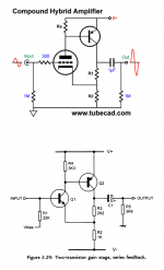
AMPLIFIER CIRCUIT

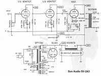
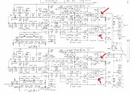
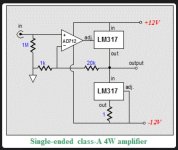
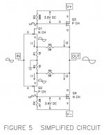
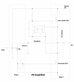
The Noir amplifier is a two transistor circuit, which is an idea that has been around quite a long time. Figure 1 top shows a hybrid tube+transistor amp circuit, and Figure 1 bottom shows an all-BJT version (from D.Self's book), to name but two examples. Noir takes this basic circuit and simply scales up the second stage bias current to 150 mA, then employs high wattage power resistors as the "collector loads." Simple.

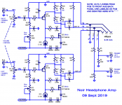
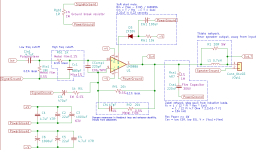
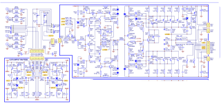
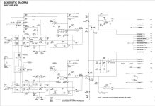
Fig 2 is the Noir schematic. Compared to Figure 1, the device polarities have been reversed. Now the input transistor is P-type and the output transistor is N. This is advantageous because N-channel MOSFETs have a gain-per-unit-silicon-area which is proportional to electron surface mobility. P-channels' gain is proportional to hole surface mobility, and is 2-3X less. All we need to do is flip the power supply upside down, and we get 2-3X higher gain per unit capacitance. An easy decision. Thus Noir uses a positive-ground, negative-supply arrangement, with the supply rail "NEGPWR" at about -22 volts. Just like germanium transistor radios in the late 1950s.

Transistor Q71 and "current regulating diode" D75 (a constant current source) form the input stage of the amp. They drive the gate of output transistor Q72, whose drain load is a 12 watt, 68 ohm resistor, implemented via a series-parallel arrangement of four 3W, 68R resistors. Each of these resistors dissipates less than 0.5 watts during operation, and even though they have a comfortable margin of safety (6X), they do get quite warm during operation. The midpoint tap of the resistors provides feedback from output stage to input stage. Thanks to equal resistor values on the top and bottom of the voltage divider, feedback is (1/2), thus gain is 2X (+6 dB). This choice of gain encourages the user to set the volume control potentiometer somewhere in the second half of its rotary travel, where channel-to-channel tracking is best.

Noir has a single ended power supply so it needs AC coupling at input and output; C72 and C76+77 provide these. As with other capacitor-coupled amps (notably the Pass ACA), Noir does produce an audible "thump" at turn on and turn off. If you find the thump objectionable, some elimination strategies include leaving the unit on at all times (as Pass suggests for the ACA), unplugging the headphones (or removing them) first, installing additional circuit boards/modifications inside the Noir chassis, et cetera.
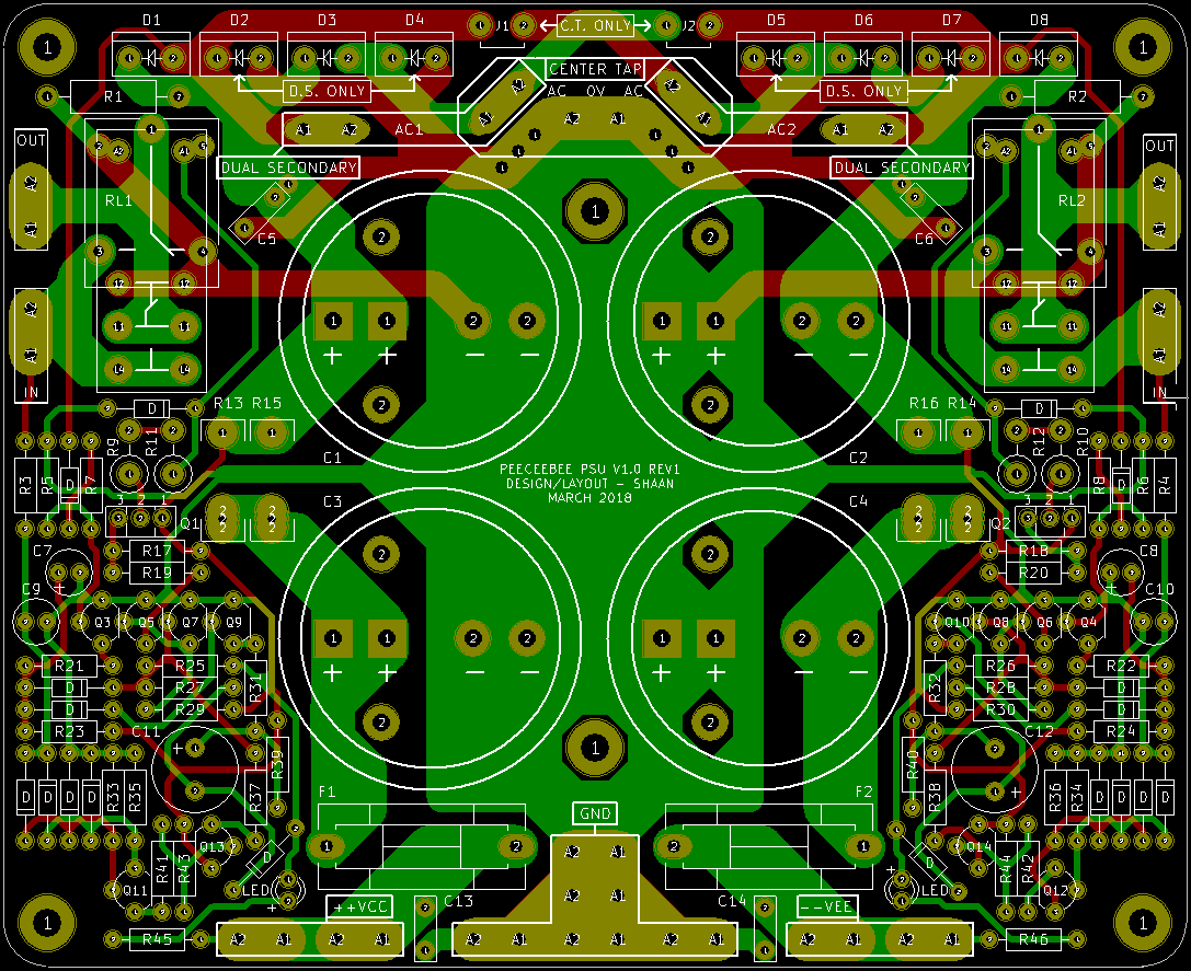
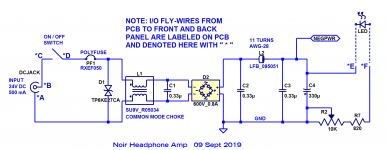
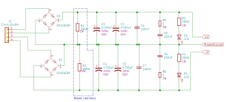
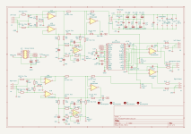
POWER SUPPLY

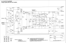
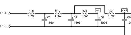
Fig 3 is the supply schematic. The DC wall wart output is filtered by a common mode choke and applied to a bridge rectifier. This means Noir can accept both (positive center, negative sleeve) wall warts and also (negative center, positive sleeve) wall warts. An LC output filter is then applied for additional smoothing. Potentiometer R2 and resistor R7 let builders adjust the current flowing through the LED "pilot light" and thus, its brightness.
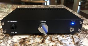
CHASSIS OPTIONS

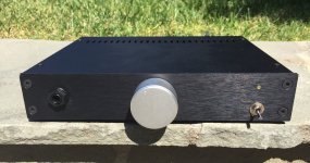
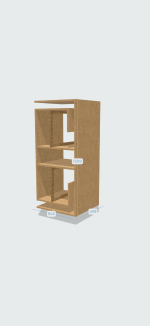
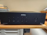
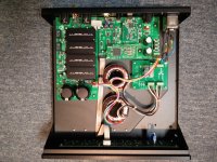
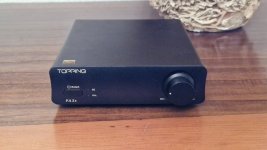
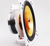
Fig 4 shows Noir in a "1U Galaxy" chassis from the diyAudio Store, with the silkscreened PCB front panel installed. Fig 5 shows the same unit, but this time using the brushed aluminum front panel that ships with the chassis. (I drilled it myself, using a drill press). I don't own the necessary tools to engrave lettering on the panel, but perhaps that's not necessary. There are only three objects and the function of each one is so obvious that perhaps no lettering is needed. Headphone Jack, Volume Control, Power Switch. Simple.

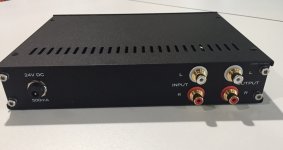
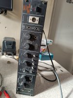
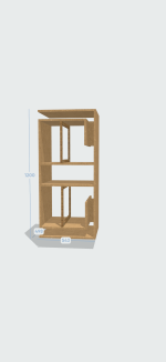
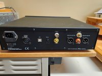
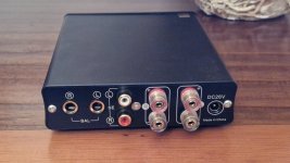
Fig 6 shows the rear of the unit using the PCB back panel. Here it definitely IS helpful to have lettering, to help you remember which RCA jacks are inputs and which are outputs.

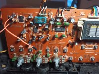
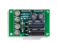
Fig 7 shows the stuffed and soldered PCB for Noir.

The final attachment is a Bill Of Materials in Excel Spreadsheet format for Mouser's BOM tool. The Noir sales page in the diyAudio Store has a link to a populated Mouser shopping cart, which might be more convenient when you're ready to order parts.

DIY BUILD COST

Now that the Store prices have been announced, we can estimate the cost of building a Noir at home: $70 for PCB + chassis, $85 for Mouser BOM (drops to $80 if you buy the ALPS Blue Velvet potentiometer at parts-express dot com instead of Mouser), $5 to $10 for fancy solid aluminum volume knob from eBay, $5 for misc nuts and bolts at your local hardware store. Total cost: approx $165. Of course you are free to purchase "Premium Parts" (exotic film capacitors, $100 potentiometers, silver wire, etc) if that's your pleasure.

HOW DOES NOIR SOUND?

Played into my Sennheiser HD 650s and also my A-T M50Xs, I would say that Noir is nuanced. Female vocals (Joan Diener, Marianne Faithfull, etc) were ethereal and otherworldly. And yet full orchestras sounded detailed and crisp, forceful with no detectable muddiness. "Mars" from Holst's "The Planets" suite was suitably terrifying. And ZZ Top kicked assz like only ZZ Top can do. Put on "Tres Hombres" , toss back a couple shots of Anejo , and daydream of Terlingua and Saragossa.

OLD DISCUSSION THREAD

Early prototypes of Noir were called by the code-name "T2". There was a forum thread for discussing T2, here, now closed, whose coverage of the early days might be of historical interest.

_

Attachments

  • Predecessor_Schematics.png
    Predecessor_Schematics.png
    99.4 KB · Views: 15,784
  • NOIR_Amp_schematic_09_Sept_2019.png
    NOIR_Amp_schematic_09_Sept_2019.png
    79.4 KB · Views: 15,655
  • NOIR_PSU_schematic_09_Sept_2019.png
    NOIR_PSU_schematic_09_Sept_2019.png
    41.9 KB · Views: 13,055
  • pinch_knob.JPG
    pinch_knob.JPG
    704.4 KB · Views: 11,595
  • Metal_Front_Panel.jpg
    Metal_Front_Panel.jpg
    299.7 KB · Views: 10,279
  • PCB_Back_Panel.jpg
    PCB_Back_Panel.jpg
    167.5 KB · Views: 4,994
  • Fully_soldered_PCB.jpg
    Fully_soldered_PCB.jpg
    331 KB · Views: 9,742
  • BOM_spreadsheet.zip
    BOM_spreadsheet.zip
    75.1 KB · Views: 1,467

Guitar effect loop switcher

So, I've decided to unearth a very old project of mine: an effects switcher for my guitar rig. Some 10yrs ago I wanted to do this with SSRs, but in the meantime I gave up on that idea and gravitated back to regular low-signal relays.

This will be a rack unit next to my effect pedals and will contain 10 effect loop modules, a power supply and an Arduino to control everything, from MIDI input. The modules themselves will be connected in series in groups of 4 or 5, so I can have some of them before the guitar amp and others in the amp's effects loop.

Now, I've finished a first version of the loop module and I'd appreciate some feedback on it. Relay NO is bypassing the pedal loop, while closed will feed the signal through the pedal.

PS: I know the diode setup across the coil is a bit overkill, but I'm not building this to cost, so it doesn't hurt to have the switch off time shorter, if only for bragging rights.

Attachments

  • Screenshot 2024-01-28 at 14.02.13.png
    Screenshot 2024-01-28 at 14.02.13.png
    54.8 KB · Views: 141

For Sale Electro-Print PSSS Push Pull Output Transformers

For Sale

A pair of unused custom Electro-Print Push Pull Output Transformers. Originally spec’ed for use in a DIY Poindexter’s PP 6V6 Musical Machine.

10K-P-P
UL Taps 44%
Tapped Output 8R
Partial Silver Stranded Secondaries
10W+@20Hz (no feedback)
- 1DB 17Hz - 31KHz at full power

6V6 tubes in photo shown for relative size. Not included in sale.

$600 total for the pair
-includes PayPal fee and shipping in CONUS.
International shipping charges to be arranged.

Attachments

  • IMG_5676.jpeg
    IMG_5676.jpeg
    883.2 KB · Views: 58
  • IMG_5678.jpeg
    IMG_5678.jpeg
    659.7 KB · Views: 54

F5 power amplifier

As many of you know, the F5 power amplifier design is done and is
merely awaiting delivery of the issue of AudioXpress which was
scheduled to be mailed April 10.

I feel that it's important to support AudioXpress, a magazine with
which I have a 35 year history, and which also serves as a
mainstay for the DIY comunity. Lately they have kindly printed
projects that I had already posted on the web, but I decided that
they deserve a little better than that.

Coincidentally, I had surgery of the 10th, and having apparently
survived, I am typing this from my bed.

Do not try to lift an XA200.5.

In any case, I know you're eager to get going and as soon as the
magazines arrive I hope that this thread will become a beehive of
activity. I have no doubt that members here will improve or at
least embellish the design.

Here's a copy of the simplified circuit.

Attachments

  • fig05 temp.jpg
    fig05 temp.jpg
    42.4 KB · Views: 78,480
  • Like
Reactions: Globulator

DIY speakers with active bass and passive mid/treble

Hi all, new to this forum. I was looking for some speaker advice on reddit and stumbled onto this forum. I have listened to some great setups lately, and a few of them had one thing in common. They had active bass, and passive mid/treble. Unfortunately they were all out of my budget, but it got me thinking, are there any affordable (under 3k or so) floor standing speakers that do the same active/passive thing. It made sense to me from engineering and economic point of view. That made me post in reddit. Apparently there are very few. I'm still browsing for my next speaker set and I could go bookshelves+active sub, but it wood look nicer if it was all in one enclosure. I was wondering are there any diy plans for a speaker with active bass, passive mid/treble, and if possible a horn design (not for the bass)?
I'm fairly competent in building things out of wood, metal, and doing electronics as well, but I just don't have the time to get into whole speaker cabinet design. That is a science in itself, and knowing myself, I would get obsessed and try to learn as much as possible before building. I also don't know what drivers are available on the market and where best to get them. So, I would need plans that include an active sub, preferably a horn, but could go with just a "regular" driver, and where to get all the necessary drivers/electronics. I live in Croatia, Europe, so anything I can buy within EU is preferable.
Tnx.

Trying to understand gating in tweeter measurements

I'm trying to figure out gating and tweeter measurements. Specifically in planar and ribbon tweeters. Dome tweeters do not seem to have the issue I am about to explain, or at least, not to the extent that ribbons and planar tweeters do.

Pertinent info: All the measurements you are about to take were taken at least 8 feet away from the nearest surface that could create a reflection.

Lets take a look a tweeter. This is the Hivi Planar RT1.3WE
https://www.parts-express.com/HiVi-...5dfNYjuxbfyS0oAO_Y0GaRLZ4JBgWhOhoCA10QAvD_BwE
1739150645005.png


Notice how it has the grill. Now, if we gate the measurement super close to the tweeter then we see the response as very smooth
1739150517340.png

Lets gate that further out now
1739150554103.png

Its already starting to get bumpy. This looks like reflective bumps, however, were this a woofer I wouldn't get any reflections until I gate out until there is reflective surface.
I will show you the woofer taken at this exact same time these measurement were taken.
Smooth even down to 230 hz
1739150746406.png

Alright, now lets gate that out to where there will be a reflection.
1739150781988.png

And there are our reflections.

I'll show another tweeter example. This is a ribbon tweeter>
GRS RT1.R
https://www.parts-express.com/GRS-RT1.R-8-Hi-Res-Neo-Ribbon-Tweeter-8-Ohm-272-202?quantity=1
1739150884206.png

This one also has a screen. It is set pretty far back into that cup so its possible its "horned" a bit. Anyways, lets take a look at its response gated really closely.
1739150951779.png

Pretty smooth down to 4khz.
Lets let it out a little bit more but still too far out to reflect off of a surface. This set of measurements were taken even further away from any reflective surface so there shouldn't be any until around 150 hz.
1739151042374.png

1 khz we have ripples. I saw this when I measured my friends studio monitors. In that case, it was from his desk. The desk was positioned around a foot away from the monitors. Once we found that out we moved the monitor and desk position so it was not a problem for his when he mixed his music. He is a musician.

I can only gate this out to 800 hz as that is as far down as I took the measurment. I will let it out far enough to get real reflections.
1739151226028.png

Now there are the reflections.


So my question is this:
Are these reflections of some kind or is it just completing the measurement as it goes or is this how measurement is aquired? As I always say, it is very possible I have a lack of knowledge here that needs filling in. I know enough to know I probably just don't fully understand.


If it is some sort of reflection then I wonder if I am trying to even out non existent response peaks when working on XOs when I should really just applying a boat load of smoothing to response.
1739151428036.png


I'm sure some of you are tiring of all my questions but I will just keep asking things I don't understand and cannot find answers for. I have a slogan that goes "the only dumb question is the one you failed to ask"

As always, thank you for reading this. Any and all responses will be read and appreciated.

Scryer ... or how F8 met Mighty SissySIT

To cite my favorite Audio Designer: "Audio design is perfectly mindless fun..."

:rofl:

Didn't intend to make this one; already made Babelfish F8, with few twists (just to justify Babelfish prefix), but that one destined to sit in folder

Some time ago, did found one interesting patent, sharing some basic virtues with Papa's F8, but nothing more interesting

As always, can't remember where tf I saved that pdf, couldn't find it, so few days ago tried to recollect my faint memory what was in .... and while I was thinking, had a napkin handy so I drew some sketches

Anyhow, everyone around (and his cat) is knowing basic principle of Papa's F8; few main virtues ( not both of these being in mentioned patent, feedback approach was in case) are single JFet in input stage, feedback loop containing JFet Rsource ( we know that already from F5 and few later ones) so that allowing that feedback loop is arranged as low impedance, so we can have majority of current feedback merits

now, F8 simplified

Consisted of two stages:
  • first one being common source P Jfet,
  • second one being (also) common source Semisouth enhanced mode Mosfet , without source degeneration; loaded with Mu Follower stage made of plain vanilla IRFP N Mos

OS Iq set in Mu stage ( optothingie), while input JFet drain resistor being trimpot - allowing setting of output DC Offset; as always - Papa's careful routine is selected Idss of input JFet, so he know what resulting drain resistance is, thus OLG, thus resulting THD SPectra of entire amp

Ha - go clone it, if you can :rofl:

///////////////////////////////////////////////////////

Edit on 16.08.2022. - final tests and schm values are in post #44, https://www.diyaudio.com/community/threads/scryer-or-how-f8-met-mighty-sissysit.388550/post-7098113

Attachments

  • F8 simplified.png
    F8 simplified.png
    469.9 KB · Views: 2,247

Those Magnificent Television Tubes

There are a lot of these tubes out there. I don´t mean the picture tube, but all the other ones. F. ex. the well known audio tubes 6CG7, 12BH7 and 6CW7 etc. are actually designated for TV-sets.

There are a lot of other quality tubes in Europe & US, costing almost nothing, like PL84, ECF82, PC86, PF86 ECF83, PL81 etc (P stands for 300mA heater current & E for 6,3V voltage)

F.ex. the EC/PC86 triode will outperform ther popular ECC88/6922 types with lower noise and higher gain & linearity.

In US there are 450 & 600mA heater current tubes I think.....(due to 115V mains & series connected heaters)

When a manufacturer sold a tv-set with 20-30 tubes and guarantee, the incorparated tubes have to be of very high quality.

If you have made an amp or other things with these tubes, please give a hint or schematic diagram in this thread.

Regards, Johan
  • Like
Reactions: veeblefetzer eddy

Getting more out of the miniDSP 8x8 kit

The miniDSP 8x8 is a great board and assumed to be targeting DIY’ers in kit form. However, as neat and easy to use the plugin may be, it does not allow to do much extra with the board other than crossovers or similar. What a waste!

I plan to use mine for a LXMini2 front speaker pair (three drivers) and a LXmini 2-way centre so the 8 outputs are perfect, only three inputs required. The plugin is ok for this but I also want to implement a few other features, such as tilt control, etc. Using the plugin’s four config’s is clunky at best, waiting for the dsp to be reloaded whilst listening to clicks is hardly user friendly!

My solution uses SigmaStudio to give me freedom of design and a Teensy 4 to setup the DSP and DAC instead of the on-board PIC microcontroller. As well as setting up the CODEC and DSP on startup, the Teensy can then provide remote control receive and control any DSP functions via the multipurpose I/O lines.


Some other uses could be to configure the analogue inputs in stereo pairs and switch between them for seamless source selection, something else the plugin does not allow for. I think 192KHz sampling rate should also be possible without having to restrict to just 2 analogue inputs with the 4x8 plugin.


Hardware modification of the board consists of adding just one resistor where there are already pads available, all other connections can be made via existing headers. Warranty of the board is assumed to be null and void once one starts to mess with it!

Project is still a work in progress but board analysis is complete and the basics are all now working. The concept is to keep the onboard PIC in permanent reset mode by pulling down the /MCLR pin via the PIC programming header on the board. This means the board has 100% backwards ability to stock mode of working. Via I2C, DSP reset and CODEC reset it is possible to program the board from the USBi SigmaStudio interface for development and then a Teensy for the final version, although the CODEC setup is only via the Teensy so a workaround is required when working with USBi.

Ok, sufficient for a first post, but if anyone has an interest in this project I’m happy to share details.

Woofer sing vs. cabinet talk

My current 3-way floor-standing loudspeakers got annoying “Umm” noise sonically. IOW, there’s excessive mid-bass in the lower vocal range, both male and female. At first, I thought it was caused by cabinet talk, so I simply lowered woofer’s crossover point. But the problem hadn’t gone. And, I found this issue in my car audio which has no speaker enclosures there at all. So I’m wondering whether the excessive mid-bass is generated by cabinet talk or woofer sing. Thus, how to indicate the origin of the noise, cabinet vs. woofer? Note that lowering woofer’s crossover point didn’t help.

Next, I tried experimenting tri-amplification by using active crossovers. I found that removing 85-170Hz region (with 12dB/octave slopes) by means of underlapping crossovers technique helped fixing the issue. In fact, the current setting crossover points on the original 3-way passive design are 550Hz high-pass for the 2-inch dome midrange (can’t go any lower) and 200Hz low-pass for the dual 10-inch woofers. I wonder since the problematic frequency range is around 85-170Hz, is it interesting to convert this project to 3.5-way system—by applying 200Hz low-pass to the upper woofer and 85Hz low-pass to the lower woofer instead of 200Hz low-pass to both woofers, and a little SPL tweaking on mid and tweeter?

No ground on SMPS

Hello,

I got this smps for my l12-2

https://a.aliexpress.com/_EuE444c

The thing is that it does not have any ground connection on the dc side so i grounded my amp boards and speaker output to the socket.

Everything is silent until I turn my dac on. When i do that, i get a hard buzzzz

When i connect my tablet instead of the dac everything is silent. In Guess have a ground loop with the dac.

My question is finally how can I ground the dc side? (Speaker negative and board ground)

Thanks

H2 V2 BUILD

Insofar as the H2 give-away sign up thread has become tediously long,
I am posting the build documentation here.

I am also happy to say that for those of you that missed the group
effort, it appears that the diyAudio store will soon offer these at a
nice cheap price.

:snail:

Attachments

Newbie question: amplifier performance improvement: how?

Hi, I have a basic newbie question.

A bit of background first. I have never designed an amplifier. I have read books on audio amplifier design by Randy Slone, Doug Self and Bob Cordell, and done some DIY circuit building, designed some PCBs from existing schematics.

Now for my question. 25, 30 years ago, Randy Slone and Doug Self used to design amplifiers whose THD went from, say, 0.004% at 1KHz to perhaps 0.05% at 20KHz. These were considered top of their lines. I'm focusing only on SS Class B here.

Now I am seeing discrete Class B amps routinely getting into triple-zero THD territory. The DIYaudio Wolverine. The Benchmark AHB2. The Topping B100/B200. And others. How are they able to do this?

I am aware of composite amplifiers which use a precision opamp in the feedback loop of a larger Class B amp. Neurochrome and Kaltecs.com do this. But both of these designers have done it only with chip amps. The Wolverine does not use an opamp in the feedback path. And I am told that it's damn hard to design a composite amp which does not oscillate, so I'm assuming that this approach is usable with a lot of effort with chip amps but unviable with a classic three-stage discrete design. I have heard the term TMC. What is it? I am aware of Miller compensation capacitors from Randy Slone's books, and he hesitated to use a CRC pi filter for stability concerns, he'd usually use just a single capacitor. Is the TMC I hear about fundamentally different from the stuff he explained? I am also aware that regulated supply rails for the input and VAS stages of an amp may deliver some improvements in performance, though I haven't seen it being used by Slone or Self, no idea why. Does this help?

So my question is basically: what are all the techniques modern designers are using to get to triple-zero territory? They are using parts which do not seem to be very exotic or unique, nor are their designs so narrow that we get a very unique set of circumstances which give us the magic. What changed in 20 years? Is this achieved by obsessing over details (like using an optical connection from front panel power switch to the rear, instead of an electrical cable, to keep mains hum out, or like feeding the supply rails of the actual amp with the output of a regulated massive power supply, like I'm told Halcro does), or by advances in topology and semiconductor parts quality?

(I am aware that my question is more an expression of my ignorance and misunderstanding than a simple search for some facts. I am hoping for some patient answers from some of you which will complete my education and clear my misunderstandings.)

My question is only about Class B SS amps.
  • Like
Reactions: Binjo

FFTs and Weighting Curves

So I have been using my Picoscope and taking FFTs to help troubleshoot my ground loop problems. It has helped tremendously in understanding the root causes. one thing I have been wondering though is should I be applying a weighting curve on my measurements. I realize it's not necessary to get meaningful results but I have noticed that when I get noise reduced way down it still measures 20 db higher than I see against commercial equipment and higher than it sounds. Should I be applying A weighting? Don'[t the commercial designs use A weighting to make things measure better? I haven't used Rewind but does it allow you to apply curves to FFT measurements? Notice that Audiotools on my phone lets you apply A or C to the FFT.

Hi guys, I'm Simon

Hi guys,
my name is Simon and I'm from Germany. I'm an electronics engineer for industrial sensors and want to do some audio electroncis as a hobby.
I'm a musician and play guitar in some formations.
I already have designed some circuits, and would like to get some comments and reviews for them before ordering the PCBs.
Also I'm looking forward to some gear-talk and analyzing and reviewing other peoples schematics.

Cheers!

NAD C272 vs S200

I was looking at the circuits for both these powerful amps and to my eye (I'm absolutely no technical expert) they look pretty similar, however to me, I think the far cheaper C272 is possibly superior (more complex?) *** I now have my doubts ...see #7 below.....Also, the C200 uses several op amps in the input buffer whereas the c272 uses a class A discrete design. The power supplies are pretty much the same using a large toroidal transformer and large capacity capacitors.

Attachments

  • NAD C272 AMP CCT.png
    NAD C272 AMP CCT.png
    333.4 KB · Views: 49
  • NAD s200 power amp.JPG
    NAD s200 power amp.JPG
    116.6 KB · Views: 48
  • NAD s200 Pre amp.JPG
    NAD s200 Pre amp.JPG
    103.6 KB · Views: 54
Projects by fanatics, for fanatics
Get answers and advice for everyone wanting to learn the art of audio.
Join the Community
507,673
Members
7,883,684
Messages

Filter

Forum Statistics

Threads
406,001
Messages
7,883,684
Members
507,673
Latest member
peedub