Application for DDRC-24?
I want to implement something akin to what Magnepan has suggested in the following:
Magnepan
See attached image from the Magnepan site will give you the idea.
I have 4 DML speaker panels to use in the following configuration:
The LG OLED TV only uses a single digital source (an Apple TV).
No subs & no surround needed in this application.
I don't want an AV receiver with lots of functionality I'll never use.
AV separates seem overkill.
The first of the attached images shows:
Can this work?
I think I could use the DDRC-24's DSP to make a "synthetic" center channel output that would work fine for my application. The DDRC-24's DSP probably has a number of ways to do this.
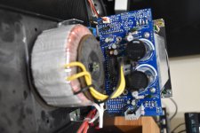
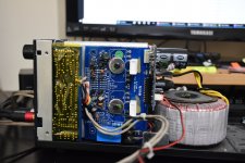
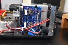
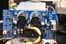
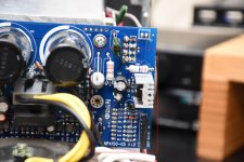
I would plan to use a DDRC-24 and a pair of ICEpower 50ASX2SE stereo amps (2X50W).
I've used similar amps with DMLs in the past. Great combination.
I don't need world class center channel. I just want to hear the dialog and believe that the DMLs will excel in such a configuration.
So, would this work?
Thoughts and guidance appreciated.
Magnepan
No place for a center channel speaker?
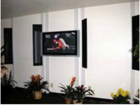
The photo below is of a demonstration in a hotel during a Consumer Electronic Show. The MC1s immediately flanking the on-wall video monitor provide a dual center channel array which can outperform a single center channel speaker.
A pair of our on-wall speakers achieves a center channel image in the same manner as a stereo system achieves a center image. By angling the speakers approximately 30 degrees to the wall, the center channel speaker on the left of the video monitor is on-axis with the viewer off to the right--- and consequently is louder than the center channel speaker on the right of the monitor (which is closer to the viewer). This "pulls" the audio image to the left and keeps the dialog centered on the screen better than point source speakers. It also raises the center channel image to the same height as the screen....
See attached image from the Magnepan site will give you the idea.
I have 4 DML speaker panels to use in the following configuration:
Left - Center left - TV - Center right - Right
The LG OLED TV only uses a single digital source (an Apple TV).
No subs & no surround needed in this application.
I don't want an AV receiver with lots of functionality I'll never use.
AV separates seem overkill.
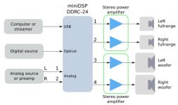
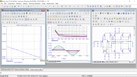
The first of the attached images shows:
1. An image from the DDRC-24 User Manual showing how it can support left right and 2 sub woofers.
2. My markup of the above wondering if a DDRC-24 could support what I'd like to do.
2. My markup of the above wondering if a DDRC-24 could support what I'd like to do.
Can this work?
I think I could use the DDRC-24's DSP to make a "synthetic" center channel output that would work fine for my application. The DDRC-24's DSP probably has a number of ways to do this.
I would plan to use a DDRC-24 and a pair of ICEpower 50ASX2SE stereo amps (2X50W).
I've used similar amps with DMLs in the past. Great combination.
I don't need world class center channel. I just want to hear the dialog and believe that the DMLs will excel in such a configuration.
So, would this work?
Thoughts and guidance appreciated.


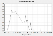
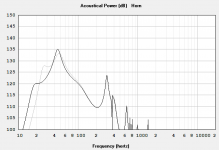

 (or is measuring and calculating way more complex than expected?