Clearance around a Behringer DCX?

I'm getting ready to put my system back into action.
I don't have a rack mount and need to knock something up quickly.
Unit is going into a cheap IKEA TV cabinet with only passive ventilation.
I've read the manual several times and if there is information about minimal clearances I have missed it.
Can the members here give me a quick guideline to a good minimum clearance around these units please.
Space is tight or I'd simply allow 1RU top and bottom
Thanx in advance

DSP with Asian ADAU1452 DSP Board+AD1938

Hi guys…

The site is great, and most of it is over my head. But thank you.

I am coming here with my hands help up. Help. I have searches all over. I am a total novice and most things I read have trouble understanding.

The Asian boards do not come well documented, and I have no idea what is in and what is out unless it is obvious. All the boards seem different, and this confuses me.

I have wanted to do DSP and Speaker Cross-over for many years and it is all very complex. I only want to do 2-Way Cross over and Sub. I would really love a digital in and digital our so I can use my own DAC’s.

But I think, please do not shoot me, I think this is an OK combination…ADAU1452 DSP Board+AD1938 Audio CODEC Board+USBi Emulator Burner USB Programmer | eBay

But the seller and other sellers, have no information. I really do know what all the outputs are or how to hook it up or if and where to put power.

Also, I cannot find instructions on how to use these boards with Sigma software to do all the DSP.

I have been looking for over 2 years and I am still confused.

Has anyone used this board and willing to show me??? I am no technical bloke.

Billy Bags Amp Stands,12x12, Matched Pair, Designed for Aleph 2s or Aleph 5

Pair of Billy Bags amp stands. Asking $200 for the pair.


These were designed for the Pass Aleph 2s or Aleph 5, which they fit perfectly, but of course they can be used with other amps. The usable size on the top is 12x12, with the rails adding an inch or so on each side.

I'm willing to sell just one, if you have an Aleph 5, but I'd much prefer to sell them together.

I do not have boxes for these (obviously, really, right?) so would prefer something local. But I can certainly cobble something together for shipping. I'd recommend a little plywood crate, as they are heavy and will not play well with cardboard, I don't think. (I can do that easily enough. I've got lots of plywood lying around.) That's why I've set the shipping weight to 20lbs. But shipping cost will be whatever the actual cost is, to be worked out between me and the seller.

PC Hum/HDD noise into preamplifier

I am looking for help to solve a small amount of noise, consistant with HDD operation, mouse movements, etc... Heard at the speaker and enough to be annoying.
Set up is an Elekit Amp and Elekit Pre-amp, turntable and PC, with RCA out> into the Pre-amp. When listening to vinyl there is absolutey no noise, it's perfect. If I decide to listen from the PC (J-river/Flac), i.e. use a different input at the pre-amp, there is annoying humm as above. I have a power board that filters and everything is plugged into the same board from 1 AC outlet. I have tried a few of the ferrite chokes on the power cords to no avail. Pulled the PC apart and looking at the sound card, chassis, etc... I can see little screws that appear to earth everything as it should. Looked around on the forum and wouldn't know where to add a wire to stop a ground loop, if that is the issue, from occurring.
It is a recently built PC with a EV brand sound card.
My question possibly is, if the noise can't be solved, is it easier to purchase something that will use SPIF/Toslink (PC has this) in and RCA out (to the pre-amp), that doesn't reduce the sound quality, and get around the noise issue that way, or is there more I can do to solve to problem at it's source, i.e. in the PC.
I can add images of the PC internals, etc.. if that helps.
All help appreciated as I'm fairly new to the audio world.

James

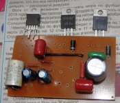
TDA2030 with transistors

Hi there!
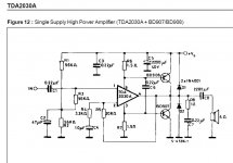
I decided to try scematic TDA2030 as a tranzistor driver. And i have some questions about that schematic.
Did anyone do such a scheme? Does it sound normal? Will that schematic give me some troubles with installation and tuning?
Starting at what output power will additional transistors begin working?
What power supply unit should I use? How many watts?
And in this scheme, the gain factor is 10 as I understand it. Is this enough for an input signal level of 500 mV? What values of pR4 and R5 should I use?
I will definitely try this scheme. I already made a circuit board and almost soldered all the components.

Attachments

  • P3310064.JPG
    P3310064.JPG
    732.6 KB · Views: 1,590
  • P3310068.JPG
    P3310068.JPG
    916.3 KB · Views: 1,387
  • P3310066.jpg
    P3310066.jpg
    216.7 KB · Views: 1,395
  • Снимок.JPG
    Снимок.JPG
    73.3 KB · Views: 1,560

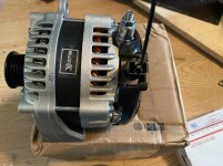
High Output Alternator

I’m finishing up my stereo system in my truck .

The last thing I need to do is install the high output alternator and battery bank .


I will be running this alternator separate so it only charges the back battery and will have nothing to do with the stock charging system this is a stand alone alt .

I tried contacting the manufacturer but never heard back .

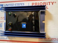
This alternator has a external regulator.

Here are some pics but it’s been awhile since I hooked up systems .

My question is

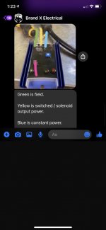
1 terminal of the regulator goes to constant power
Another Terminal goes to ground

Then there is a terminal that goes to the field
And last terminal goes to switched power/solenoid output power .

The plug on the alternator has only 1 wire coming out .

So the question is what is the field wire ?
And what is the switched power/solenoid output ?

Wondering how I hook this up ?

I need to know what to hook the wire coming out of alt goes to
What the field wire goes to ?
And the switched power/ solenoid output goes to ?

Any info would greatly be appreciated

Attachments

  • B5E3E603-0197-46C7-B9BD-3B13B52D580D.jpg
    B5E3E603-0197-46C7-B9BD-3B13B52D580D.jpg
    993 KB · Views: 137
  • B08429B7-2C83-41B1-A9C2-0823B0066924.jpg
    B08429B7-2C83-41B1-A9C2-0823B0066924.jpg
    918.2 KB · Views: 139
  • 1ED21E8B-10B0-4931-A6BE-F8A1AD9496C6.jpg
    1ED21E8B-10B0-4931-A6BE-F8A1AD9496C6.jpg
    74 KB · Views: 140

Signal Ground Question

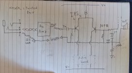
I've been preparing for my next build, and wanted to get the whole signal grounding thing right. I have Doug Self's book, and I have been referring to Fig 25.1 on page 600 (6th ed). I'm not sure if I'm allowed to post that here, but it is a helpful diagram.

I wanted to draw it out and see if it made sense to me, and hear if anyone has any suggestions.

My main takeaways are:


1. Local rail decoupling capacitors need to have ground at star point
2. Speaker return have ground at star point
3. NFB ground should be with signal ground


My main points of confusion:


1. In preamp, do I add an additional return path for signal ground to PSU ground on its PCB? Or, do I only allow preamp signal ground to be returned through the main amp unit and its star point? In the picture, there is no connection to signal ground to PSU ground that comes in with supply rails.
2. Is the 100 ohm resistor that separates signal ground and PSU ground at the star point necessary?


"drawing" 😱 is attached, appreciate any feedback/discussion. Thank you!

Attachments

  • PXL_20210722_204325312.jpg
    PXL_20210722_204325312.jpg
    638 KB · Views: 685

[Europe] FS/FT Various parts / NOS DAC MOSFET XO PSU...

Attachments

  • Alim_LAB_DSL_POTS.jpg
    Alim_LAB_DSL_POTS.jpg
    392.1 KB · Views: 234
  • CXO-48MHZ.jpg
    CXO-48MHZ.jpg
    179.9 KB · Views: 253
  • LEMO.jpg
    LEMO.jpg
    628.9 KB · Views: 239
  • LUMBERG.jpg
    LUMBERG.jpg
    443 KB · Views: 233
  • TAMURA_6.3x1.25VA.jpg
    TAMURA_6.3x1.25VA.jpg
    278.6 KB · Views: 242
  • P6NB80_Power_MOSFET.jpg
    P6NB80_Power_MOSFET.jpg
    178.1 KB · Views: 152
  • B7NK80_Power_MOSFET.jpg
    B7NK80_Power_MOSFET.jpg
    222.5 KB · Views: 140
  • LM2596_DC-DC.jpg
    LM2596_DC-DC.jpg
    252.4 KB · Views: 135
  • BB_DAC7644.jpg
    BB_DAC7644.jpg
    158.9 KB · Views: 134

another JL 500/1 - no power, no output

This amp was previously working, today it seems to have quit.

Be aware I've been using this amp with faulty supply wiring. Fused distribution block had a loose internal connection. This was discovered and repaired as of today.


JL 500/1, main board revision 10


Tested 10-pin connector.


Supply voltage: regulated 14.2v from bench power.
Pin 1: 0.0
Pin 2: 0.0
Pin 3: 0.54 v
Pin 4: 5.65v
Pin 5: 145 mV
Pin 6: 14.15 V
Pin 7: 0.0
Pin 8: 40.2 mV
Pin 9: 192.3 mV
Pin 10: 0.0


PCB looks pristine. No burnt soot, no bulging caps, no hot spots that I can identify.


Other than double checking power leads, I'm unsure how to proceed. Any guidance is appreciated.

Application of golomb rulers to sparse line arrays

Inspired by this...

"Dipol 08" Baffle Dimension and List of Crossover Parts

I decided to do my own open baffle golomb line array.

A lot of testing with previous prototypes showed that I want a narrow but long/high open baffle line array without any power or frequency tapering.
I decided to try eight units per side.

Perhaps the following will help somebody struggling with the application of the golomb ruler to such a so called sparse line array.

I found some statements that it is impossible to apply the ruler to a bigger number of speakers assuming that the base unit of the ruler needs to be the speakers vertical dimension.
So a 8 speaker golomb line array made of 10cm speakers will have a total height of 340cm because an order 8 golomb rulers length is 34.

Golomb ruler - Wikipedia

But this is a too narrow interpretation of the Golomb ruler.
Golomb rulers help to get an optimal distribution of units over a given length e.g. where you do not have enough units to cover the entire length (sparse line array).
"Optimal" means that the DISTANCE between ANY two units in the array is UNIQUE.
It is all about the distances not the values or the ruler

distributed.net: Project OGR

The 8 unit golomb rulers values are
0 1 4 9 15 22 32 34
which is written as distances
1 - 3 - 5 - 6 - 7 - 10 - 2 (= 34)

The room height is 250 cm
I wanted a line array that is at least 70% of the height and decided to make the array 180 cm high.
The speakers vertical dimension is 12cm x 8 speakers = 96cm covered by the speakers.
So there are 84cm left of my baffle
Divided spare room by the ruler length of 34 = 2.5cm
This "base unit" is multiplied with the golomb distances between the units,
e.g. from 0 to 1 = 1 * 2.5, from 1 to 4 = 3 * 2.5, etc.

Finally added arbitrarily 4 cm on top and bottom of the baffle just to have something to fix the thing somewhere.
The center of the array is at listening height.

754818d1557158340-ultimate-baffle-gallery-dipolv4_all-jpg


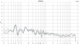
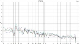
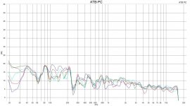
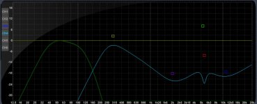
I attached the DSP settings and measurements at different distances and heigths
They show that the speakers melt nicely together at about 350cm distance which is my listening position.

Attachments

  • line_array_dist_150cm_diff_heights.JPG
    line_array_dist_150cm_diff_heights.JPG
    104.8 KB · Views: 461
  • line_array_dist_250cm_diff_heights.JPG
    line_array_dist_250cm_diff_heights.JPG
    107 KB · Views: 446
  • line_array_dist_350cm_diff_heights.JPG
    line_array_dist_350cm_diff_heights.JPG
    106.3 KB · Views: 448
  • reckhorn_curves.JPG
    reckhorn_curves.JPG
    101.6 KB · Views: 459
  • Like
Reactions: Naturlyd

volume control relè

Hi everyone.
I'm trying to design and build a simple relay volume control. I would like to do it with the requirements that I am going to list below:
- simplicity
- pure electronics, no PIC, microcontroller, firmware and software.
- easy to repair in case of failure
- single entrance
- remotely controlled with Ir or RF remote control
- no display in my opinion is not needed.
- no SMD but integrated with base so you can replace them without unsoldering.
- silent
- each relay of the signal group must have two separate contacts to obtain two channels
- functions: increase / decrease, mute / restore, storage of the volume prior to switching off.

I have already prepared the heart of the circuit but I ask you for some advice on choosing the components.
- which relays to use for the signal to obtain silence and long life?
- which single coil bistable relays to use to obtain silence and
lasting in time?
- which resistances to use?
- which configuration do you recommend to use for the resistance chain
? series? shunt? ladder?
- how to neutralize the micro-bounces of the relay contacts?
- which system to use to avoid overlapping two volumes
when do you change? I thought of inserting a small delay circuit when the relay is switched on. what would you do?

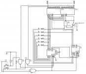
I briefly describe the circuit I have attached.
the two counters in cascade CD40193 have 2 inputs to increase or decrease, they control two 74HC154 and the outputs of the latter go to control the relays dedicated to the signal.
by enabling or disabling the two inputs E2 of the 74HC154 the mute / reset function is obtained.
the NAND U1 gate has the function of updating the outputs with the inputs of the CD40193 at power on, through the LOAD input.
the six bistable relays have the function of memorizing the volume prior to switching off.
of course the circuit is not complete, the remote control circuit is missing, the one that controls the bistable relays, the delay circuit of the signal relays.
Invia commenti
Cronologia
Salvate
Community

Attachments

  • controllo volume.jpg
    controllo volume.jpg
    137.4 KB · Views: 775

multiple soundcards as active processor for HT?

I'm planning to build a 5.1 surround system for my home theater (see thread http://www.diyaudio.com/forums/everything-else/282286-diy-home-theatre-where-start.html) with all active crossover and individual amplification. 3 way frontstage and 2-way rear surround

A friend of mine built a carputer about 10yrs ago where he would use the different output of a surround sound car to drive active 3-way frontstage. Would it be possible to do the same thing with an home theater? If it has been done, what kind of equipment would be adequate?

smd soldering in the EU

Hey there diyaudio community,


my fine motor skills lately just aren't what they used to be. However, I have some unpopulated PCB's and all needed parts laying around for quite some time now and would really like to at least have the DAC finished, but it would take me forever with my shaky hands right now. They are good enough for soldering point-to-point or trough-hole, but just not for those teeny-tiny smd parts.


Does anyone have experience with a PCB assembly ~smd-soldering~ service in the EU?
Or better, would maybe a member on here be so kind and do the smd soldering job? Against payment of course or maybe a payment plus NOS tubes, chokes, transformers or other parts I intend to sell somewhen anyhow.


Any help is greatly appreciated and I hope this is the right sector -otherwise please move it to the correct one.


Thanks,
Brzzl

DOD 834 Series II active crossover

Hi folks

I'm having no end of trouble trying to get my new active crossover setup working.

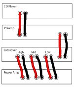
I have a NAD 1000 Preamp feeding into a DOD 834 Series II active crossover which splits the signal into Hi, Med and Low, which I am then feeding to a Sonance Sonamp 1230 power amp working in bridge mode to give 6 channels.

The problem is that when connected as below, with cables I made that have a mono 6.35mm jack on one end and a male phono on the other, I am only getting sound through one channel.

I've verified with a multimeter that all the cables are working properly.

If I press the stereo-mono switch on the front of the DOD 834, it changes the behaviour, it appears that now, the highs are on one channel and the lows on another.

I'm most confused, I can't for the life of me figure out what is wrong.

Attachments

  • Bridged 4.png
    Bridged 4.png
    69.3 KB · Views: 226

HT room with a large openning

Hey guys...

We have a HT room in a duplex house.
Room size is 20X14X11ft.

The room is not completely closed, because there is a large opening (6ft x 11ft) for the stair case that connects ground floor and first floor.

How necessary is it to close this openning for pressurizing the room with tactile movie bass?? (Basically install a big door)

Is it possible to pressurize the room that has a big openning ??

Quadratic/Skyline diffuser questions.

A friend of mine has been asking me about building him either some quadratic or skyline diffusers. He lined every wall in his listening space with acoustic panels and he's now decided he doesn't like how dull it sounds.

I purchased a book detailing the BBC designs of diffusers and figured that would be a good place to start. He's asking about making some pretty large panels to hang from his 10' ceilings, 4x8' size panels.

My question for anyone whom might know is. Are the size of these types of diffusers scalable?

For example if a quadratic diffuser calls for a 4x4" square well, can that be expanded to a 6x6" square well?

Or in the case of a skyline style diffuser where plans call for 2x2" blocks at different heights. Can that be scaled to say a 4x4" block and still use the same heights outlined in the plans for 2x2" blocks?

Most of these designs make a roughly 2x2' panel, if I were to expand this to 4x4' instead of essentially making 4, 2x2' panels can these designs be scaled to accommodate a larger size panel?

Protection Circuit - Crowbar - Zener vs SBS

Hi

I have bee looking at crowbar circuits and came across this thread. In it is decribed the dc protection circuit used on the quad 405. It uses a Silicon Bilateral Switch to activate a triac which then shorts the amp out. It also contain a filter network to ensure the thing doesn't trigger all the time.

My question here is simple. What advantage in this instance does the SBS hold over a zener? The only thing that I can see is that it may be a bit more accurate with the "trigger voltage", but surely this voltage does not realy matter.

The reason I ask is that these SBS's are horrendously expensive but at the same time I am convinced that quad must have made this decision for a reason.

The Intellectual People Podcast - JDS Labs

John Seaber set out on a mission. He wanted a well performing headphone amp. Little did he know that his search would form a very successful business manufacturing an enhanced version of Chu Moy's cMoy design. Selling tens of thousands of these units, yes, you read that right; ultimately led to his own design. His story is quite neat to listen to. Enjoy!

How did NwAvGuy help JDS Labs? | John from JDS Labs | Ep 37 - YouTube

Attachments

  • JDS Labs Thumbnail.jpg
    JDS Labs Thumbnail.jpg
    86.3 KB · Views: 106

FS: Several drivers. Another clearance

Time for another clearance:

2x SBAcoustics SB17MFC35-8 midwoofers. NOW SOLD.


2x SBAcoustics SB26STCN-C000-4 tweeters. NOW SOLD.


2x HIVI TM1A tweeter + midrange. In their original box. Never used. Bought 4 months ago and opened just for pictures.
Asking 60€ for the pair.


2x HIFIDIY AL-100 AMT tweeters. In their original box. Never used. Bought 4 months ago and opened just for pictures.
Asking 20€ for the pair.


2x Audaphon MB18-8 midwoofers. Used but in very good condition. An incredible well built unit.
Retail 50€ each. Asking 50€ for the pair.


2x SEAS 27TDFC H1189-06 Tweeters.
SOLD.

Paypal fees and shipping not included.
For several units price will be dropped.
Questions, please, PM me.

Pair of top of the line carbon fiber woofers with 4 inch magnet

These are a pair of woofers from emerald physics top of the line open baffle

carbon fiber
huge spider
largest magent

made by eminence

pictures: Emerald physics 4.4 - Album on Imgur

this ad is for just the pair of woofers

i;m giving the woofers away for free but whether i have to do two boxes or one box you have to pay for all packing and shipping cost via UPS

6SN7 > 6SN7 > 300B , 6SN7 DC 300B

Hi DIYers,

I am working on an unique directed coupled 300B amp.

All triodes are common cathode configuration.

2 stage 6SN7 amplification, first stage 6SN7 and second stage are capacitance coupled, second stage 6SN7 and 300B are direct coupled.

I don't use high watt resistance to raise cathode voltage of 300B, instead I use negative voltage supply for second stage 6SN7.

I use 866A tube in B+ and EY84 in B-

All parts and chassis are ready for assembly.

Happy to hear your comments!

Coral Beta rubbing voice coil / cloth surrounds

When further listening to my newly arrived and otherwise good sounding Coral Beta 10Bs, I noticed a buzzing sound on certain bass notes (mainly lower cello and middle electric bass). When I unplugged the buzzing driver and gently pushed the cone inwards, I heard a rubbing sound. Very scary. Only if I pushed it to one side however. I suspect that either the voice coil is damaged, or I need to re-align it. Maybe both. Anyhow, I need to somehow remove/release the cloth surrounds and spider. Anyone done this before? What type of glue can I use to stick the surround to the frame again, if I manage to salvage it? Also, is there a place where I can buy new white cloth surrounds for a 10" speaker?

JL Audio ProWedge CS212OG-W6v3 vs JL Audio CLS110RG-W7AE

Hi, 1st post! Got a burning question which has been asked to death. As per title, can't decide on the above. Please help. & it has to be these 2 only strictly from JL Audio.

-1st option is 2 x 12W6v3 subs in a dual opposed sealed JL enclosure powered by an HD 1200/1 amp - JL Audio ProWedge CS212OG-W6v3

-2nd option is a 10W7 sub in a sealed JL enclosure powered by an HD 750/1 amp - JL Audio CLS110RG-W7AE

The car is a Mercedes Benz CLS63 Shooting Brake :car:

Sound Quality is my main priority and saving boot space. I've heard that the 12W6v3-4 sounds better than the 10W7 but others say they all sound good.

I rarely listen at reference loudness - mid volume mostly. I still want to be thumped in the chest or massaged by bass though when in the mood!!

The 10w7 would occupy slightly less space & also cost a bit less. I suspect the 2 X 12W6v3 may have more control and composure as its rated at 1200 watts vs 750watts for the 10W7.

Obviously the 1st option has more cone area and will be working less comparatively. But the 10W7 has 23mm x-max vs 19mm for the 12W6v3

I appreciate that custom enclosures may yield better results as they're bigger than JL Audio's apparently conservative sizes. But it has to be from the above JL's enclosures as I will be changing cars next year. Decisions, decisions, decisions... Thank you in advance 🙂

10W7AE-3

Free Air Resonance (Fs) 30.6 Hz
Electrical “Q” (Qes) 0.578
Mechanical “Q” (Qms) 7.647
Total Speaker “Q” (Qts) 0.537
Equivalent Compliance (Vas) 1.28 cu ft / 36.1 L
One-Way Linear Excursion (Xmax)* 0.9 in / 23 mm
Reference Efficiency (no) 0.17%
Efficiency (1 W / 1 m)** 84.3 dB SPL
Effective Piston Area (Sd) 59.8 sq in / 0.0386 sq m
DC Resistance (Re) 2.75 Ω

12W6v3-4
Free Air Resonance (Fs) 26.919 Hz
Electrical “Q” (Qes) 0.487
Mechanical “Q” (Qms) 9.365
Total Speaker “Q” (Qts) 0.463
Equivalent Compliance (Vas) 1.920 cu ft / 54.37 L
One-Way Linear Excursion (Xmax)* 0.75 in / 19 mm
Reference Efficiency (no) 0.11%
Efficiency (1 W / 1 m)** 85.4 dB SPL
Effective Piston Area (Sd) 75.338 sq in / 0.0486 sq m
DC Resistance (Re)*** 6.493 Ω
DIY Subwoofer Design help

Hi there,

I have an 18" Mackie branded (but built by Eminence) driver laying around that I got off a friend a while ago. I would like to build a box for it to put it to use, and so I put the T/S parameters into WinISD. It defaulted to an absolutely massive 17.3 cubic foot box, which does not seem correct - or is it?

The parameters are as follows:

Re 3.20 Ohms fs 38.3 Hz
Le 0.72 mH Mms 145.5 grams
QM 8.03 Mmd 122.0 grams
QE 0.51 Cms 0.119 mm/N
QT 0.48 Rms 4.354 N*sec/m
Xmax 6.67 mm Vas 238.4 liters
Pmax 450 Watts SD 1188.0 cm^2
Bl 14.85 Tm VD 792.1 cm^3
Coil Diameter 4.00 Inches EBP 75.3
Gap Height 0.375 Inches Magnet Weight 109 ounces
Efficiency 2.54 % Winding Width 0.900 inches
SPL 96.1 dB 1W-1m

Could someone please tell me if i'm doing something wrong? Or would you recommend to just get a new driver.

Thanks,
Joe

HELP - TC-510-2 Reel to Reel playback

Hi all,

I'm hoping there are some generic aspects to this issue that someone can help me out with.
FFW and RW switches are working on my Sony TC-510-2 however when I engage Playback, nothing happens.
I've been looking at the unit, the schematic and the layout and trying to piece together what is going on.

The PLAYBACK know is attached to two switches as below.
S15 leads to the Servo Amp board and S16 is for timing:

The Layout diagram looks like this:
Wire <28> is 14V from the power supply. When PLAYBACK is engaged the little button on the left of the switch is released.
Now the trouble is, when I probe all three pins, whether PLAYBACK is engaged or STOP (i.e. either position of the switch) ALL 3 pins on that switch read 14V (though when I probe resistance there is about 100 ohms or so)

Following the important wire <67> leads to the Servo Amp Board and I've highlighted exactly where that wire goes. Now my understanding of circuits gets hazy here. There's a transistor, but according to what I probed at the mechanical switch, that highlighted yellow wire is always at 14V. So the switch appears to not have any effect. Where I get confused is two things:

I can't tell firstly what the effect of switching between PLAYBACK and STOP should be from the diagrams above? Should wire <67> be 0V at STOP and 14V at PLAYBACK, or is it the other way around?

Secondly, if PLAYBACK should be 14V, and somehow the mechanical switch is faulty and leaving it "on" all the time, why is the servo motor not running?

Thank you for your help!

What thread to use for wire harnesses?

Hi friends

I just got impressed by both the documentation of the (Aussie) Advisory Circular AC AIRCRAFT WIRING AND BONDING ...
and the bespoke audio passive preamp...

and thought that I should/could do that too. 😀:wrench:

What thread/string can be used to get there? It seems like it's a bit a specialty material, can it be substituted?

Yes of course I could just try'n err, but probably there's somebody more experienced willing to share a bit of knowledge?

Thanks
david

Loudness pcb with 50kOhm design, could I use it with 10k log pot?

I found (and ordered) a loudness PCB on which the capacitors (4 pieces of 2nF and 4 pieces of 0 .033 uF) and resistors were "calculated" for a 50k Ohm volume potentiometer.

I am currently using a very good sounding 10K TKD 2CP-2511 log pot in my passive preamplifier.
There is also an Audio Note 100k log pot "in reserve".


My questions are: what happens if I connect the 10k Ohm or the 100k Ohm volume potentiometer to a pcb "designed" for a 50k Ohm pot, without replacing resistors or capacitors?


Or, as far as I know, for a 10k Ohm pot I would have to change the resistors to 1/5 value and the capacitors value to 5x. If this analogy is correct, when I am using a 100k pot do I have to change the resistors value twice of original and the capacitors value to the half?

Choked Thread

PSU for TPA3255 : https://www.diyaudio.com/forums/power-supplies/376297-psu-tpa3255.html#post6766724

The forum boilerplate bottom-matter does not render. Nor a Reply box. There is a base64 clog.
(Me: Win7, FireFox 91.0.2)

Digging in, below .."the range is from 18V to 53.5V D.C." there is a humongous Base64 URL at line 738:
"....forums/data:image/png;base64,iVBORw0KGgoAAAAN........"
98,733 characters

And again, below "these are quite cheap when bought on AliExpess for examle:" at line 760:
".....forums/data:image/png;base64,iVBORw0KGgoAAAAN......."
1,135,725 characters

The second one seems to be the choke-point. But neither renders even when opened in another tab/window.

Mark Levinson 332 differential bias

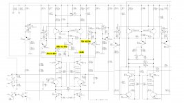
I bought a ML332 recently. During the recap, I noticed that the left side voltage gain board is much warmer then the right side's. ​I probed around and found that the bias of the left voltage gain board seems off, quite off. The picture attached explains. The +/-supply is +/-114v. The differences between the left board and right board are
1. Q12 collector, -45v vs -15v
2. U6 collector, 72v vs 55v.

The bias is very different. Because #2, the bias to the second stage through R110 & 110 are also off. Anyone has experience on that and what might be wrong? I am thinking to replace SSM2220 and 2N6730. They both are obsoleted, Mouser don't carry and I see some people are selling them on Ebay but with 2 weeks shipping time. Other than Ebay, any recommendation on where to buy obsoleted components.


Thanks,
cfy30

Attachments

  • ml_332_bias.jpg
    ml_332_bias.jpg
    665.1 KB · Views: 429

Stanton quad channel headphone help!

Hello--

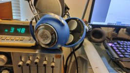
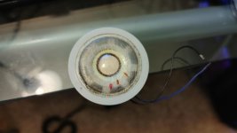
I recently acquired a pair of Stanton Sixty-Five four channel headphones. For whatever reason, all 4 speakers are blown out in them... I am in search of replacement drivers, and have it narrowed down to two different ones (i think). I am just looking for opinions on them, or possibly another suggestion of speaker choice. Original driver diameter is 40mmx17mm(?) (dont remember depth, but there is spare room behind the speakers). I initially tried getting help from members in the diy section of head-fi.org, but apparently no one knows nothing about speakers on a forum about headphones 😕

I havent decided how to wire them up yet either. There is a switch in one of the cables to go between stereo and quad (has two quarter inch plugs for quad usage), though I am not sure if stereo parallels the speakers or just disables two of them.

Also, would it be worth plugging the air ports on these, or possibly adding sound material behind the speakers? On my Sixty's, I ended up replacing the blown 2 way dynamic speakers with 2 way car speakers, and plugged the airports based off a really old forum post that said doing so really helps with lower frequencies. I don't have an unmodified set of sixty's to compare against, so I'm not sure if plugging the air ports helped or not...

#1: http://www.newbdnc.com/wp-content/uploads/datasheets/BFC-D45-7-32-012.pdf
I like these cause they have the lowest Fr, and have the most data available about them Frequency response seems decent as well. If they were paralleled, that should bring the resistance down to a reasonable 16 ohm.

#2. Access Denied
Similar to #1, though the frequency chart is blank :/

I know nothing when it comes to speaker choice, so any and all input on the matter would be greatly appreciated! 🙂

Attachments

  • 20210809_154739_HDR.jpg
    20210809_154739_HDR.jpg
    993 KB · Views: 191
  • 20210809_154748_HDR.jpg
    20210809_154748_HDR.jpg
    806.7 KB · Views: 186
  • 20210809_154806_HDR.jpg
    20210809_154806_HDR.jpg
    868.9 KB · Views: 184

Dual Secondary Toroidal - Balanced Operation For DAC Supply

Hello,

Just wanted to double check my thinking is sound for a power supply I am working on.

I am building a PCM56 DAC, my first digital design, a simple NOS implementation. I came across the idea of using a balanced isolation transformer prior to the mains transformers to reduce mains-coupled common-mode noise.

I had looked into a custom toroidal for this purpose, but had not found a transformer maker for the job.

Instead, I am looking at an off-the-shelf option. Maximum secondary current draw for my design at 120VAC is ~70mA. I am looking to use this transformer from Triad Magnetics, VPM240-100. It is a dual primary (120VAC, 240VAC) dual secondary (120VAC, 240VAC) medical grade toroidal with electrostatic shield and hum band.

Secondary rating for 120VAC (parallel) is 208mA, for 240VAC (series) is 104mA.

https://www.mouser.com/datasheet/2/410/VPM240_100-844597.pdf

What I would like to do is use both primaries and secondaries in series, as if running at 240VAC, but with 120VAC on the primary and ground the meeting point of the two secondaries (virtual center tap) for balanced +/-60VAC balanced. Again, max secondary current draw for my design is 70mA.

I think this should work, but thought I would run it by you folks, thanks.

Need help with a LTspice simulation of a amplifier

Hello

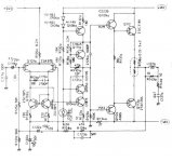
I have try to do a LTspice simulation of this amplifier circuit, but the offset voltage and the bias in this simulation are wrong, anybody can tell me where are my errors in my simulation ?

I include in this post, the circuit image and my simulation file

Thank you

Bye

Gaetan

Attachments

  • luxman.JPG
    luxman.JPG
    52.2 KB · Views: 125
  • Luxmam.asc
    Luxmam.asc
    9.7 KB · Views: 57

Analogue vs DSP crossover

I have been planning to use a DSP crossover with high quality DACs feeding one amplifier per driver in a 3 way active speaker. My first thoughts were whether to use a MiniSHARC or a NanoDIGI - anyone know the advantages of the SHARC?

Anyway, whilst looking for information that compare these two DSPs, I found myself stumbling over several articles that compare analog crossovers with their DSP counterparts. My target (like most people) is to get the most ACCURATE sound reproduction which would imply that the DSP solution is better. Several people point towards the downsides with a DSP solution (even with good DACs) but I just can't see why - is it just 'fear of the new' or are there aspects that genuinely affect the sound quality. For example, does 'perfect reproduction' sound too harsh or something like that?!!

The 375L

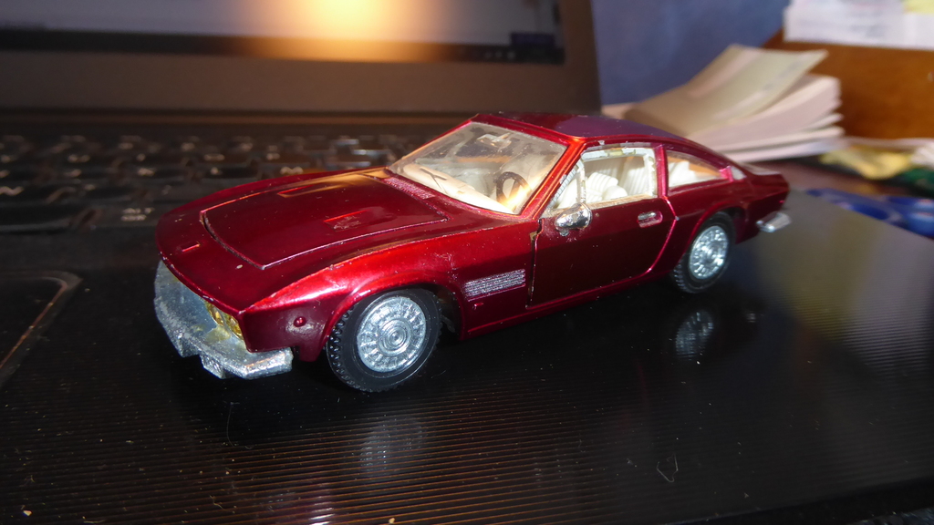
The 375L is the name of a famous Swiss car... 😎

Monteverdi-High-Speed-375L-Fissore-01.jpg


... That I only have in miniature, unfortunately 🙁

YYW6Lb-my-Monteverdi-2.jpg


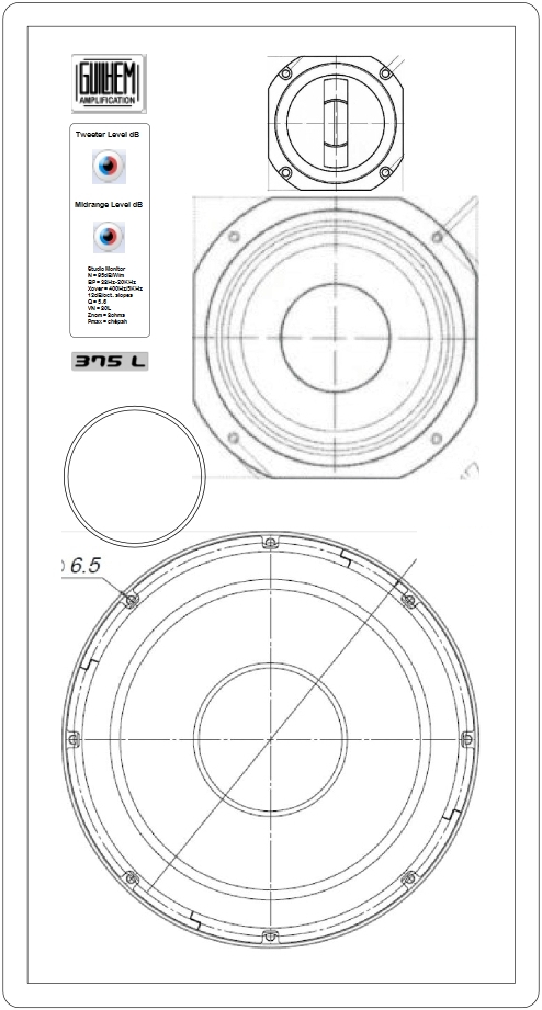
Incidentally, it's the name that I choose for my loudspeaker enclosure project to come - because it's 3-way and 75L. with some Vintage style 🙂

nd1mLb-757-Vintage-Moderne-Convertible-15-08-2020.jpg


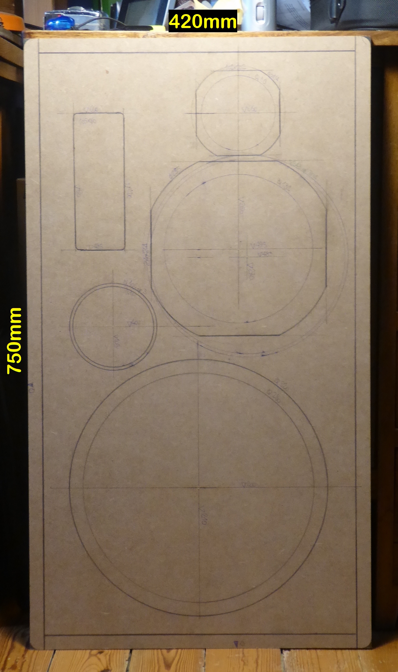
The template :

PKhrLb-P1110731.jpg


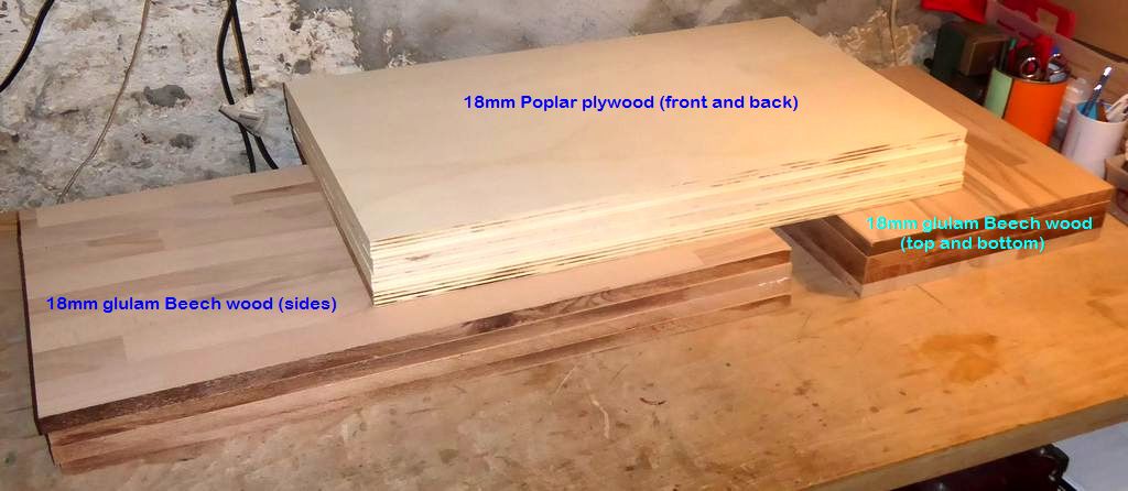
The wood on the bench :

DoZkMb-P1120614.jpg


The start of the construction is scheduled for... Tomorrow 😀

A+!

Please, explain why two complimentary input stages.

I would like to ask why very large public address amplifiers often employ two complementary input stages? Using two different sub-circuits for the input necessitates that the two sub-circuits behave exactly in the same way. My impression, which may be wrong and that is why I am asking, is that, making NPN and PNP transistors to match to a very high degree, is expensive and difficult.

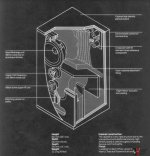
B&W DM2a : need help with stuffing T-line

Hey all,

I recently picked up a pair of B&W DM2a's and am in the middle of rehabbing them. Fortunately all drivers work, the crossover is in fine shape with no EC's, and the cabinets are coming along nicely.

Where I have run into trouble is that, yep you guessed it, some previous owner has messed with the T-line stuffing.

Basically once I removed the front baffle I found the cavity behind the woofer has had all the white fiberglass (?) completely removed. I also found the triple folded felt pad had been unfolded and stapled to the top and all the way down into the throat of the T-line partially blocking it.

Another area of concern is that the white fiberglass (?) in the bottom bend of the first fold of the T-line is very tightly packed. This makes me wonder if the PO took the existing teased stuffing behind the woofer and shoved it down into the bend, or if it was originally this tightly packed.

Some other points of interest: I also found strips of yellow fiberglass sheets (similar to what you would find in a pipe insulation wrap package) laid across the top of the stuffed bend of the T-line at both the inlet and outlet. Also, the rubberized open weave bat that is usually seen at the bottom edge of the front baffle board was also inserted down into the throat of the T-line.

Here's a cut away view of the cabinet and stuffing that shows the intent.
2710492-0d7a7a5a-bampw-dm2a-speakers-2-way-passive-radiator-made-in-the-uk-ex-condition.jpeg

I can easily restore the folded felt mat back to the original intent.
I can also move the rubberized open weave batting back to its original position.
The Yellow fiberglass strips are probably not hurting anything.

Where I need assistance is with the following:

1. What is the original stuffing material behind the woofer?
2. What would be a suitable replacement for this material?
3. Is the 1st bend of the T-line supposed to be very tightly packed?

and
4. any other insights or recommendations are appreciated?

I will post more pics in the next couple posts.

PSU for TPA3255

I am following several threads about the TPA 3255 and come across a lot of questions related to suitable power-supply-units by less experienced users.

This chip can deliver up to 315 watts per channel and has an efficiency of 90% and better , so if we assume 315 watts x 2 = 630 watts which are equal to 90% then the power required to output this is an input of 700 watts. which the PSU has to deliver .

OR LESS ?

YES because the power required depends on the output power you need or want.
If you look up the datasheet of the TPA3255 at this link :

https://www.ti.com/lit/ds/symlink/t...=https%3A%2F%2Fwww.ti.com%2Fproduct%2FTPA3255

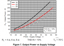
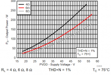
from Texas Instruments you will find a graph of " output power versus supply voltage where you can look up what the voltage you need for the output you want , the range is from 18V to 53.5V D.C.

This is that graph . If you use a slightly higher voltage , say 2 more volts , your output will be perfectly clean provided that your PSU delivers the necesary CLEAN current , which depends on load , type of music played , and a lot of other minor factors .

Now you know the voltage the TPA needs for your output- power.

The current is another story because it depends on the number of channels you have , the kind of music played , but in general terms the PSU should have 20 percent more watts than the sum of the channels to be driven simultaneously , so if you want say 2 channels at 60 watts each which gives 120 multiplied by 120% gives 144 so your PSU should have 150 watts or more , and so on.
This is valid for a class "D" amp , class AB needs a lot more .

With SMPS this should work fine for you provided that it delivers a clean current so consider a filter between the PSU and the amp
With a linear PSU you need high cpacity to avoid sagging rails at 100HZ in Europe and 120HZ in the United States for example.

If you have a linear PSU with a somewhat lower voltage than what you require a good option is to use a boost module to raise the voltage to what you require provided your PSU has the necesary output power and its voltage is between 10 % and about 35 % lowerr than what you need . the allowable booster input current has to be twice the current the amp needs and here as well I recommend a filter between the booster and the amp. Use a booster specified for twice the amps you need as these are quite cheap when bought on AliExpess for examle:

You get this for 10 dollars , or 10,40 euros now .

You can adjust it to the exact voltage you want , and limit the current to whatever you adjust as well.

Attachments

  • 1 output for voltage.PNG
    1 output for voltage.PNG
    41.8 KB · Views: 317
  • 1.1 output for voltage.PNG
    1.1 output for voltage.PNG
    36.5 KB · Views: 1,074

Stetsom ex10500 low supply

Hello everyone. There is an amplifier stetsom ex10500. When turned on, 2 short flashes, one long blink. I remove the resistor R127 and apply ground to the Pic, the amplifier starts up normally and works. Power supply unit 30A 14volt. At the same time, even with a resistor, I do not see a high level. Which way to look, what could be faulty? Before that, one bridge burned down. I replaced Irs, logic, checked all zener diodes and gate resistors. Thanks for the help.

Single touch power on/off switch

Hi guys.

I'm looking to power on my 2x15W JLH from a physical on/off switch in the back and a one-touch button on the front. I want the touch button to turn on the amplifier when I first press it, and turn it off when I press it again.

This is what I've found so far, from eevblog...

https://imageshack.com/i/p9BJywFXj

However, this needs two different touch-buttons, which is both unpractical and uncool. In my head, this modification makes sense and will work, but will it?

https://imageshack.com/i/p3q0gmj5j

I've forgotten enough about electronics, I cannot figure out this myself, therefore I'm turning to you guys, perhaps this can help others as well. 😊

If this is a dead-end, please enlighten me, how can I easily make a simple on/off switch from one impulse switch/touch button. Got relays, bd139/140's, got diodes, caps, resistors... Just doesn't have any dedicated chips or 555's or whatever...

PS: tried to upload the images here first, but was missing a security token of some sort...

Sincerely grateful...

Ben from Norway.

Is it worth Improving phono stage caps? Atoll PH100

Hello,
I got an Atoll PH100 phono stage and was wondering if upgrading these caps will get me some improvements:


-100 pf input ceramic disk caps (these are switchable and when on noise floor increases noticiably)

-220 uf electrolytic caps

-4.7 nf yellow caps

-15 nf white caps


Are the yellow-white caps polyester?


I have compared it to my Rothwell Simplex. Bear in mind the Atoll is brand new, just a few hours of duty and the Simplex is fully burnt in! The Atoll sounds very good but the Simplex has a bit more weight on lower mid frequencies (maybe between 100-400 hz) wich gives a fuller, more sculpted central image... I wonder if the Atoll will get there when burnt in or the type of caps may have something to do.


By the way, do you know what the 2 variable resistors at the bottom of the picture do? I tweaked one and couldn't notice any difference... but I couldn't listen from the listening position while moving the pot, so maybe that's why.
Thanks

Attachments

  • IMG_20210809_120614.jpg
    IMG_20210809_120614.jpg
    621 KB · Views: 658
  • IMG_20210809_120333.jpg
    IMG_20210809_120333.jpg
    403.5 KB · Views: 561
  • atoll-ph-100-phono-preamplifier.jpg
    atoll-ph-100-phono-preamplifier.jpg
    101.1 KB · Views: 626

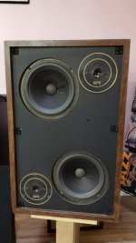
EPI M201 clone

I have just found a really nice pair of EPI 180s and in the interest of diy, I am contemplating building a pair of M201 clones, just for fun.
Even though i have found little in the way of positive comments about the 180, they present a huge soundstage and substantial bass output while having a sweet overall presentation. However they look rather cumbersome in my smallish room and I hear good things about the 201s when placed wide and against the front wall.
The clones can be made from one 4 x 8 sheet of ply or mdf.
Does anyone have knowledge of any internal bracing in the original 201?
Attached is a pic of the 180 which uses the same driver complement as the 201.
Cheers
Peter

Attachments

  • 20170523_185559_resized.jpg
    20170523_185559_resized.jpg
    380.4 KB · Views: 358

  • Locked
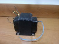
Choke meltdown!

Hi all.

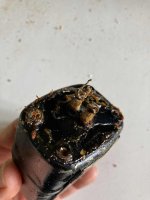
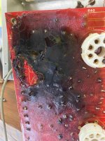
One of my first ever valve projects was a pcb-based PP EL34 with a whole bunch of salvaged transformers. For years, I used an underspecc'd pair of power supply chokes. One day, after maybe a decade of heaps of use, one of them sprang a leak and coated everything in thick oily waxy substance.

1) any thoughts about if this is toxic or if it is just mineral oil?
2) any concerns about just washing it off, replacing the chokes with something more appropriate, and then putting her back into service?

Many thanks!!

Attachments

  • choke1.jpg
    choke1.jpg
    373.8 KB · Views: 470
  • choke2.jpg
    choke2.jpg
    460.2 KB · Views: 474
  • pcb1.jpg
    pcb1.jpg
    775.5 KB · Views: 485

Sundown SFB-8000D

Have one which came in with output FETs hardly working. One was almost shorted but not quite. I clipped a few off the board and the amp started to get a little better.

The output FETs are TO247 but are defaced. Anybody know what these are?

Im also going to replace the drivers ICs, as there are two in this amp; IRS20957S as I believe - scratched off as well; that is IF I can find them. Right now I can only seem to source them from eBay.

Does anyone replace the 6-pin ICs? zxgd3005e6ta as I believe. The problem with these is, they're not available anywhere from what I can tell.

This may be the last Brazilian/clone I work on if I cant find parts.

Thank you in advance.

Resurrect weird version of Z-5500

Hi I have an OLD set of Logitech Z-5500 speakers where its just not functioning anymore. It's the RCA version with a weird PID of 10003301-0445R. I've been searching for a way to resurrect the sub for my own use but I can't find any solutions anywhere. I don't want it to end up in a landfill.

I've bought an adapter meant for PIDS between R200-R635, but the sub just booms and buzzes when I connect it. Mine is obviously wired differently.

I'm not super knowledgeable about hacking electronics, but I have access to tools if I could just figure out what to do. Can anyone help me?

Alpair 7ms enclosure recommendation

Hello

I am looking for some thoughts on an enclosure for the 7ms driver. I already have a pair of the drivers but am a bit stuck on a design.

Goals / criteria
- Under ~12" x ~12" footprint
- Room size is about 250 sqft
- Able to be very close to / up against the back wall
- Floor standing or bookshelf is ok
- Ideally used without a subwoofer
- FAST / WAW ok as long as a speaker level passive crossover can be used
- Driven from a 50-100 watt home theater type receiver

Any ideas on something that would meet the above?

Thanks!

Chassis or dedicated heatsink for MOSFET

Hi,

Is it OK to use the amp chassis as heatsink for discrete semiconductors like B+ voltage regulating MOSFETs (insulated package, like TO-220F), or should I always put a dedicated heatsink? I'm not looking at extreme cases like 6C33-based amps, which get extremely hot, but something based on 6L6GC/EL34 in class AB. Any advice is much appreciated!

Thanks,

Jose

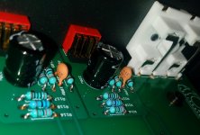
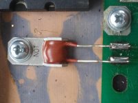
Help Please. Can't figure out what this component is.

Hello DIY People,

Can somebody help me figure out what this part is please. There are two of them, one for each channel, and they are mounted to the heat sinks right next to the power and output transistors of a McIntosh MC425 audio amplifier. It looks like a cap but there are no specs on it so even if it is a cap I don't know how to find the specs for it so I can either test or replace it.

I spent the last few days looking for a schematic for this amp so that I could figure out what this part is. But I can't find a schematic for this amp. I found some McIntosh amp schematics, just not for this one.

Here is the picture of the part.

how can i find out what this is and the specs for it so I can test it.jpg

FS: Frugel-Horn Mk3 Pro build, incl outriggers and speaker terminals NEW

Selling a pair of professionally CNC'ed Frugal Horn FH3's. The bezel is machined to accept the Fostex FE126En drivers. Includes outriggers, spikes and speaker terminals.
Built from high quality marine grade Baltic birch.
Asking $350. Shipped at buyers expense, local pickup in DFW or I can deliver to Houston next week.


AMP Setup Recommendation

New to Amp boards here and need some suggestions and help!

Plan on building a 2.1 speaker setup, and have got some requirements on mind for the amp:

1- has > 70w x 2 channels
2- has >= 100w subwoofer channel
3- has Bluetooth module

Found https://www.amazon.com/AOSHIKE-DC12V-24V-Subwoofer-Amplifier-Bluetooth/dp/B07BKYL3GC/ref=sr_1_5?dchild=1&keywords=tpa3116+amp&qid=1629042633&sr=8-5 which satisfies 2,3 but its only 50w per channel.

Couldn't find any "Cheap" boards that satisfy all 3 requirements that I have.
Can I use one of this in conjunction with one of that for the ultimate 2x100 + 100w? How would I go about connection both amps to work as one single unit?

Thanks in advance!

horn vs xover issue

Hello good people,

I'm relatively inexperienced at this stuff and a little confused by what i'm running up against. My buddy gave me a JBL floor monitor which was not working. I pulled it apart, the woofer worked fine if i used a tone generator on it, the horn seemed to work fine similarly, so i assumed the two way crossover had an issue. I replaced it with one from amazon, and had the same issue, but i could hear that there was audio coming down that line with an induction wand. I tried several other speakers that should have been able to replicate high end frequencies and got nothing. I then took the leads from the x-over to the woofer and put them to the horn and it made high end noise. At this point i assumed i got a DOA crossover and had amazon replace it. New crossover is having the same issue. If i run full range to the horn, it functions ( i know not to leave it like that) Anyone know what might be going on here?

I did look through the forums for a similar issue, but didn't find one. Apologies if i missed it.

Thanks
telfer

Speaker: JBL JRX100
horn: JBL2412h-1
Woofer: JBL M112-8 (8 Ohms)
original crossover jrx112M
new crossover(s) EMB CX-5
Projects by fanatics, for fanatics
Get answers and advice for everyone wanting to learn the art of audio.
Join the Community
507,637
Members
7,881,749
Messages

Filter

Forum Statistics

Threads
405,930
Messages
7,881,749
Members
507,637
Latest member
noname203