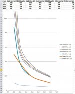
Here's a chart from DSL giving port location horn loading cutoff for the SH-50, a 50x50 conical.

I need the same chart for a 60x60.
(and would really like to learn how to generate them for any size pattern...via math or maybe via hornresp ?)
Thanks, Mark
I need the same chart for a 60x60.
(and would really like to learn how to generate them for any size pattern...via math or maybe via hornresp ?)
Thanks, Mark
Hi mark100,
I had the same question a while ago.
I am by no means a guru, but my understanding, by reading the text is that Tom calculates the distance along the axis of a conical horn where the area doubles. He than uses the calculated distance to use the fc of an exponential horn with the same doubling area over distance.
I had generated curve(s) for different included angle based on the theory, and although the curve(s) had similar shape, they were not the same as Tom's.
Patrick Bateman posted a set of curves for different angles (attached), again different from Tom's and mine, but he ignored my question how he obtained them. Perhaps you can ask him with a better result?
Kindest regards,
M
P.S. I have the code I used if you want it, but it is written in Maple. I think that you raised my curiosity, so I will re-install Maple and revisit the issue. I also have Tom's curve digitized at certain points, if it would be helpful to you.
M
Attachments
Last edited:
Thank you very much mefistofelez 🙂
That's exactly the information trail i'm trying to hunt down.
I got the same sense that the conical horn area-doubling was being translated to an exponential horn somehow, but got lost even thinking about that.
Thx for the code offer. I wish i was more fluent with various codes; guess too much time spent back in PC's primitive days working with CPM, Basic, even assembly/machine language, made me swear off programming forever. Lol
I'd love to find some straight-up math though...anything i could put in Excel for instance.
Nice graph...will study !
Hi Mark,
I seem to recall there being a way of using hornRESP to show the flare rate at the points where you place the ports. I think you had to change the CON to EXP on the section you want the flare rate for.
Hopefully this post will prompt somebody who knows hornresp better than me to let you know exactly how to do it.🙂
Not exactly the graph you are after, but could help.
Cheers,
Rob.
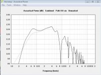
Just checked on my old laptop, yes if you change the s2 / s3 length box to Exp it shows the flare rate.
On my 50x50 test box I modelled a pair of 10FE200 7" from the throat. This gave a flare rate of 171Hz. It kind of shows why DSL does the rear port on the bass drivers, The port starts to take over almost where the horn stops supporting the driver (attached pic shows with / without rear port.
Cheers,
Rob.
Attachments
Hi Rob, thanks for that.
Your recollection about Hornresp, COC to EXP, has rumbled around in my mind too.
I now remember trying that a couple of years ago when i first started in on MEHs.
Your observation about needing rear ports on bass drivers squares with my measurements.
It's been hard to get bass extension without them, even with main ports almost at any distance from the throat.
Yes, very true for conical horns useful for covering more than a very narrow pattern.Your observation about needing rear ports on bass drivers squares with my measurements.
It's been hard to get bass extension without them, even with main ports almost at any distance from the throat.
Tom Danley wrote in the article in the OP:
"In essence for every point along the axis of a conical horn there is a different expansion rate and, in turn, a different low frequency cut-off."
From Horn Theory: An Introduction, Part 1 By Bjørn Kolbrek:
"The throat impedance of an infinite conical horn is…identical to the expression for the radiation impedance of a pulsating sphere of radius x0.
The throat resistance of the conical horn rises slowly…At what frequency it reaches its asymptotic value depends on the solid angle Ω, being lower for smaller solid angle. This means that for good loading at low frequencies, the horn must open up slowly.
.. a certain minimum mouth area is required to minimize reflections at the open end. This area is larger for horns intended for low frequency use (it depends on the wave- length), which means that a conical horn would need to be very long to provide satisfying performance at low frequencies. As such, the conical expansion is not very useful in bass horns. Indeed, the conical horn is not very useful at all in applications requiring good loading performance, but it has certain virtues in directivity control."
Considering the main goal of the conical MEH (multiple entry horn) is to provide "certain virtues in directivity control", the minimum distance to the throat possible for all the driver's output to sum within 1/4 wavelength from each other outweighs a few dB peak above "a different low frequency cut-off".
Art
I'd love to find some straight-up math though
Y = Y1 + (Y2 - Y1) / X12 * X
m = Ln(Y / Y1) / X
fc = m * c / (2 * Pi)
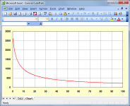
For the attached example:
Y1 = Half-width at conical horn throat = 1 cm
Y2 = Half-width at conical horn mouth = 50 cm
X12 = Conical horn axial length = 100 cm
The cutoff frequency at an axial distance X = 30 cm from the horn throat is given by:
Y = 1 + (50 - 1) / 100 * 30 = 15.7 cm
m = Ln(15.7 / 1) / 30 = 0.0918 (rounded to 4 decimal places)
fc = 0.0918 * 34400 / (2 * Pi) = 502.60 Hz
Attachments
Thanks for that.
so "c" is speed of sound in cm/sec
I suppose fc is where response is 6? db down relative to asymptotic value?
Now I wonder why this is true. Does formula derive from one for acoustic Z?
so "c" is speed of sound in cm/sec
I suppose fc is where response is 6? db down relative to asymptotic value?
Now I wonder why this is true. Does formula derive from one for acoustic Z?
Yes, very true for conical horns useful for covering more than a very narrow pattern.
Tom Danley wrote in the article in the OP:
"In essence for every point along the axis of a conical horn there is a different expansion rate and, in turn, a different low frequency cut-off."
From Horn Theory: An Introduction, Part 1 By Bjørn Kolbrek:
"The throat impedance of an infinite conical horn is…identical to the expression for the radiation impedance of a pulsating sphere of radius x0.
The throat resistance of the conical horn rises slowly…At what frequency it reaches its asymptotic value depends on the solid angle Ω, being lower for smaller solid angle. This means that for good loading at low frequencies, the horn must open up slowly.
.. a certain minimum mouth area is required to minimize reflections at the open end. This area is larger for horns intended for low frequency use (it depends on the wave- length), which means that a conical horn would need to be very long to provide satisfying performance at low frequencies. As such, the conical expansion is not very useful in bass horns. Indeed, the conical horn is not very useful at all in applications requiring good loading performance, but it has certain virtues in directivity control."
Considering the main goal of the conical MEH (multiple entry horn) is to provide "certain virtues in directivity control", the minimum distance to the throat possible for all the driver's output to sum within 1/4 wavelength from each other outweighs a few dB peak above "a different low frequency cut-off".
Art
Thx Art, good collection of relevant summary points....
1/4 WL ruling build designs, it is 🙂
If i want lower woofer extension, i'll get better at designing in reflex ports....
Y = Y1 + (Y2 - Y1) / X12 * X
m = Ln(Y / Y1) / X
fc = m * c / (2 * Pi)
For the attached example:
Y1 = Half-width at conical horn throat = 1 cm
Y2 = Half-width at conical horn mouth = 50 cm
X12 = Conical horn axial length = 100 cm
The cutoff frequency at an axial distance X = 30 cm from the horn throat is given by:
Y = 1 + (50 - 1) / 100 * 30 = 15.7 cm
m = Ln(15.7 / 1) / 30 = 0.0918 (rounded to 4 decimal places)
fc = 0.0918 * 34400 / (2 * Pi) = 502.60 Hz
Thank you kind sir !!! You are are blessing to us all, Mr McBean.
Exactly what i've hoped for 😀
A little bit of playing around in Excel this morning has already convinced me not to look for any woofer efficiency gains from port placement locations (on the conicals)
so "c" is speed of sound in cm/sec
In my example, yes, because the horn dimensions are given in centimetres.
I suppose fc is where response is 6? db down relative to asymptotic value?
The cutoff frequency fc at any point along the conical horn is determined by assuming an exponential horn rather than a conical horn up to that point, and simply calculating the cutoff frequency of the exponential horn. While the chart might look nice, I am not sure how meaningful such results actually are, based on the way that they have been calculated. Attachment 1 refers.
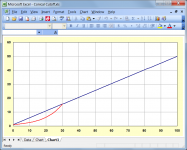
Does formula derive from one for acoustic Z?
The cutoff frequency of an exponential horn really only applies in the infinite case, and is the frequency at which the resistive component of the throat impedance drops to zero. In Attachment 2 the cutoff frequency is 100 Hz.
Attachments

A little bit of playing around in Excel this morning has already convinced me not to look for any woofer efficiency gains from port placement locations (on the conicals)
Personally I would just use the Multiple Entry Horn Loudspeaker Wizard in Hornresp, and simply adjust the sliders to alter the positions of the drivers until the performance was optimised to my satisfaction.
Y1 = Half-width at conical horn throat
Y2 = Half-width at conical horn mouth
Just to clarify - because the calculations are based on an axisymmetric conical horn model, to avoid any confusion I should have perhaps used "radius" rather than "half-width" when referring to the Y parameters.
In my earlier example, at an axial length X of 30 cm the radius Y is 15.7 cm, giving a cross-sectional area of 774.4 cm^2.
The actual physical horn does not necessarily have to be circular, at 30 cm it could have a rectangular cross-section of say, 24.2 cm x 32 cm.
Personally I would just use the Multiple Entry Horn Loudspeaker Wizard in Hornresp, and simply adjust the sliders to alter the positions of the drivers until the performance was optimised to my satisfaction.
Sure, that does sound easier 🙂
And thx for the follow up on radius vs half-width.
That was how i built my simple Excel sheet yesterday, converting rectangular area to a circular area. Confirmation is always nice.
- Home
- Loudspeakers
- Multi-Way
- Need horn guru help: