I found (and ordered) a loudness PCB on which the capacitors (4 pieces of 2nF and 4 pieces of 0 .033 uF) and resistors were "calculated" for a 50k Ohm volume potentiometer.
I am currently using a very good sounding 10K TKD 2CP-2511 log pot in my passive preamplifier.
There is also an Audio Note 100k log pot "in reserve".
My questions are: what happens if I connect the 10k Ohm or the 100k Ohm volume potentiometer to a pcb "designed" for a 50k Ohm pot, without replacing resistors or capacitors?
Or, as far as I know, for a 10k Ohm pot I would have to change the resistors to 1/5 value and the capacitors value to 5x. If this analogy is correct, when I am using a 100k pot do I have to change the resistors value twice of original and the capacitors value to the half?
Yes, that's exactly how the components scale. Capacitor impedance is inversely proportional to capacitance, for any given frequency.
100k pot might increase the noise floor noticably over the 10k pot, depending on levels, gains and speaker sensitivity. What is the output impedance of the source(s) and the input impedance of the power amp?
100k pot might increase the noise floor noticably over the 10k pot, depending on levels, gains and speaker sensitivity. What is the output impedance of the source(s) and the input impedance of the power amp?
Hi Mark,
thank you for your answer!
Source 1: CA Sonata NP30. I use this almost exclusively for listening to background music, that is, listening to online radios. No output impedance data found.
->
Source 2 or main source: 12AU7 tube buffer preamp with CSR8675 chip. It used to have a "small" volume pot in this too, but I've taken it out a long time ago and wired it directly. I use this when I "sit down to listen to music". The reason: thanks to the BT5 chip, I can stream lossless music from my laptop via LDAC encoding via Ubuntu + Foobar.
For impedance data I found these: Audio input: <2Vrms Impedance: >10KΩ
Audio output: <3Vrms Impedance: >10K Ω
->
The following element in the chain: Musical Fidelity X-10v3 (with MF X-PSU v3) tube output buffer. It has Rock Grotto upgrade components and other mods.
Input impedance: 470k Ohms
Output impedance: <33 Ohms
->
Next in line is the passive preamp, currently with the TKD 2CP-2511 10k Ohms pot.
And there is a 2m RCA cable between the MF X-10v3 and the passive preamp. In this connection sequence, there is no buzz due to the long RCA, if the passive preamp is in front of the X-10v3, it would be a buzz in the SS power amplifier. (think cable capacitance is the reason)
These were the fixed elements.
And the endpoints that are connected to the passive preamp when which one I feel like listening to:
1: SS amp: Musical Fidelity X-P200 power amplifier. Input impedance: 27k Ohms
2: Tube (SE?) amp: APPJ PA1601a (also slightly modified). Input Impedance: 10K ohms
3: And there’s a Tripath TA2020 chip little amp just coming.
The primary question is what happens if I use 10k instead of the recommended (designed for) 50k pot?
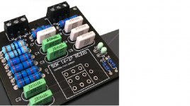
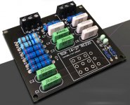
POST-THE-SCHEMATIC 😉a loudness PCB on which the capacitors (4 pieces of 2nF and 4 pieces of 0 .033 uF) and resistors were "calculated" for a 50k Ohm volume potentiometer.
You supply tons of not so useful data, such as brands / models / tubes / DACs , etc. but not the most important one.
Please do.
As a side note, not sure how a bare bones minimalistic Audio device such as a "passive preamp" ( a Pot in a box) mates with a Loudness circuit or any other added kludge, doesn´t that ruin the minimalistic Philosophy?
The minimalist design is, of course, upset. But for me, it’s just a hobby, and obviously it’s also clear from sharing useless information. For this, as well as for the unprofessional attitude, I apologize to everyone in advance.
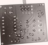
For the time being, instead of a schematic, I can only provide the following images, so far I know so much about switching.
For the time being, instead of a schematic, I can only provide the following images, so far I know so much about switching.
Attachments
- Home
- Amplifiers
- Solid State
- Loudness pcb with 50kOhm design, could I use it with 10k log pot?