Biasing a Heathkit A8-A (6L6) amp

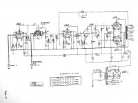
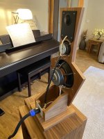
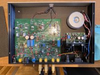
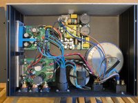
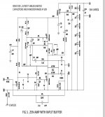
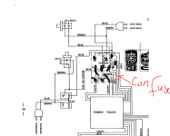
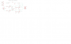
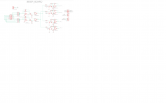
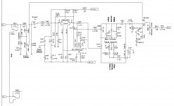
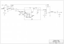
I'm resurrecting an old Heathkit A8-A amp (see attached schematic) and I have a question about plate current in the two 6L6Gs (which I believe to be original 50s vintage; original spec is 6L6 or 6L6G). It has been completely recapped and all out-of-spec resistors have been replaced.

Plate voltage on the 6L6Gs is 392V; cathode voltage is 26.7V. As measured across the output transformer, the plate current is 53 mA on one tube (8V, 150Ω winding) and 47 mA on the other (7.7V, 165Ω winding). The 10W cathode resistor measures at 254Ω. Measured current across this resistor is 105 mA (26.7V/254Ω), or 52.5 mA per tube.

As I understand it, the recommended bias point for an AB amp is 70% of rated power (I=.7(P/V), or .7(19/392)), which would be ~34mA. If that's correct, the observed measurements seem high.

Questions:
- Do I understand this correctly? Is the plate current higher than optimal?
- Assuming the current is higher than you'd like, what's the best way to lower it? It seems to be a choice between lowering the plate voltage (adding an inline resistor) or bumping the cathode resistor to a higher value.
- If I switch to a pair of 6L6GC tubes (rated at 30W), would that bring things back into spec? If everything else stays the same, that would put the 70% point at 54 mA, which is very close to where it is now.

Answers? Questions? Comments? Insults?

Thanks.

Attachments

  • Heathkit A-8A schematic.jpg
    Heathkit A-8A schematic.jpg
    144.5 KB · Views: 281
  • 6L6G.pdf
    6L6G.pdf
    499.3 KB · Views: 93

Genesis profile

Hello,

I get an amp Genesis Profile 4. However it is not working, I open it and all input caps were dead.
So I have changed them. Next issue is that there are 5 diodes which are also blown. I would like to replace them but I have no service manual and also I can not find any marking on them.
I believe that it is not Zener as no voltage is writen on it or PCB, I have found on PCB place for another diode and on PCB is mark for diode and 12V. So I believe that maker marked Zeners with voltage on PCB.

Based on this I believe that I am loking for standard diode but I do not know which.
Does anyone know it or service manual would be much welcomed 🙂

Thank you

Attachments

  • IMG_20210830_165037.jpg
    IMG_20210830_165037.jpg
    403.7 KB · Views: 96
  • IMG_20210830_142528.jpg
    IMG_20210830_142528.jpg
    752.6 KB · Views: 91
  • IMG_20210901_133852.jpg
    IMG_20210901_133852.jpg
    479.7 KB · Views: 87
  • IMG_20210901_185125.jpg
    IMG_20210901_185125.jpg
    160.4 KB · Views: 90
  • IMG_20210901_185141.jpg
    IMG_20210901_185141.jpg
    68.9 KB · Views: 86
  • IMG_20210901_185947.jpg
    IMG_20210901_185947.jpg
    642 KB · Views: 60

What spec are the light bulbs?

Eminence Crossovers incorperate "aviation light bulbs" for current protection. I like the old-school idea unfortunetly I live in the UK and buying from Eminence is problematic. There must be other sources. In any case they are not magic. How do I know if the bulbs are correct for my speaker?

I'm thinking that pushing 500W through a 4 ohm driver using P= I²R gives me a current of 11.2A and then V=IR gives me a 45V

Armed with that information, how/where can I go shopping?

JVC JR-S201 amplifier repair troubleshooting

Hi all, I am new to the forum and, well, I'm here because I made, let's say, a careless mistake. While swapping out the lamps in my JVC SR-201 receiver before having my tea in the morning, I put the wires down for a moment (doh!), and before I knew it, shorted the circuit between the two lamp connectors (pins 911 and 914 on the circuit diagram, square E2). I got some smoke and a burnt out resistor (R805 on the amplification board) and a fuse for my troubles. After replacing the fuse, the amp now will not put any signal out, and it generates a significant amount of heat and smoke if I try to run it even without a load attached, again from that resistor R805, which I've also since replaced. I have tested the transistors on the main board less-than-systematically, and I haven't found any of them to give zero or infinite readings on the ohmmeter.


My question is whether anyone has any useful suggestions from here as to what I might have fried with my carelessness - the service manual is here if it's any help, with the circuit diagram on pp 31-32. I'd appreciate any help, as I am about at the point where I'll just get rid of the thing if I can't fix it.


Thanks for any help you can provide in advance!
FT

Yet another treatment question.

As of now I have some simple diy absorption bass traps in my main wall corners. Without doing measurements it seems like it helped tame some of the boomyness? of my small room.

I need to add some more album storage to my little listening den and was wondering about building some bookshelves with 2" of absorption built into the backs to place in each corner in place of the fabric wrapped 2" Rockwool 60 that's up there now.

Basically build a 15ish" deep bookshelf case, with a 13" deep shelf, leaving 2" or so in the back where I can insert my fabric wrapped Rockwool so that it becomes the backing of my bookshelf. These bookshelfs will be mostly filled with albums blocking almost all of the front of the absorption material, but I would leave them and inch or two away from the wall with completely exposed (wrapped in grill cloth) absorption material on the backs.

Is this a terrible idea?

Would it work?

Huge waste of time?

Just build regular bookshelves to put in the corners and don't fool with adding Rockwool to the backs?

Either way the panels are probably coming down and bookshelves replacing them.

KRELL FPB 400CX rear breaker

So, my 400CX is tripping the rear breaker.

I have replaced a number of PNP and NPN transistors on both output boards as they were testing kaput, plus a bank of .47 and .2 ohm resistors that tested open.

This has made no difference.

The workflow is as follows

Power On - Standby LED illuminates

Button Press - Reg LED illuminates then Bias then click breaker

So all LED illuminate which for debugging is not helpful, I am going to check for when the high signal occurs on the breaker, as this is clearly being sent high (or low I am not sure if it is active LOW or HIGH but I will tell)

It would be good to understand what conditions the MC tells the breaker to trip, there is mV of DC on the terminals even when it trips, so it is not that, I do not know any of the other conditions.

Any help is as always appreciated.

Kiitos

Björn

Two layer versus four layer PCBs

I'm asking for opinions on whether a four layer PCB will work better than a two layer PCB for audio applications like power amplifiers. A four layer board would have a ground plane.


I've come across varying opinions, without any solid answers.


I'm a retired IC designer beginning to dabble in audio. I've designed switching power supply chips, both buck and boost converters. It was critical that these chips be used with carefully designed four layer boards because of the high frequency currents circulating between the chip and external components. Sloppy design resulted in failure, and two layer PCBs would not work at all.


I have no real experience with designing boards for audio, so any comments will be appreciated.

Issues with Pi 4, DACs and VLC

I'm trying to resolve the issue with DACs connected over USB to the Rapberry Pi 4. I've tested three DACs so far: Alien DAC (based on PCM2702), Topping E30 (based on AK4493) and Khadas DAC (based on ES9038Q2M).

Sometimes when I use VLC for audio playback and when either skip to a different time in the track or switch to a new track the audio drops - no output. That very often happens with Topping and Khadas DACs. That never happens with Alien DAC. Here is the VLC log when that issue occurs:

Code:
flac debug: emulated sync word
main debug: Buffering 0%
main debug: Buffering 2%
main debug: Buffering 4%
main debug: Buffering 6%
main debug: Buffering 9%
main debug: Buffering 11%
main debug: Buffering 13%
main debug: Buffering 15%
main debug: Buffering 18%
main debug: Buffering 20%
main debug: Buffering 22%
main debug: Buffering 25%
main debug: Buffering 27%
main debug: Buffering 29%
main debug: Buffering 31%
main debug: Buffering 34%
main debug: Buffering 36%
main debug: Buffering 38%
main debug: Buffering 41%
main debug: Buffering 43%
main debug: Buffering 45%
main debug: Buffering 47%
main debug: Buffering 50%
main debug: Buffering 52%
main debug: Buffering 54%
main debug: Buffering 57%
main debug: Buffering 59%
main debug: Buffering 61%
main debug: Buffering 63%
main debug: Buffering 66%
main debug: Buffering 68%
main debug: Buffering 70%
main debug: Buffering 73%
main debug: Buffering 75%
main debug: Buffering 77%
main debug: Buffering 79%
main debug: end of audio preroll
main debug: Buffering 82%
main debug: Buffering 84%
main debug: Buffering 86%
main debug: Buffering 89%
main debug: Buffering 91%
main debug: Buffering 93%
main debug: Buffering 95%
main debug: Buffering 98%
main debug: Stream buffering done (4086 ms in 29 ms)
main debug: Decoder wait done in 0 ms
main warning: playback too early (-96174): down-sampling
main warning: playback too late (110306): up-sampling
main warning: playback way too late (203080): flushing buffers
main debug: inserting 51591 zeroes
main warning: playback too late (72377): up-sampling
main warning: timing screwed (drift: 165441 us): stopping resampling
main warning: playback way too late (258300): flushing buffers
main debug: inserting 51972 zeroes
main warning: playback too late (80854): up-sampling
main warning: timing screwed (drift: 173984 us): stopping resampling
main warning: playback way too late (270229): flushing buffers
main debug: inserting 51454 zeroes
main warning: playback too late (72708): up-sampling
main warning: timing screwed (drift: 163608 us): stopping resampling
main warning: playback way too late (260490): flushing buffers
main debug: inserting 51393 zeroes
main warning: playback too late (70476): up-sampling
main warning: timing screwed (drift: 162990 us): stopping resampling
main warning: playback way too late (257217): flushing buffers
main debug: inserting 51775 zeroes
main warning: playback too late (78053): up-sampling
main warning: timing screwed (drift: 173214 us): stopping resampling
main warning: playback way too late (264664): flushing buffers
.....
The last messages repeated over and over again until the playback resumes to normal when I manually switch the audio track.

Probably anybody else faced the same issue and knows how to fix it?
Thanks!

How do I thermally bridge two heat sinks?

I have a DISPANTE 4U cabinet laying around, with very large heat sinks that I would like to use as an enclosure for a large MOFO Power AMP. It would pump out 20 watts at an idle current of 2.5 amps ( per channel )


The MOFO uses one power transistor / channel that requires a heat sink.
The Dispante 4U uses two equal sized heat sinks per side ( channel ).


Is there a reasonable way to thermally bridge the two heat sinks together, to form one large heat sink?

Rockford P400X4

Good afternoon

I would like mosfet to use the rockford p400x4 in the output since I have none at the moment I just bought it and it would come if they q1, q3, q2, q4, q5, q7, q6, q8 and if the regulator q1002 is equal to q1003 or what goes in its location r27 is missing but must be equal to r26.

I appreciate the information you can provide me

Hifonics txi 1500d output transistor !!

Hello..I have a hifonics txi 1500d broken..Amplifiere was burned and i changed the tl494 , driver transistor,power suply transistor ,and driver hip4080, .Now the power suply work good.the problem is at output transitor because when put the power suply on the amplifier , 3 transistor from photo are very hot,in few seconds are at 100 celsius degrees.
If the voltage remains coupled transistors are destroyed(only 3 pcs).I wil put a photo for see.,.i use irf1310 all output transistor.
I wait the sugestion,what i must to check:|thank you anticipate:|😕😕

Attachments

  • DSC_8011.jpg
    DSC_8011.jpg
    802.9 KB · Views: 464
  • tranzistori hot.jpg
    tranzistori hot.jpg
    132.5 KB · Views: 412
  • DSC_8016.jpg
    DSC_8016.jpg
    681.5 KB · Views: 421

ETI-466 300W Amplifier

Hi:

I am wondering if anyone has experience and success building the ETI-466 300W Amplifier:

http://users.otenet.gr/~athsam/power_amp_300w.htm
or
http://www.alphalink.com.au/~cambie/ETI466Web.htm

I've read a couple of threads on here already and would like to hear from other members who have experience with this design.

I've been working on the module for some time now and after some research on the internet, it appears mine is suffering from high frequency oscillaion in the output/driver stage.

Anybody experience the same problem with this design? Any ideas on how to correct it?

Thanks,

Derek

[FS - UK] Linkwitz LX521 system - please contact me if interested

I'm still a bit unsure if I want to part with these, however I have too much audio equipment and several pairs of speakers hanging around so something needs to go (to maintain matrimonial harmony!).

Looking for £2500

These are phenomenal speakers, constant directivity, true full range (20Hz to 20Hz). I tested them against Wilson Watt Puppies, KEF R3, PMC twenty.25, Troels Gravesen 3WC-15 and these where by far my favourites. You'd have to spend some serious money to equal these if purchasing a traditional commercial speaker.

The only thing you need to be aware of is that these are open baffle speakers - you need to be able to position them out into the room by 1.25m to have the best sound quality. Recommended room size is 25m2 or larger - these speakers are capable of serious volume levels without distortion!

LX521 Description

These have been built exactly to the LX521.3 specification. Original build manual will be provided with the purchase.

Included in this auction:
Pair of LX521 speakers - mdf with oak style veneer. 12 seas drivers installed
(see:
Madisound Speaker Components ... 4-way-kit/)
Sommer Elephant 8 core speaker cables terminated with neutrik plugs - I have a number of pairs, including some 4-5m long. Should be enough for all siting options.
Pair of amplifiers (each amplifier containing three channels of amplification: a stereo LM4780 feeding mid and tweeter, and a single channel Hypex feeding both woofers)
Analogue signal processor (ASP.3) that takes analogue output (XLR or RCA) from your source and splits it to each amplifier channel.

The above is a full active and working system, just add your source/preamp.

Attachments

  • IMG_1199.jpg
    IMG_1199.jpg
    139.1 KB · Views: 346
  • IMG_1197.jpg
    IMG_1197.jpg
    116.7 KB · Views: 335
  • IMG_1198.jpg
    IMG_1198.jpg
    133.4 KB · Views: 329
  • IMG_1200.jpg
    IMG_1200.jpg
    149.7 KB · Views: 329
  • IMG_0200.jpg
    IMG_0200.jpg
    148.6 KB · Views: 327
  • IMG_0153.jpg
    IMG_0153.jpg
    223.4 KB · Views: 203
  • IMG_0149.jpg
    IMG_0149.jpg
    201.8 KB · Views: 201

WTB or Trade for Twisted Pear X-BOSOZ PCBs (Twisted BOSOZ)

Looking for one or two X-BOSOZ Preamp PCBs. I don't need but will take the PS PCBs as well if you have the complete set. I have a complete set of all of Mark Johnson PCBs that I had made from the gerber files for the M2X and DIY VFET amp front end cards as well as the Quasimodo V4.

If you have the X-BOSOZ boards to spare, I am sure we can make a deal.

Regards,

Roy

Output transformer questions

I have a pair of single ended output transformer from electraprint. They are slightly ugly, the laminates have rust on them, and the bells are scratched. They are not too bad, so I would like to know if it is worth doing some “improvement” on them.

1. Can I dismantle the 4 bolts holding the laminates together? I seem to remember reading performance of the air gapped transformers will be affected if they are dismantled, but I don’t remember where and why.

2. These transformers do not have a ground connection. I have come across ground connection from OPT that is basically a wire soldered on the outermost laminate. I would like to know if this is a good practice or no better than grounding the end bell.

3. I am aware that there are heat resistant paint, but I have not been able to find one that is not a spray paint. I wonder how well do regular paint stand up to tube heat, say about 2” from EL84 or 6V6.

4. Is it preferable for the bell side to face the tube heat, as opposed to the laminate side? Or it does not matter enough either way.

  • Locked
Chassis and customization for 5ea. Hypex NC400s and SMPS

I am interested in the Pesante or Slimline Chassis to install 5ea NC400 and 5ea SMPS600N400 in. According to the guys at Hypex, I can install these vertically. To do so would require Risers with custom milling to match their mounting points. These are not standardized to match the existing 10x10mm grid.
Another option could be laying them fla: again, custom milling on the baseplat or bottom of chassis itself would be required.


This would be the main element allowing me to use your product instead of any of the other DIY Chassis options out there. I'm hoping that customized risers will be able to be produced and would like to discuss further with you!


Many thanks,
R

Testing large oil capacitors

I'm in the process of repairing a piece of equipment with ferroresonant transformers supplying some large linear regulators. The transformer hums pretty loudly for a brief instant before the supply shuts off due to undervoltage protections kicking in.

The caps are 20uf at 660vac and 10uf at 660vac. They measure within spec on a handheld meter but that's hardly representative of their in circuit use. I connected them to a regulated high voltage dc supply and watched the current on my 5.5 digit bench meter. The leakage current is unreadable, it looks below the noise floor of my meter. How can that be? They also seem to hold a charge just fine. For reference a small 0.1uf oil cap shows steady leakage in the microamp range which is expected. I just can't believe these old caps have an undetectable amount of leakage. 😕

SOTA 11R experiences

Hi Everyone,

A while back a bunch of us were able to pick up some excess SOTA 11R drivers. At the time there were no TS specs available but we were told that they were similar to the pluvia 11 drivers. I got tied up finishing up some electronic projects (F4, F3 FE preamp, BA 2018 pre, phidecca dac) so they have been sitting gathering dust on my workshop bench in the meantime. I know that there were some TS parameters posted on fresh, not broken in drivers. What I am interested to hear is :

1.) Are there any broken in TS parameters available ?

2.) What have folks built with them ?

3.) What are the opinions as to their sound quality ?

I do not have the ability to test for the TS parameters myself but I'm looking to do something with my pair. If they truly are like the pluvia 11, the "King of the swingers" box posted by Scott looks appealing, a simple easy build that can get some bass from a full range design. I'd appreciate any feedback.

Thanks,

Paul

Augmented passive radiator

I'm thinking of building a subwoofer for home theater use.
I'd like a low f3 (about 25Hz or less) in a small cabinet (about 50 to 60 liters). (but that's probably what everbody wants in a HT sub)

I've done some research and I came across the Augmented Passive Radiator (APR) in Dickason.
An APR is a system with two passive radiators with different size and two chambers. The f3 is half an octave lower than a normal passive radiator with a slightly more volume (20%) of the cabinet.
There's not much info on this forum or the internet about DIY APR's.

Is there anybody out there with some expirience on building an APR?
Or does someone have some more info/examples on DIY APRs?

Hum by induction on preamp output cable - is that a thing?

Hi,

I am trying to track down a hum problem with my phono-preamp/poweramp combination. From the surface, it sounds like a "normal' ground/earth loop and most everyone keeps telling me to just figure out where the wrong ground connection is. Based on my experiments I strongly beleive that it is something else. However, I have not found any mention of such a problem before. That may have to do with my lack of expirience. Also, please forgive if I'm getting some terminology wrong as english isn't my first language and most things that I know about electronics I have learned based on German language instruction.


The preamp is based on a kit from puredynamics.com - I'm also in conversations with Georg Ruppert, the designer but we haven't quite figured this one out yet so I wanted to try if I could get some additional insights/ideas here.
The basic design is a JFET/E88CC cascode input followed by cathode follower, RIAA equalization and a second stage based on another E88CC double triode. The second stage uses negative feedback and the overall gain of the preamp can be adjusted by varying the amount of negative feedback. I've wired hat up so that I can switch between 40/50/60 dB of total gain. The fist satge drives about 25 dB of gain. The second stage does 15/25/35 dB based on the amount of negative feedback applied.
Measured output impedance is at 300 Ohms.

The poweramp is a stereo amp using 4x KT88 push-pull. B+ at 390V, 2x 12AX7 for the driver stage.

When the preamp is set to 60dB gain (for MC pickups) a 50 Hz hum can be heard at all but the lowest volume settings on the poweramp. At lower gains it's only slightly audible at very high volume settings.

The devices all use a soft-ground scheme where the amp's common ground is connected to PE/Chassis at a central point through a 10R/5W resistor and a 47pF cap. Opening that connection in one or all devices doesn't change anything.

Disconnecting the turntable does not change anything.

When I measure the hum with an oscilloscope on the preamps output, it goes away when I turn of the poweramp. The hum at the output measures abround 60 mVpp

When I use a cable between preamp and poweramp that has only a single lead for the ground connection, the hum is strongly reduced but not entirely gone. Same effect can be attained by unplugging one of the RCA connections so that the outer/ground contact is not making a connection with the socket.

I can measure the hum even if I don't connect the poweramp at all but only have the cable connected at the preamp side and touch the outer contacts of the RCA plugs so that the ground leads form a closed loop. (The same thing that would be happening inside the power amp)

I can eliminate the hum entirely by connecting a 1:1 isolating transformer near the preamp output and ensuring that the ground leads never form a loop on their way from the output sockets to the transformer. Originally, in the isolating tranbsformer that I got, the ground leads where connected on either side and there was still some hum that way. Cutting that connection on the side that the preamp output was connected to eliminated the hum entirely.

What I think is happening is that the ground leads in the cable between preamp and poweramp are forming an induction loop and teh magnetic field from the largish transformer of the poweramp is inducing a small voltage into that loop. (like 0.06 mVpp). Since this is exclusive to the common ground and not common-mode with regards to the the input of the preamp it is "seen" by the preamps input as a voltage which is to be amplified by 60 dB (1000x) and becomes 60 mVpp at the output. When the preamp is running at lower gain settings, its not such a big deal because it isn't being amplified that much.

I can measure that the poweramps transformer can cause that level of induction by building a loop from a length of wire and a connecting the ends with a smal resistor (15R) and measuring votage over that resistor with an oscilloscope. Based on how I position that loop relative to the transformer, I am able to measure a 50 Hz hum signal of up to 2 mVpp (5 mV per div is the most sensitive my oscilloscope can go so it's hard to see but it is there for sure)

So I think my theory about the induction is pretty solid at this time and I have ruled out more classical ground loops. Especially since the whole effect can be simulated without any galvanic connection between the two amps and the turntable completely out of the picture.

Does that theory make sense though from a practical engineering perspective froim people with more expirience?

If it does make sense, what can be done about it? Options I am thinking about:
- More physical distance between the untis doesn't cut it because the cable still has to come near the poweramp and that's when the trouble starts
- Usinga torodial transformer in the poweramp so there is less of a stray magnetic field
- Making the output-transformer solution at the preamp side more permanent by adding high-quality transformers (e.g. Lundahl LL1527) at the output. That would have the added benefit of being able to offer symmetric XLR outputs on preamp

Anything else you guys can think of? Anything I omitted in the description that could help explain the situation? Just let me know and I'll try and elaborate...

Cheers,
Lars

FS: AMT tweeters - JR AMT1-4

H All,

I am selling my DIY AMT tweeters. I have 8 available and I am selling them for 285 USD (or 240 EUR) each.
I will ship anywhere at cost of the buyer, I am located in The Netherlands.

I am not with a company, you will be buying from me as an individual.
This means I cannot provide literal warranty, but if anything breaks I can repair the unit or I can send a replacement diaphragm. The diaphragm can be replaced by removing the back box and loosening the 4 screws inside. The diaphragm simply slides out.
Pairs will be matched by picking the closest pairs out of the 8 pieces. The maximum tolerance over the whole batch is +/- 0,5dB.

For detailed specifications please check the datasheet. The datasheet can also be downloaded from the attachments. I will list a couple of key features and specifications for who's in a hurry.

Features:
  • Very low distortion, roughly -50 dB at 1W/1M.
  • Very wide and smooth horizontal dispersion. -2dB in a window of 40 degrees!
  • Somehwat narrow, but very smooth vertical dispersion.
  • Usable from 1,3kHz with low distortion.
  • Very flat impedance.

Specifications:
  • Nominal impedance: 4 Ohm
  • DC resistance: 5 Ohm
  • Inductance at 1 kHz: 0,02 mH
  • Effective piston area: 9cm²
  • Actual piston area: 39,9cm²
  • Moving mass: 2 g
  • Free air resonance: 1,3 kHz
  • Sensitivity, 1W/1M: 86 dB
  • Force factor: 1,99 Tm
  • Magnetic flux density: 0,67 T
  • Long term- power handling: 20W
  • Short term- power handling: 50W
  • Weight: 0,76 kg

Project background information:
Developing transducers and audio electronics is a hobby of mine. I wanted to see if I could develop AMT's that could be paired with Purifi Audio's woofers in a 2 way nearfield speaker. I could've just bought parts for two units, but then I would've ended up with a 2000 euro pair of AMT's. I said F* it, lets spend a little more to bring the unit price down alot, and see if I can sell the extra units to get back the investment. This is the first time I'm doing this, I want to see if it is something I can repeat to save money for more projects.

Design philosophy:
AMT technology seemed like a good candidate for a low distortion, constant directivity system, but most available AMT's have a bottleneck that cannot be fixed. Alot of AMT's have a quite large diaphragm, causing bundling of high frequencies. The narrower and shorter AMT's are better with dispersion, but are limited by rolloff and distortion under 3kHz. The AMT's that have both good dispersion and low distortion often cost more than 500 USD each (Mundorf, Eton). I decided to try to shift the compromises to the things that are less important for a 2 way nearfield, or to things that are fixable.

Frequencyresponse:
The frequency response is not flat, but it is smooth, and the rolloff is roughly -3dB at 1,2 kHz! There is one bump that should be filtered out, this can easily be done both actively and passively with a wide bandwidth notch filter at 7,5 kHz.

Dispersion:
To achieve wide and smooth horizontal dispersion I decided to make the diphragm narrow, 20 mm! Vertically the tweeter is also quite short, 45 mm. There is some bundling, but the dispersion is very smooth. The smaller diaphragm surface causes the sensitivity drop at the lower end of the tweeter.

Distortion:
To achieve low distortion over a wide bandwidth I decided to go with a realatively thick kapton membrane material. The membrane thickness causes the sensitivity drop above 7,5 kHz. The resulting distortion is very low, even at 1 kHz and 64W (-30 dB)!

BTW. This tweeter should be perfect with a waveguide because of the drop in sensitivity where the waveguide causes gain. Also, the wavefront is planar.
The back box is easily removable for dipole use, but I have no specs for it like that.

Attachments

  • IMG_20210819_205221.jpg
    IMG_20210819_205221.jpg
    298.8 KB · Views: 142
  • IMG_20210819_205707.jpg
    IMG_20210819_205707.jpg
    284.1 KB · Views: 145
  • IMG_20210809_212810.jpg
    IMG_20210809_212810.jpg
    1,015.5 KB · Views: 140
  • IMG_20210810_221533.jpg
    IMG_20210810_221533.jpg
    1,003.5 KB · Views: 148
  • IMG_20210813_231406.jpg
    IMG_20210813_231406.jpg
    985.8 KB · Views: 133
  • Datasheet AMT1-4 V1.0.pdf
    Datasheet AMT1-4 V1.0.pdf
    2 MB · Views: 63

Circlotron inductor question (history repeating?)

8958D3F9-5703-4792-A84C-2D490EE95719.jpeg

I’ve been left to my own devices and started looking at circlotrons. Mainly out researching CF and noise reduction.

Broskie shows a CF zen with Compliant CCS and that became inductor based, and then I thought about doing a differential circlotron with inductors to overcome the need to have a ground reference (although this ruins the idea of ground noise injection at the anode via the ground references cccs).

So would the architecture above work? I don’t see much difference to a LPF so I was wondering if a cap between the anode and ground would allow ground noise in too this cancelling at the load. (I’ve not thought this but though just now).

Pass Balanced Monoblocks

Hi,
I'm a novice builder, having successfully completed one ACA on my own. And it sounds great. I really enjoyed building it, and I've been reading lots and lots here to learn more about this hobby. It appeals to my inner need to ponder multi-variable problems and tradeoffs. I'm now considering my next project, and here are some of the parameters I have in mind:

1) Monoblock amps; I've always wanted a pair of big monoblocks.
2) Balanced inputs: I want to run the amps near the speakers, potentially with long(ish) runs from the pre. I'd like a "true" balanced design to take advantage of common mode noise reductions. My current pre amp (Schiit Freya) has balanced outputs, 600 ohm output impedence.
3) Boards available from diyaudio.com. I feel like I can build off a schematic but I am a guy with a soldering iron, not a designer and most definitely not an EE. I need to work from an established BOM. I want to use the available PSU and soft start boards from the store.
4) Output in the 50-100W range, I don't want to do cascoding or anything exotic (see #3) but I'd like a little more headroom than the ACA offers. I'd like to build with some degree of conservatism and not push any component too hard.
5) Budget. I'm willing to make the investment in the chassis (either 4U or 5U as needed) and other stuff to make this happen.

Speakers? Well, I'll be getting new ones soon (in the process of moving). I'm interested in going to high-efficiency, either horns (Klipsh/JBL etc) or full range drivers like Zu or similar. I'm also toying with the idea of using an active pro-x-over like an Ashly xr-1001 to run stereo subs (another reason to want balanced connections) down the road. So, I don't need a ton of power, but I feel like I'd like to try something more than a pair of ACAs would offer.

Musical tastes: wide variety but I really enjoy live concert recordings, the Dead, DMB etc, solo piano, blues, solo guitar, also hard bop jazz, some vocals. Very little orchestral.

Knowing all that...what boards should I be looking at? It seems like the BA-3B is an option and I've seen threads on the F5, but making a balanced version of the F5 looks perhaps more complex. What about the Aleph J? Welcome any thoughts or advice from the learned members.

Pass Zen 4 output oscillation

Hi All,

I did a search and didn't find ant similar thread about oscillation.

I built the Pass Zen 4 and noticed a 100mVpp oscillation at output either with/without load around 43kHz with 2nd harm. 96kHz.

It looks weird it is close to 48k but I'm sure no others gear is hooked to the main that can generate the noise.

Power supply not an issue as I use a Farnell linear psu and double checked that the regulator around Q5 is not an issue by bypassing it. Did anyone experienced similar one?

If I increase C12 to 10pF it decreases to 50mVpp but no benefit if I increase more ....any hint? Thanks!

Attachments

  • 20210823_212221.jpg
    20210823_212221.jpg
    675.9 KB · Views: 292
  • 20210823_214750.jpg
    20210823_214750.jpg
    272.1 KB · Views: 291
  • Screenshot_20210827-223530_Video Player.jpg
    Screenshot_20210827-223530_Video Player.jpg
    554.8 KB · Views: 290

Drivers for 3-way - do you budget drivers equally or skew your money towards one?

I'm looking at drivers for a budget 3-way (1" tweeter 5" mid 8" bass), I'd like to ask if folks generally spread driver costs equally or does it generally make more sense to skew one's budget toward a specific driver, and if so, would that more likely be the bass, the mid, or the tweeter?

Put another way, has anyone ever designed a speaker where you splurged on one driver in particular?

The reason I'm asking is cause I've seldom heard a budget tweeter that knocked my socks off; there seems to more value to be had with woofers and mids but tweeters not so much.

how to filter cheap switched power supply

Hello everybody , there is one thing I would like to try and thats using cheap power supply pcbs from china which are available at both 24 volts at 6 amps and at 36 volts at 5 amps. Of course they cannot compare to a supply using a toroidal transformer but they do save a lot of money and they are stabilized.
Plus they are small and compact at a cost of only a few dollars........
But , as far as I know , they have a nasty ripple on their output which needs to be filtered out.
Can anyone enlighten me on this subject please?

Need help identifying missing component on TPA3116D2

I feel so damn stupid. I must have ripped it of while trying to slide the board into to an aluminum extrusion. 😱


I've looked everywhere but can't find it, so now I'm hoping someone could help me identify this component so I can solder on a replacement. Hopefully the amp will still work.


Please refer to the attached pics.

Attachments

  • Screenshot 2021-09-02 at 02.10.03.jpg
    Screenshot 2021-09-02 at 02.10.03.jpg
    194.9 KB · Views: 155
  • Screenshot 2021-09-02 at 02.15.28.jpg
    Screenshot 2021-09-02 at 02.15.28.jpg
    222.9 KB · Views: 150

The Box 15LB075-UW4

Hello,

Maybe someone have some experience to share or builds with "The Box 15LB075-UW4" I found them at thomann.de. T/S parameters are not promising, but the price of 55 EUR is appealing. Is it possible to find something better at this price and maybe there are more shops in europe that has a variety of speakers to choose from?

I have attached t/s parameters and one of the simulations I did. Is there a better way to do it then a .straight horn?

Attachments

Planar speaker - first try

Hi,

I have decided to built a magnetic driven planar speaker.

Got most of the parts, and the design is illustrated below. A perforated steel plate as I have used in my ESL projects, with 10x10x40mm neo magnets. A alu frame in 1/2" x 1/2" square alu tube provides stiffness and spacing between diaphragm and magnets (distance will be 2,7mm + 1mm vhb tape.

Image.jpg

Diaphragm will be 6micron mylar, with 9mm wide CPC alarm tape as conductor (0,6 ohms/meter resulting in a 5,4 ohm dc resistance I should imagine.

Horisontal spacing between magnets will be 15mm, and 10mm vertical spacing.

Outer dimensions of the frame will be 190mm wide and 1000mm high.
There will be 8X18 = 144 magnets pr speaker.

As the back plate is bigger than the diaphragm, it will be easy to mount baffles, and easy to add a ribbon tweeter if I should decide to do so later.

I am very exited by this project, it should be easy to build and hopefully give more satisfying results than my ESL attempts has given so far.

Any comment to my idea? Should i make it wider, bigger/smaller distance between magnets, distance between magnets and diaphragm?

Theese magnets cost a fortune, so I am reluctant to increase the number of magnets in the first test (I have 205 in stock)

All that remains now, is to unite theory with practice and see how it turns out!

Regards,

Bent

Sony XM-7547 distorted sound

Hi,

I am chasing in issue with my beloved XM-7547. The amp worked fine in the car for quite some time but all of a sudden it started to distort. First I thought the mid range speaker went south but during my tests I connected a different amp and the distortion immediately disappeared.

I am a novice regarding amp repair so please be patient with me if I come back with "strange" questions or other weird thoughts 🙂

I finally did some first measurement with my new (and first) scope and I would like share to these with you.

My findings so far:

A. The power supply seems to work fine, railvoltage is present and stable (see screenshot)

B. There seems to be some "buzz" on the audio signal in the amp section (see screenshot). This is not the case when doing the same measurement with another Sony amp I have that is working fine.

C. When I connect a 4 Ohm load to the output of channel A the output signal (a 1kHz testtone) does not look like a perfect sinewave anymore (despite the buzz). With no load connected, this issue is not present (see both screenshots for comparison).

I have inspected the board for obvious signs of deterioration or burns but could not find anything. The only thing which I noticed (but that might be normal) is that the power supply pre-stage on the amp board (see picture) is pretty warm even with no load connected.

It would be great if you can guide me to further pinpoint the root cause. I hope the amp can be repaired so that I can use it again in the future.

Thanks a lot!

Holger

Attachments

  • XM-7547 Positive Railvoltage.png
    XM-7547 Positive Railvoltage.png
    32.1 KB · Views: 73
  • XM-7547 Negative Railvoltage.png
    XM-7547 Negative Railvoltage.png
    32.2 KB · Views: 73
  • XM-7547 CH-A output 1kHz testsignal no load.png
    XM-7547 CH-A output 1kHz testsignal no load.png
    59.3 KB · Views: 82
  • XM-7547 CH-A output 1kHz testsignal with load.png
    XM-7547 CH-A output 1kHz testsignal with load.png
    50.5 KB · Views: 73
  • XM-7547 PS Pre-Stage.jpg
    XM-7547 PS Pre-Stage.jpg
    807.8 KB · Views: 70

Avoiding RPi Master I2S Fractional Jitter

Splitting from the huge Async FIFO thread https://www.diyaudio.com/forums/dig...mate-weapon-fight-jitter-721.html#post6773534


The clock arrangement of RPi Master I2S has been discussed here many times. One of the best posts is Henrik's https://www.diyaudio.com/forums/vendor-s-bazaar/355137-symphonic-mpd-24.html#post6250795

RPi4, I2S master (i.e. clocked internally), list of clocks:

Code:
cat /sys/kernel/debug/clk/clk_summary 
                                 enable  prepare  protect                                duty  hardware
   clock                          count    count    count        rate   accuracy phase  cycle    enable
-------------------------------------------------------------------------------------------------------
 ...............
 osc                                  4        4        1    54000000          0     0  50000         Y
    tsens                             0        0        0     3375000          0     0  50000         Y
    otp                               0        0        0    13500000          0     0  50000         Y
    timer                             0        0        0     1000000          0     0  50000         Y
    plld                              5        5        0  3000000091          0     0  50000         Y
       plld_dsi1                      1        1        0    11718751          0     0  50000         Y
       plld_dsi0                      1        1        0    11718751          0     0  50000         Y
       plld_per                       4        4        0   750000023          0     0  50000         Y
          pcm                         1        1        0     3071997          0     0  50000         Y
          emmc2                       1        1        0   100000003          0     0  50000         Y
          emmc                        0        0        0   250000007          0     0  50000         Y
          uart                        1        1        0    48000001          0     0  50000         Y
       plld_core                      1        1        0   600000019          0     0  50000         Y
    pllc                              3        3        1  2999999988          0     0  50000         Y
       pllc_per                       1        1        0   599999998          0     0  50000         Y
       pllc_core2                     0        0        0    11718750          0     0  50000         Y
       pllc_core1                     0        0        0    11718750          0     0  50000         Y
       pllc_core0                     2        2        1   999999996          0     0  50000         Y
          vpu                         3        3        1   500000000          0     0  50000         Y
             fe804000.i2c_div         1        1        1      100000          0     0  50000         Y
             aux_spi2                 0        0        0   500000000          0     0  50000         N
             aux_spi1                 0        0        0   500000000          0     0  50000         N
             aux_uart                 0        0        0   500000000          0     0  50000         N
             peri_image               0        0        0   500000000          0     0  50000         Y
    pllb                              2        2        0  1200000005          0     0  50000         Y
       pllb_arm                       1        1        0   600000003          0     0  50000         Y
    plla                              2        2        0  2999999988          0     0  50000         Y
       plla_ccp2                      0        0        0    11718750          0     0  50000         Y
       plla_dsi0                      0        0        0    11718750          0     0  50000         Y
       plla_core                      1        1        0   499999998          0     0  50000         Y
          h264                        0        0        0   499999998          0     0  50000         Y
          isp                         0        0        0   499999998          0     0  50000         Y

The configuration DTS files of the PCM (I2S) peripheral assign clock 54MHz osc -> PLL_D (3,000,000,091Hz) -> divider PLLD_PER (div by 4 i.e. 750,000,023Hz) -> MASH divider to PCM 3,071,997Hz average frequency (I2S 32bit slot => 3071997/64 = 47,999.95 Hz).

Clearly 3000000091/4/(48000*64) = 244.141 division ratio from PLL_D to the I2S bitclock. That's where the MASH kicks in (page 80 of https://datasheets.raspberrypi.org/bcm2711/bcm2711-peripherals.pdf ). In my case

Code:
cat /sys/kernel/debug/clk/pcm/regdump
ctl = 0x00000296
div = 0x000f4241

ctl -> MASH 1, source PLL_D
DIVI: 0x0f4= 244
DIVF: 0x241 = 577

3,000,000,091/4/(244 + 577/4,096) = 3,071,997.02Hz

Clearly the division produces something close to the correct bitclock.

But the MASH does the fractional division by changing the divider 244 to 245 (for MASH 1) in some iterations. IMO it's simply 577-times dividing by 245 and 4096-577=3519-times dividing by 244. So the frequency flips between 3,073,770.58 and 3,061,224.582, which makes a difference in period 1.3ns, as clearly seen in Ian's earlier measurement:

An externally hosted image should be here but it was not working when we last tested it.


If the fractional part were always set to zero, the output frequency would slightly deviate from the requested value, but only clean integer divison would be used and no jitter from the MASH. A trivial patch does so:

Code:
diff --git a/drivers/clk/bcm/clk-bcm2835.c b/drivers/clk/bcm/clk-bcm2835.c
index 39fabced602a..e0dd36137135 100644
--- a/drivers/clk/bcm/clk-bcm2835.c
+++ b/drivers/clk/bcm/clk-bcm2835.c
@@ -1134,6 +1134,11 @@ static int bcm2835_clock_set_rate_and_parent(struct clk_hw *hw,
                ctl |= parent << CM_SRC_SHIFT;
        }
 
+       if (data->div_reg == CM_PCMDIV) {
+         // PCM clock, clearing fractional divider
+         div &= ~CM_DIV_FRAC_MASK;
+       }
+
        ctl &= ~CM_FRAC;
        ctl |= (div & CM_DIV_FRAC_MASK) ? CM_FRAC : 0;
        cprman_write(cprman, data->ctl_reg, ctl);

The resultant frequency differs from the requested one because the fractional part is missing. The code could be improved with rounding instead of flooring the int part.

My scope is only 100MHz, max. resolution 5ns/div.

Scope traces in the same order:

768000Hz vs. 781250Hz diff 1.8%
705600Hz vs. 732421Hz diff 4%
384000Hz vs. 390625Hz diff 1.7%
352800Hz vs. 355113Hz diff 0.7%
192000Hz vs. 192110Hz diff 0.06%
96000Hz vs. 96055Hz diff 0.06%

No scope traces:
88200Hz vs. 88778Hz diff 0.7%
48000Hz vs. 48027Hz diff 0.06%
44100Hz vs. 44221Hz diff 0.3%


If someone is willing to accept the playback speed error, the above patch vastly improves the jitter of I2S master on RPi. Or an on-the-fly fractional resampling could be used, e.g. the efficient and precise resampler in CamillaDSP.

Of course the correct way is avoiding the I2S master mode and slaving the I2S controller to a proper external clock located by the DAC.

Attachments

  • 768000-fract.png
    768000-fract.png
    53.9 KB · Views: 272
  • 768000-int.png
    768000-int.png
    43.6 KB · Views: 276
  • 705600-fract.png
    705600-fract.png
    53 KB · Views: 280
  • 705600-int.png
    705600-int.png
    44 KB · Views: 280
  • 384000-fract.png
    384000-fract.png
    44.8 KB · Views: 162
  • 384000-int.png
    384000-int.png
    38.6 KB · Views: 122
  • 352800-fract.png
    352800-fract.png
    43.6 KB · Views: 128
  • 352800-int.png
    352800-int.png
    37.8 KB · Views: 128
  • 192000-fract.png
    192000-fract.png
    39.4 KB · Views: 131
  • 192000-int.png
    192000-int.png
    36.3 KB · Views: 129

Marshall 1974x clone ( tube depot )

Hello .. I open this issue not because I have a problem with the amp. I just want to increase the gain. I just changed the v1 tube of normal section from ecc83 to ecc83s and it has a big difference in gain .. I just want to make a mod to get other throttles the gain .. I know that this amplifier is not for much gain I have just seen many that they have this amplifier and I have made many mods on gain just I can not find schematis for these mods .. one of them is called CASCADE… note that I have put a master volume and switch for solid state rectifier…that I only know is put 680nf cap across the v1 cathode . I draw on schematic .. tell me what else can I do ; thanks

145DD950-127C-4745-98B5-652D68C29DAC.jpeg

Revox B251 - Bringing it back to life

I've been given one of these to check over, after many years of storage. The owner is missing the 2-pin mains lead, so he'd like a standard IEC inlet fitted. Having popped the lid off, I was surprised to find that it has a SMPS, rather than the usual linear PSU. Because of this, I'm a bit nervous about powering it up. I'm thinking of removing the PSU 'block' and testing it separately, just in case it damages the rest of the amp, but I know some of these PSU's have a 'minimum load' requirement too, so I'm wary of just doing that without checking. According to the SM, there are a lot of separate rails, some of which are switched by the control system, so I'd guess this PSU is unique to the amp, so I can't risk it going up in smoke. I'd therefore welcome any help/suggestions before going forward. Cheers, Steve C

Small crossover

I want some better bass for my computer system.
Back story ; I set up one of my old Home Theatre subwoofers and got close to what I want when it died. Driver is OK and the problem seems to be in the amp board and being a cheap generic Chinese amp it probably isn't worth fixing.
As my soldering skills are very much marginal I was thinking about buying one of the small Rolls SX45 units from Parts Express and Bi-Amping.
Looking for feedback on the unit before I splash some cash.
Link
https://www.parts-express.com/Rolls-SX45-Stereo-Two-Way-Mini-Crossover-w-Sub-Output-245-1184
I'll have to import because nobody seems to have one in stock here. Cash is tight so not wanting to make a mistake

Wharfedale Diamond 10.2 review and DIY mods

Hi,

I've done a four part review and some DIY mod suggestions on the Wharfedale Diamond 10.2 loudspeaker for those who are interested!

Wharfedale Diamond 10.2 review part 1
Wharfedale Diamond 10.2 review part 2
Wharfedale Diamond 10.2 review part 3
Wharfedale Diamond 10.2 review part 4

Regards

/Göran

Attachments

  • WD10.2_1.JPG
    WD10.2_1.JPG
    88.7 KB · Views: 1,351
  • WD10.2_3.JPG
    WD10.2_3.JPG
    75.7 KB · Views: 1,165
  • WD10.2_8.JPG
    WD10.2_8.JPG
    114.1 KB · Views: 1,165
  • WD10.2_11.JPG
    WD10.2_11.JPG
    105.5 KB · Views: 1,208
  • WD10.2_19.JPG
    WD10.2_19.JPG
    96.6 KB · Views: 1,258
  • WD10.2_35.jpg
    WD10.2_35.jpg
    102.2 KB · Views: 743
  • WD10.2_40.jpg
    WD10.2_40.jpg
    106.9 KB · Views: 622
  • WD10.2_47.jpg
    WD10.2_47.jpg
    90.6 KB · Views: 594

diy DJ mixer

Hello everyone

I´m Francisco from Argentina. I'm trying to make an analogue dj mixer. The main idea it is make fully modular (a schematic is attached). I Take the main circuits from an schematic from RANE MP2016. I’ve been working hard but the results are not the best.
The mains problems are:
1-The level potentiometer does not cut the entire signal. When I turn down the volume and close -the potentiometer, It´s keep coming signal, the attenuation achieved is about -62dB, which is quite poor for a an audio mixer. In the schematic I show how I measured with the oscilloscope. I think that is a ground issue or a bad pcb design, but I couldn´t solve it.
2-The LED VU meters introduce noise. I´m using a cheap VU meters that it´s use a KA2284 IC. The noise show´s up when the led s are blinking. The Vcc(+15V ) used by the meters is the same that is used for the audio op amps. I assume that using different Vcc with different regulators It´s going to help, but I appreciate any suggestion.
3-CUE button introduce clicks when it´s pushed off. I´m using a relay to switch on/off the cue, I think the same in the case of vumeters, maybe using different Vcc helps, but I really appreciate any suggestion.
I hope I was clear.
Thank you.

Attachments

  • schematic.png
    schematic.png
    26.8 KB · Views: 285
  • Sin título.png
    Sin título.png
    34.5 KB · Views: 243
  • Sin tíchanel sch.png
    Sin tíchanel sch.png
    41.9 KB · Views: 252
  • main board schematic.png
    main board schematic.png
    47.9 KB · Views: 270

Yamaha CA-610MKII pre-amp stage ?

Hi folks... I've owned this Yamaha CA-610 II since 1998. I purchased it at a yard sale in Grand Forks N.D. It works perfect.

Here is what I want to do...
1. Replace the Amplifier Section with a pair of L20SE's or similar.
2. Replace the pre-amp section with a combination of Elliott Sound project 97 but use all the functions and controls as in the Volume/Balance/Loudness...Exc.

It looks like the Factory Pre-Amp has little to no gain as seen if the Direct switch is On.

I have no problem doing mods to electronics, been doing it for about 40 years.

I've put together what I think would work but wanted to get thoughts or opinions from other members as I'm NOT an engineer.

Biggest reason for doing this is none of the semiconductors are available from a trusted source.

I suppose I could bread board it to make sure but thought I'd ask.

Thanks all...

Attachments

  • Yamaha CA-610MKII pre-amp.jpg
    Yamaha CA-610MKII pre-amp.jpg
    584.3 KB · Views: 154
  • Yamaha Mod1 Preamp.jpg
    Yamaha Mod1 Preamp.jpg
    366.6 KB · Views: 156

Help needed in determining Sansui AU-505 Phono Stage Capacitance

Hello everyone,

I have received some great help thus far but have been recommended to ask you lovely folk to perhaps join in on the tricky task of determining the capacitance of the phono stage in my AU-505 amplifier. My aim is to see if it is compatible with an Audio Technica MM cartridge which requires 100-200pf max loading, but it would just be all-round great to have knowledge of this spec as it will help me learn what cartridges will be compatible with my amp in the future. 🙂

Here is some relevant info I found in the manual, but I'll also attach the link to the full manual for those who'd like to dive into more detail.

Sansui AU-505 Solid State Integrated Amplifier Manual | HiFi Engine

Thank you.

Attachments

  • apecs.jpg
    apecs.jpg
    92.5 KB · Views: 109
  • Screenshot_20210901-013320~2.png
    Screenshot_20210901-013320~2.png
    257.4 KB · Views: 138
  • printed-board.jpg
    printed-board.jpg
    307.8 KB · Views: 110
  • cap-reference.jpg
    cap-reference.jpg
    21.2 KB · Views: 95
  • parts-list.jpg
    parts-list.jpg
    111.7 KB · Views: 98

Help with selecting a mid that couples to a Heil driver

I have two ESS AMT3 speaker boxes (see picture). Each has the large Heil driver but no midrange and woofers. The speaker box originally was a 3 way design with a 6" mid and two 10" bass units. I can't find much about the original specs other than one website says the crossover frequencies were 250 and 700. The cabinet volume is 3 cubic feet. I have red that the Heil driver is best crossed over above 1Khz (typically 1.6Khz) from other threads in diyaudio.

I would like to use dsp/amp such as the Zoudio AIO4CH or one of the partsexpress dsp/amp combos for crossing over and powering the Heil and midrange. The bass driver will be a Dayton RSS265HF-4 that will be powered by a subwoofer amp. I already have this driver so that is what I want to use. It should work well with a 2.7 cubic foot ported cabinet from the specs.

The midrange speaker will be in a sealed enclosure.
So my question is ... has anyone designed or tried a midrange (5-6.5") with a Heil driver that they thought integrated well together. The midrange would have to have reasonable efficiency as the amps in the Zoudio put out 25W@8 and 50W@4. The range of the midrange would likely be 1.5khz to 150hz. If possible I would like to integrate the Dayton RSS265 to the natural rolloff of the midrange using the filter in the sub amp.

Something like Satori MW16P-4 could work but perhaps a higher efficiency speaker that someone knows could be better because of the low power of the amplifier. I believe the Heil is 94db efficient. I am not a speaker expert which is why I am taking suggestions from people who may have tried something like this.

I appreciate any help provided.
Regards,
gwho

Attachments

  • f1fe22307a59cc1542acdd4a9a43bc77.jpg
    f1fe22307a59cc1542acdd4a9a43bc77.jpg
    26.1 KB · Views: 78

HeatsinkUSA Labor Day 2021 - 10% off thru 9-15-21

HEATSINKUSA
LABOR DAY 2021 SALE
NO COUPON REQUIRED
10% Off Entire Order - No Minimum!*

September 1st - September 15th, 2021

(*cannot be applied to add-on services, including custom vertical cuts, de-burring or machining)

Extruded Aluminum Heatsinks from HeatSinkUSA
sales@heatsinkusa.com

Attachments

HeatsinkUSA Labor Day 2021 - 10% off thru 9-15-21

HEATSINKUSA 2021 LABOR DAY SALE
NO COUPON REQUIRED
10% Off Entire Order - No Minimum!*

September 1st - September 15th, 2021

(*cannot be applied to add-on services, including custom vertical cuts, de-burring or machining)

Extruded Aluminum Heatsinks from HeatSinkUSA

sales@heatsinkusa.com

Attachments

Help troubleshooting ground loop / EMI on a chinese 5.1 preamp module

Hi,

I've been reading and troubleshooting for a while this problem and now I ask you for some help. I have little knowledge about designing audio stuff so my own troubleshooting is also very limited.

The project
I want to build a 5.1 system for the living room, mainly for movies but also for music. I may adapt a design and layout a PCB, print it and build it, but for now I'll start with these Chinese modules if possible. I don't need top of the notch high tech stuff but I would like to enjoy using the system.

Here's the testing workspace:
ACtC-3cdp2Usd-rVXCxgOCQzhMV3_YP9Emjzlj4EjxAaPELAM8Q_kj67592NifUEX_fUWFl1wT5lkxJHU1Q77E00EGK7E90FlIUa5j1_9OI02EGmzOhmfk_dbNgTxxUJ_MpCvBy-x-jxD0-4F7dw76CecaMglw=w1260-h945-no


The amplifier is a 6 channel TPA3116 board, 2 in mono (sub and center) + 2 in stereo (others), and the preamp is a 5.1 mixer/crossover with NE5532. The preamp pots are (left to right): sub cutoff frequency, sub gain, center gain, rear gain, front gain, master gain. The master gain looks to be at the input.

The problem and what I've done
I have what sounds to be a ground loop or maybe it's just EMI. It just sounds the same any ground loop sound we can find on the web. Please let me know if you want me to record it.

The amp has the ability to connect/disconnect the audio signal minus to the power ground. If disconnected the hum slightly lowers but then I have lots of a noise similar to this video: Dual TPA3116 board: Fixing the AWFUL noise floor. - YouTube. All other tests are with these connected. The ground coupling between amp and preamp is only on the the flat cable that connects them. No earth connection anywhere. The audio input is my mobile phone.

- If I touch some places, the noise increases, like: RCA board flat cable input; pots; some capacitors; output flat cable (slightly);
- If I touch some places, the noise almost goes away, like preamp's ground points.
- When my phone is connected to the input, the noise is almost gone but still there (previous tests remain the with the phone connected).
- If I disconnect the input flat cable, the noise lowers but it's still there.
- If I turn the respective channel's pot, the noise is almost gone at 50-70% and keeps almost the same until 0%.
- If I turn the master gain, it looks the noise fades linearly with the position.
- If disconnect the audio connection between the amp and the preamp all the noises goes away.

After my (web) research it sounds like it's a ground loop but I have so few connections that I can't see the loop. After my tests, I believe it's just EMI and I have no clue on how to fix it anyway. It may be related with channel gains' pots, maybe? Either way, the only way there is no hum and only white floor noise is by disconnection the preamp from the amp.

I've also tried to find a preamp (with 5.1 mix/crossover) schematics to throw this one away but I couldn't. So, if any one knows a schematics I can use with these features, I'll consider it a solution too (and it will be a easier to troubleshoot anyway).

Thank you for you help!

Digital Distortion Compensation for Measurement Setup

Software Distortion Compensation for Measurement Setup

Hi,

I am thinking about options for some sort of digital compensation of harmonic distortion within the measurement loop (DAC -> ADC). E.g. ESS DAC chips offer second and third harmonic distortion compensation.

I have played with virtual balanced measurement setup Virtual balanced in/out from regular soundcard in linux - results which produces very good results, if properly calibrated. The principle is simple - each input channel has a precisely calibrated software gain element in the chain and difference of the left/right samples is provided to audio applications through a virtual sound capture device (very simple to achieve in linux).

I am thinking of the very same principle for some basic digital harmonic distortion compensation. Initial calibration of the measurement loop would measure the loop performance and generate configuration parameters. Parameters would be used in some non-linear gain component in the input chain (very likely a modified linux alsa route plugin reading multiple gain coefficients - I can handle that).

I understand a simple non-linear gain compensates only gain non-linearities of the loop but that would be a good start, IMO.

I found a relevant very interesting paper http://jrossmacdonald.com/jrm/wp-content/uploads/052DistortionReduction.pdf which deals with calculation of the non-linear compensation gain coefficients.

Please does anyone have any relevant experience/suggestion/theoretical background in this area? IMO this feature is possible to implement, leading to better-precision measurements with a regular prosumer-level equipment.

I very much appreciate any input.

Is there a way to determine which caps see full rail voltage?

After much deliberation I have posted this in thr psu section. Please move if deemed better elsewhere.

My knowledge in this amazing hobby is growing but obviously every day is a school day.

Without simming is there a rule of thumb when looking st schematics which capacitors see full rail voltage?

Let's take this cap multiplier for instance.

attachment.php


It is obvious to me that C1 and C2 are seeing the full rail. Maybe even C3? although it does run through a resistor.

C4 connects to the base of a transistor....does this determine anything?

And finally C10 output cap. I know from this circuit that it has up to a 4v drop so this can be a little lower but I can see that it is over the rails so I can determine that.

I don't think I'm wording this very well but you probably get my drift. Maybe I should have used an amp schematic as an example.

Long question short. Are you experienced guys able to look at a schematic and know that some caps can be lower voltage?!

Thanks

Gap width in SE output transformers?

I have a pair of Electra-Print SE outputs that I had to re-stack after some rough shipping & "handling"....

They were not "dipped" - impregnated. Therefore the lams shifted when they were dropped. The paper gapping material was ripped and not flat anymore.

Is there a formula for determining the thickness? I have used some similar paper to re-gap them but I am wondering how critical it is?

They were supposedly for a GM-70, gapped for 125ma with priority given to HF response. They have perhaps only a quarter of the winding window on the bobbin filled. The lams are about the same size as Hammond 1628SEA. And it is only P-S-P layered. Is this normal? I though Electra-print had a good reputation for quality, but scramble wound with no interleaving really is something I could do myself... What am I missing?

Thanks for the help.

uMar-Ken 5.2 Build

Just finishing up a uMar-Ken build with some Alpair 5.2s i’ve had in a box for a while.

I used some silky oak (lacewood) and Tasmanian blackwood for the vent spacer and splines.

Apologies for not taking any photos from the build stages. This project got a momentum to it and I didn’t have the presence of mind to log the build… Just had the first coat of hardwax oil. One more coat to go then drivers will be popped in and break in will begin 🙂 Hopefully these and the finished build photos when taken will be of interest to some.

The silky oak was only 11mm after milling so I made a double thickness plate to support the driver. You can see the chamfer around the mounting screw holes. The rest is as per the uMar-Ken plans.

A fun little project and my desk at work will have a new toy soon. Really looking forward to the second coat of oil when the real depth of the grain will come out and pop!

Attachments

  • 016532C0-602B-45EA-B790-E558F9EF2F08.jpeg
    016532C0-602B-45EA-B790-E558F9EF2F08.jpeg
    291.6 KB · Views: 457
  • 40BB2661-4FE0-44C4-9F85-66C69ABAD5B1.jpeg
    40BB2661-4FE0-44C4-9F85-66C69ABAD5B1.jpeg
    237.2 KB · Views: 446
  • 2F9D2DF2-2A34-4D08-BC39-3F5486379267.jpeg
    2F9D2DF2-2A34-4D08-BC39-3F5486379267.jpeg
    266.9 KB · Views: 424
  • 517F4FC1-A8AE-4604-9665-651DA865BB09.jpeg
    517F4FC1-A8AE-4604-9665-651DA865BB09.jpeg
    258.7 KB · Views: 399
  • 7BF30BB7-36D2-46BB-A1B0-F825EB957E7D.jpeg
    7BF30BB7-36D2-46BB-A1B0-F825EB957E7D.jpeg
    314.7 KB · Views: 408
  • 2B39C157-0B6E-4EA2-8A45-8202187F74F7.jpeg
    2B39C157-0B6E-4EA2-8A45-8202187F74F7.jpeg
    270.5 KB · Views: 201

FS: Power supplies

Twisted Pear Audio Placid BP 2.1.2 (completely build, set to +/- 15 VDC, unused) – 70 Euros

Twisted Pear Audio LCDPS 1.1 (completely build, unused) – 30 Euros

Capacitor Board 90.000 µF / 63 V with BHC caps, MUR820’s and snuber resistors (unused) – 35 Euros - available twice -SOLD-

RS Nuvotem Talema Torodial Transformer Pn: rs0300p1-2-030 2 x 30 volts / 300VA (unused, with originally added screw, rubber- and metal plate) – 45 Euros -available twice


My soldering is good – more the 40 years of experience (Funkschau and Elektor trained ;-))

Attachments

  • placid bp1.JPG
    placid bp1.JPG
    699.6 KB · Views: 456
  • tpaLCDPS.JPG
    tpaLCDPS.JPG
    515.1 KB · Views: 459
  • IMG_2491.JPG
    IMG_2491.JPG
    489.3 KB · Views: 451
  • trafo1.jpg
    trafo1.jpg
    647.8 KB · Views: 438

TTC T-BERD 310 parts - extender card

Hi people,

my love of old things has been rewarded by the need to maintain old electronic equipment in my job. Such a point in case is an old(not that old, late nineties) TTC T-BERD 310. Does anybody here know anyone who's worked there, and who might have an extender card? I've looked on ebay and the net in general... The manual states part number 80-30559-01.

Just trying my luck here...

Thanks for all your hep and stay safe,

2N

  • Poll Poll
Poll: Best Inexpensive DIY DAC ?

Best Inexpensive (Less than $300usd) DIY DAC

  • DIYINHK 768khz 32bit AK4495SEQ I2S DAC

    Votes: 6 66.7%
  • Weiling 32bit ES9018 DAC

    Votes: 3 33.3%

Hi All,
Building a AMB a20 headphone amp, looking for an inexpensive DAC (less than $300) to go along with the a20. Also would appreciate any other suggestions.

My shortlist:
1. DIYINHK 768khz 32bit AK4495SEQ I2S DAC
2. Weiling 32bit ES9018 DAC
3. Ebay Dual AK4495SEQ DAC

Thank you !

Where to buy Radio transmitter receiver moduls for DIY wireless speakers?

Dear friends,

My plan is to build very simple set of 5 separate active speakers (based on full range drivers, no crossover) and feed them audio signal wirelessly by radio waves from a single source - computer, phone. Preferably, via a DAC.


Now, what is the exact name of the equippment i need to do that? I mean the parts needed to convert signal from the DAC into radio waves and - on the amplifier side - to feed the amps with audio signal carried out by radio waves?

I guess its called radio transmitter / receiver or transciever? Where exactly do you recommend to buy them? What brands? Do I need anything else to connect transmitter to the phone / DAC? And on the other end, any other parts to connect receiver with standard class D amplifiers?

Can such whole project be done if I have little knowledge about electronics, just basic knowledge about audio gear?

Thank you.

Driver stage for 6p3s SE amplifier

Hello, I'm planning to build a single ended amplifier (triode or linear) based on a pair of russian 6P3S tubes. I already made the wooden/iron sheet chassis for it and now a guy that I know suggested me a scheme with two 6n2p in SRPP pe channel as driver tubes. I wonder if that can be OK, some other schemes around show also a single tube with high mu (ECC85, 12AX7, ecc.) shared with both or ECC82 - ECC88 in single or common cathode configuration too.
Another question, a 2.5k output transformer can be suitable with these russian ones? I know a 3.5-4k should be the optimal, but I tried managing loadlines and it seemed to be right a Rk=400R at 300V B+ maybe adding some feedback.
Thanks

Beginner DIY Guide?

Is there a newbie DIYers guide? I have been wanting to build an amp, particularly the ACA, but have reservations.

Searching is giving me a wide spectrum of answers/opinions.
I saw 250C is the recommended temperature for soldering things on circuit boards on a random google search when I was looking for recommended solder. Is this temperature even possible on a soldering iron???

I am looking for information like:

1. Recommended solder (Cardas Quad Eutectic Roll Solder or WBT, etc...)
2. Recommended soldering iron (Temp range, price range, etc...)
3. Recommended first amp to build. Is the ACA a good "first" amp to build?
4. DIYers required tools. I have a lot of tools because I work on my car, but it's always the tool I don't have when I'm working on something, so a starting point would be great.

I have experience soldering and building things but I have more enthusiasm than electronics knowledge. If I've missed something in the forums, please help me locate them.
Projects by fanatics, for fanatics
Get answers and advice for everyone wanting to learn the art of audio.
Join the Community
507,624
Members
7,880,654
Messages

Filter

Forum Statistics

Threads
405,890
Messages
7,880,654
Members
507,624
Latest member
Neilonpoint