After much deliberation I have posted this in thr psu section. Please move if deemed better elsewhere.
My knowledge in this amazing hobby is growing but obviously every day is a school day.
Without simming is there a rule of thumb when looking st schematics which capacitors see full rail voltage?
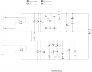
Let's take this cap multiplier for instance.

It is obvious to me that C1 and C2 are seeing the full rail. Maybe even C3? although it does run through a resistor.
C4 connects to the base of a transistor....does this determine anything?
And finally C10 output cap. I know from this circuit that it has up to a 4v drop so this can be a little lower but I can see that it is over the rails so I can determine that.
I don't think I'm wording this very well but you probably get my drift. Maybe I should have used an amp schematic as an example.
Long question short. Are you experienced guys able to look at a schematic and know that some caps can be lower voltage?!
Thanks
My knowledge in this amazing hobby is growing but obviously every day is a school day.
Without simming is there a rule of thumb when looking st schematics which capacitors see full rail voltage?
Let's take this cap multiplier for instance.
It is obvious to me that C1 and C2 are seeing the full rail. Maybe even C3? although it does run through a resistor.
C4 connects to the base of a transistor....does this determine anything?
And finally C10 output cap. I know from this circuit that it has up to a 4v drop so this can be a little lower but I can see that it is over the rails so I can determine that.
I don't think I'm wording this very well but you probably get my drift. Maybe I should have used an amp schematic as an example.
Long question short. Are you experienced guys able to look at a schematic and know that some caps can be lower voltage?!
Thanks
Your image doesn't open at all for me.
Like this:
How to attach images to your posts.
In most cases yes 🙂
Like this:
How to attach images to your posts.
Long question short. Are you experienced guys able to look at a schematic and know that some caps can be lower voltage?!
In most cases yes 🙂
I've attached dozens of images and no problems. Its there for me. It is actually a downloaded image off the forum.!
Th
Th
Dear jimk04,
Capacitor C10 alone experiences a worst case potential equal to the output voltage whereas all others see full input voltage across them. However, it's always a good practice to maintain some safety margin above the worst-case voltage, in order to ensure long-term reliability.
All the best.
Capacitor C10 alone experiences a worst case potential equal to the output voltage whereas all others see full input voltage across them. However, it's always a good practice to maintain some safety margin above the worst-case voltage, in order to ensure long-term reliability.
All the best.
C1, C2 (and C3 for this purpose) all see the full DC input voltage. This will equal the transformer voltage (its rms value) multiplied by 1.4
You should add a safety margin of say at least 30% to whatever voltage that calculates out as.
C4 (and C10) see the same value as the voltage on the preset wiper, whatever that may be.
These caps should also be scaled appropriately and you should also consider whether you want protection from a failure of the regulator or not.
As drawn the range of output voltage adjustment is very limited and so selecting a voltage rating equal to C1, C2 and C3 would make sense.
Same methodology applies to the negative rail section.
Thanks for the replies. This a a cap mx board and the voltage adjustment is to control the ripple reduction so is only from 2 to 4v drop i believe. So yes a small window of adjustment.
I think I recall seeing somewhere, maybe a power amp thread, where some of the electrolytic could be 16v, whereas the input rails and so on were 63v....assuming 50v DC power supply. I wondered where these lower voltage caps would be in the schematic and how I would ascertain they could be lower voltage.
I know I am rambling to please ignore this thread if it is annoying.
*What you show* , for all practical means *all* caps must stand raw rail voltage (+20% or more for safety).
You are NOT reducing from 63V to 16V or some similar HUGE difference but from "+V" to "+V-5V" or so.
Pot *can* be set to Max where the voltage divider becomes 150 ohm > 11K
Count that as "nothing" as far as voltage reduction goes.
You are NOT reducing from 63V to 16V or some similar HUGE difference but from "+V" to "+V-5V" or so.
Pot *can* be set to Max where the voltage divider becomes 150 ohm > 11K
Count that as "nothing" as far as voltage reduction goes.
A lower rating than rail voltage rating could be for a cathode/emitter/source
resistor bypass capacitor, or for input signal coupling. A cascading failure
could in some cases, apply excessive DC voltage to such capacitors.
To determine the voltage ratings, short all the L, and remove all the C.
Use Ohm's law to establish all the node DC voltages in the circuit.
Subtract the DC voltages present at the ends of each capacitor to get the
quiescent DC voltage across it. If one end has +30VDC, and the other end
has -10VDC, then there is +40VDC across it. Increase the calculated voltage
ratings by 20% to 50% for longer life and reliability.
A bipolar type is needed if the signal causes both polarities to be seen by the capacitor.
Sometimes start-up transients will require a higher voltage rating than would otherwise be needed.
Last edited:
Thanks for the replies. This a a cap mx board and the voltage adjustment is to control the ripple reduction so is only from 2 to 4v drop i believe. So yes a small window of adjustment.
I think I recall seeing somewhere, maybe a power amp thread, where some of the electrolytic could be 16v, whereas the input rails and so on were 63v....assuming 50v DC power supply. I wondered where these lower voltage caps would be in the schematic and how I would ascertain they could be lower voltage.
I know I am rambling to please ignore this thread if it is annoying.
Many caps in all kinds of equipment never see the full rail voltage, it all depends on how the circuit is configured. For example a capacitor on the output of a 12v regulator that is in turn fed from a 35 volt rail will never see more than 12 volts. We would choose a 16v cap here. If the regulator failed then the cap could see more voltage (up to 35 volts) but the risk of that is low and a manufacturer or designer would not in that situation specify a higher voltage cap.
An input coupling cap or output coupling cap on an opamp stage would normally see essentially zero volts DC at all times even though the supply might be as high as -/+22 volts (or even more). A low voltage cap like a 6.3v one might be used here.
A speaker coupling cap on an AC coupled amplifier (like the ACA amp) should only ever see half the supply voltage as the output point is biased to one half rail voltage. So for the ACA running on 24 volts DC a 12 volt cap should be OK but here we would never do that and such a cap would be specced to withstand the full rail voltage in case an amp failure ever occurred.
Thanks for all replies.
@JmFahey. The schematic i show is unrelated to my theoretical power amp 63v/16v scenario but I appreciate the time for tour reply.
@rayma. Your first paragraph is very interesting. I need to learn what these 'systems' look like on a schema
@Mooly...your 2nd and 3rs paragraphs are fairly golden . Thanks i understand the dual rail thing negating any offset
@Simon....Nice one! I was hoping to understand this at a schematic level before I populate and power up.! Hole you are well BTW.
As I hope you all are. And agsin thanksto all for attempting to help this electronics infant! I know it can get frustrating trying to lead the blind.
- Home
- Amplifiers
- Power Supplies
- Is there a way to determine which caps see full rail voltage?