Sanyo RD 4260

This cassette deck was working with no problems but has very recently developed a very high pitched whine and the two meters go off the scale when playing any tape. The sound via a Cambridge Audio amplifier is very muffled.

I've repaired/restored many valve radios, transistor sets, turntables and various bits of hi-fi but this make and model is new to me?

Anyone recognise these symptoms and give me a heads up on where to start looking for the source of the problem?

Loopback and ffmpeg

I'm trying to use the Loopback device to stream audio from a browser into my asound file.
As a starting point I've installed the snd-aloop module and can see Loopback as an audio device, and installed ffmpeg.
Running aplay -l gives me:
card 0: Device [USB Advanced Audio Device]
card 1: Loopback [Loopback]
To get grips with it all, I've run:
ffmpeg -f alsa -i hw:1,0 -f alsa hw:0,0
selected Loopback in the volume control, and set the browser streaming audio.
Looking at /proc/asound the two cards are shown as running, but no sound comes from the headphones plugged into the USB widget.

In Volume ontrol , Device Profiles there is a long list of options, and clicking on the ones that look promising makes no difference. A screenshot of ffmpeg running is attached (couldn't copy the text)

Selecting the USB device plays sound through the headphones.

This is all on a Raspberry Pi 5.

Anyone care to offer a way of making this work? My aging brain is filling up rapidly!

TIA. Andy

Attachments

  • 20250219_17h29m50s_grim.png
    20250219_17h29m50s_grim.png
    108.3 KB · Views: 54

switching device for measurements

hello everyone. lately i've been doing a lot of impedance measurements with a 100 ohm resistor in series with the speaker connected to the headphone output of my e-mu sound card. sometimes i have to switch to SPL measurement and therefore i have to change the connections. i would like to use a box that allows you to change the type of measurement with a simple switch. i could build a box like this by buying all the components online and then proceed with the assembly but i would like to know if there is a ready-to-use box that doesn't have an excessively higher price than the diy self-construction. hello and thanks.

CD104 question

I picked up a Magnavox FD1040 (Philips CD104) last week that was not working at all -- would power on but would not spin or read the TOC. I replaced the axial electrolytic caps and repaired the griplets on the servo and decoder board. Now, it spins and reads the TOC. However, after that read, the turntable continues spinning. Pressing Stop causes the turntable to stop spinning. The player will then play tracks fine from start to finish without incident. This symptom happens every time.

Clearly then, the turntable motor circuit is fine or the stop button would not work at all and the unit would not play the entire disk.

I am trying to understand where the instruction comes from that tells the TT motor to stop after the initial TOC read. Has anyone seen this problem before? And can anyone explain the sequencing that sends the stop signal to the motor during this process?

Noise

Hello everyone,
This is a non audio project strictly power.
The project : autonomously control a slot car. HO scale 1/64 to be exact.
I have a 5-30v 0-5a adjustable dc to dc pwm converter (it came from temu so spec's are Shecky at best ). I hacked the MOSFET circuit of the pwm controller and I am controlling it with an arduino to control the speed of the car. The arduino uses a signal from IR sensors to change the speed of the motor. All components and modules are grounded to the same plain. IR sensors work great right up until you put the car in the circuit . With my very limited knowledge of electronics and an old Tektronix 2215 Oscope that i barely know how to use . I think I've verified that the Noise is coming from the motor back through the pwm controller, which makes me think I need a capacitator, filter or inductor ? on the output side of the speed controller. Any thoughts or ideas would be greatly apricated.

Thanks
Kirk

New member from a sunny island

Hello good people. I am from a tiny, sunny island, Singapore. We are often seen as a red dot in the asia-pacific region.

I have joined this forum with hope to learn something about circuitry. I am not from an electrical engineering background. It is quite frustrating for me to see people fixing these electrical equipment and getting them working when all I can do it watch in envy. I have so much respect for those who fiddle with these equipment, getting them working when all hope is lost(when the manufacturer tells you to pack the unit up and leave it aside as a paperweight). I have asked some of these skilled tradesmen how they acquired this level of expertise and they always tell me it was honed through years of fiddling with faulty equipment or just about anything electrical they get their hands on. I guess I have to start somewhere. My aim would be to know the fundamentals about how these things work and basic troubleshooting if a fault comes up.

On a sidenote, I have been introduced to music from a young age and have been fortunate to be handed over a decent stereo set comprising a set of speakers, receiver, power amp and a cd player. At this current moment, I am trying to get all these equipment serviced for operation. Recently, I had to face some major setbacks with the power amp acting up. It is the NAD 208 THX. Yes, you heard it right. It is the beast from the 90s with a list of problems. I love this amp so much that I wanted to build my hi-fi setup around it. Those whom I have spoken with held this amp in high regard. I have been advised by many across the globe that ths amp is a keeper when fixed. It was reassuring and encouraging to hear that I have a piece that is well worth the fix. It was well cared for but no amount of care can mitigate internal wear and tear. I will post my concerns on the solid state thread. Perhaps the esteemed members here can help me out or at least point me the right way forward. Thank you for allowing me to be part of this community.

Group Buy for Jan's high voltage regulator

Group Buy for Jan's high voltage regulator - update for higher voltage

As suggested in my thread about my high voltage regulator for tube amps, this is the Group Buy thread for it.

I am offering the following half-kit:

- PCB;
- Current source LT3092 SMD soldered to the board;
- overload reset switch SMD soldered to the board;
- Pass device FDP12N60NZ;
- low current high brightness LED;
- depletion mode HV MOSFET IXTP08N100D2.

Everything else is easy to find and/or already in your parts box.

All info for building can be found here: T-reg HV regulator | Linear Audio NL

Update Feb. 2021: T-reg is now available in the diyaudio store!

Jan

Original QUAD ESL wood (or not)

There is talk about spider legs and stack constructions for the original Quad ESL, but little talk about the original feet.
Some make something that looks a bit like the original feet which are often lots or bad or damaged etc.
I took the 100% original design and 3D printed the feet, re-inforced it with a 6 mm aluminium rod for strength.
PLA is available in various wood resembling colours and the mounting plate is black like the originals.

set voetjes.jpg
  • Like
Reactions: Zvon and ejp

A great power reducing headphone adapter for vintage power amps

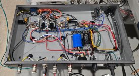
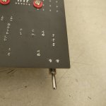
I have been restoring vintage amplifiers from consoles and 8-track players, and turning them into stand-alone components. These old chassis don't have headphone outputs. I have no intention of modifying them to install this output, but I do want the ability to listen to them post-restoration and evaluate more accurately the sound quality with headphones. I can hear more detail that way, and in general the differences in sound quality between amplifiers can be subtle.

I ran across a great design from Rod Elliott's ESP website, 
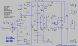
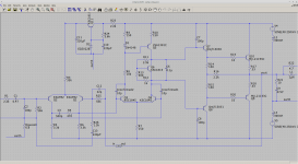
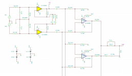
project 100, "Headphone Adapters for Power Amplifiers" that provides a simple design that safely reduces the output power to a safe level. The schematic below (for version 1) is accompanied by a table of optimal values of R1 and R3 for the nominal output power rating of the amplifier, to provide a headphone output limited to 5Vrms and a 120Ω output impedance. He also offers a version 2 with a ~2Ω output impedance, but it requires much higher wattage (10-40W) resistors which are more expensive and require more cooling consideration. (If you want to debate about whether 120Ω output impedance should be used with modern headphones, I'll put my opinion on this at the bottom to minimize distraction here)
p100-f1.gif


The adapter circuit provides a light loading to the amplifier of several hundred ohms, which most if not all amplifiers will tolerate well (yes, even most reasonably tuned tube amps). The voltage divider reduces the output amplitude, and R3 tunes the output impedance. Note that this adapter can only be used with ground referenced outputs (most are), and absolutely not with BTL (Bridge Tied Load) amplifiers as the negative side of Left and Right are shorted together at the headphone socket. Actual output volume of the headphones driven by this circuit depends upon their impedance. My favorite phones are 32Ω and 50Ω and this circuit provides adequate volume for these, which are considered harder to drive adequately.

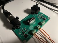
I eliminated the DPDT switch, as my assembly was to be used as a temporary test adapter, connected instead of the speakers. The accompanying table on Rod's page provides values for 10W to 250W power amplifiers, with the recommendation to use the values for a higher wattage amp if you want less output to your phones and vice versa. He gives power ratings for R1, but not R2=120Ω. I would recommend a 1W at least for that. R3 can be rather small, I used 1/2W for that.

Most of the amplifiers I rebuild are 25W per channel or less, but I used the value for 40W (R1=330Ω, R3=33Ω) as I really don't need much power.

Headphone_Adapter_Resistor_Table.gif


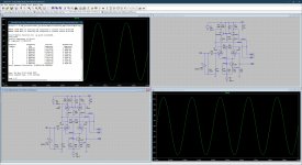
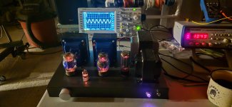
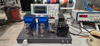
I tacked together a temporary test version to make sure I was happy with the output level across several amplifiers. For high wattage amplifiers, you simply use it with the volume at lower levels. Given I selected values for a 40W output, I found that with a 12W and even a flea power 4W amp I was still able to achieve robust volume out of my 32Ω phones, but had to turn the volume nearly all the way up. Given that I was tempted to drop down to the 20W values, but I may want to use this with 50W and 100W amps and still have some volume control, so I think this is a good tradeoff.

OK - My take on the hotly debated 120Ω source impedance for headphones question. Most consumer amplifiers typically have just a series resistor between the output and the headphone jack. I have seen anywhere from 100Ω to 500Ω, typically higher resistances for higher output wattage. This was a cheap and dirty way to limit the available power so you were less likely blow up your phones, heard less noise, and could listen at some reasonable low output for a low volume setting. Since headphone impedances are all over the place, standardizing on 120Ω was the best one-size-fits-all compromise. I think this is where the 120Ω standard came from (to ensure basic compatibility) more than some exacting audiophile concern about driver damping factor. Obviously voltage amplitude is lost across the 120Ω, so to use it you have to drive a higher voltage amplitude out of the headphone amp. This is very difficult for todays portable low voltage battery powered headphone outputs, most of which are very low power output op-amp drivers. There is not enough output power to worry about limiting damage, so modern equipment skips the 120Ω output impedance and typically has very low (single digit Ω) output impedance. However, whether headphone manufacturers have actually changed their designs to work "optimally" with this is questionable. Unless they are high end headphones that explicitly state the optimal impedance, it probably was not even a consideration.

Obviously, you will have a lower damping factor for 120Ω, resulting in a fatter, less controlled or warmer/softer bass. For ~0Ω output with a higher damping factor, you should have tighter, more controlled, accurate bass. This is obviously more important for speakers, which have much higher moving mass and momentum than a headphone diaphram. Whether the different damping factor will be audible, and which sounds better to you with your particular headphones, however, will require experimentation. Personally, I have found very little difference at least to my ears between the two impedances.

Simple Class A mosFET amplifier

I saw a simple amplifier but thought maybe I can do it better without to many components.
Here is the result. Its not very temperature stable but in class A it gets less hot the louder you play.
So it is just to measure the current in the output transistors = voltage over R8 or R9 and adjust it with P1 to
a little more than Feed voltage / 4 * R speaker. But take half an Hour for the heat to be stable after the last adjustment.
It is easily adapted to other voltages and speaker impedances. Distortion is about 0,1% which maybe some people don't hear.
Noise is extremely low under 5 uv 20 - 20k. Common mode rejection is determined by C2. Frequency response is good 25 Hz to 95kHz -3dB.
View attachment 1418335

But looking at the results it is possible to do it much better. Faster and much lower distortion but a little more noise.
The problem now is that the P1 is very sensitive in adjusting the current.
Now the anti thump + radio interference filter on the input is included. But still pretty simple.
I changed the R12 to 0,82 ohm because I believe the IRF 540 has about 5S at about 1A.

View attachment 1418382
  • Like
Reactions: lineup

Looking for cheap 3d printed MEH

Hello everyone,
I tried to read what I can, but I don't understand hornresp at all. I can do work in ATH, VituixCAD,WinISD and Fusion.
I'm looking for a project/files to 3d print horn that is not bigger than 600mmx600mm. Cheap drivers and polar plots see would be a bonus point. Where I live I don't think anybody have build MEH so I have never heard it. Please help me if you can 🙂
Ultimately I can do some wood work and also I have dipole subs (form LX521).

Any love for TDA1541 chips?

Just checking to see if anyone wants 4x TDA1541 chips for free? They are currently stiiting in a Cambridge Audio CD2, ashamed to say I skipped one of these players already and this was a working player too but I got messed up a little and let it rust away for years. I am skipping this one today but i can pull the DAC pcb bit if anyone is still experimenting with this thing. I was obsessed for years.....

Alan
  • Like
Reactions: Gill.T

Hello from Canberra, Australia

After more than 30 years, I am finally building speakers again! I've been exploring full-range speakers and have recently built an FH3 with Alpair 7.3, and also a box similar to the Sibelius. I am keen to learn more about these drivers and designs, having recently discovered the threads in this forum, and contribute my experiences where relevant.
  • Like
Reactions: audiosteve

China CFA found at Pinterest site

Hi guys,

The other week while wasting time on a lazy afternoon, I was inattentively doing a random search of a CFA amp schematic online. One schematic of which looks like of chinese origin at Pinterest site caught my interest. I took a quick screenshot on some parts of it (Pinterest won't let me see the whole schematic without registering). I tried to recreate it in LTSpice, with some changes in order to make it work accordingly (specifically IRFs for the outputs). It was surprising that the circuit displays a very good voltage/current balance, low THD and has a good gain and phase margin. The only drawback for me was that it is inherently H3 dominant hence I used low gain transistors (high gain transistors significantly boosts H3).
Fueled by a 'want to build one CFA', I modified the circuit in order to meet my preferences . Make it H2 dominant low THD and still showing good balance of currents and voltages. I humbly ask the more knowledgeable ones to check on my work if my circuit will actually work right when built in a real hardware. LTSpice simulation say's it will (sim files attached). This is my first CFA amp build if everything goes according to plan and the last build of my DIY Audio hobby.
Any thoughts folks?

Thank you!
Albert

Attachments

  • China_CFA.png
    China_CFA.png
    118.7 KB · Views: 246
  • CFA_Myversion.png
    CFA_Myversion.png
    117.2 KB · Views: 240
  • Screenshot_2025-01-24-21-04-03-195_com.android.chrome.jpg
    Screenshot_2025-01-24-21-04-03-195_com.android.chrome.jpg
    131.5 KB · Views: 192
  • Screenshot_2025-01-24-21-04-45-105_com.android.chrome.jpg
    Screenshot_2025-01-24-21-04-45-105_com.android.chrome.jpg
    134.3 KB · Views: 228
  • CFA_China.zip
    CFA_China.zip
    16.4 KB · Views: 42

Midrange problem with 3-way Acoustic 807 cabs

I've been working with a pair of vintage Acoustic 807 cabs and I've run into an issue. When I bought them, one of the Heppner 4"x10" midrange horns was nonfunctional and efforts to replace its diaphragm/voice coil assembly were unsuccessful. There have been only two models of new-production integrated 4"x10" horn loudspeakers available in the United States (regardless of how they're branded - brands include Peavey and Pyle) and I have bought a pair of each to try as replacements. I wound up using the metal-horn model. In order to get the behavior of the two cabs close to the same (the crossover connections are undocumented and there was no telling which way of connecting them was what Acoustic intended), I bought two Dayton Audio units with crossover points at 500 and 4000Hz and installed one. As a casual test, I was blowing sine waves through the cab and when I had the frequency set to 1000Hz - which the crossover should be sending predominantly to the midrange horn - and I made a disturbing discovery. Above a certain amplitude - still a very low power level - I could hear a set of harmonics start up and I confirmed what I was hearing with a measurement mic and the REW app. The appearance of upper harmonics wasn't gradual; turn up the gain when they aren't there and at a certain threshold they switch on. When I swapped the horn out with the one from the other cab the threshold wasn't there - that is, until I grabbed the back end of the horn and wrenched it around with my bare hands. Then I tried the other pair of horns that I'd bought - same thing. Then I tried the cabs' surviving original Heppner horn - same thing.

I am left to conclude that horns of this sort are hot garbage. Lest you think it was something other than the horns themselves, I tested out all five of the horns I had on hand with the power amp connected directly to them, and I didn't get the harmonics when connecting the power amp to a JBL L56 cabinet or cheap piezo tweeters (albeit at like 5000-8000Hz). If these horns are acting like kazoos with a sinewave signal, they've got to be making absolute hash out of program and I can't abide it.

In looking for combinations of individual compression drivers and horn lenses, I've been unable to find anything that's suitable yet will also fit into the cabs' recessed mounting place, so I've decided to just screw a blank panel over the hole and set a horn/driver combination atop the cab, either bare (Voice-Of-The-Theater-style) or in separate enclosures that will rest atop the 807 cabs. This frees me up to use any of a pretty wide range of horn lenses, and I've identified a driver that seems workable in terms of power handling and frequency range (this one is rated 75W RMS and 400-8000Hz). So here is my question: given that the original horn was 4"x10" and recessed into a slot with panels to either side that sit diagonally in plan, front to back (thereby kinda-sorta extending the horizontal horn profile to nearly the width of the cab), what do you think it would do to use a horn lens the size of, say, 5-1/8" x 15-3/16" instead? The only thing I'm worried about is that if the dispersion is much wider or narrower than that of the splayed piezo tweeters mounted underneath that slot or the two vertically-arranged 12" speakers, then the off-axis performance might be mid-high or mid-low. BTW, mostly these cabs will be used for playing keyboards through at significant volumes, widely spaced, and set well back from the audience so getting even dispersion between woofers, mid, and tweeters is meaningful.

Hypothetical open labyrinth cabinet, I need feedback

I moved from box speakers to open baffle a while ago and the hardest part still seems the fact that due to cancellation the low bass is a challenge and either requires very large baffles and/or very large displacement.

As a way to accommodate large baffles they are often folded (open box, H frame, Ripole) But this creates enclosed air spaces and parallel walls that create unwanted resonances.

One supposed way to deal with this is the Hartley "boffle" enclosure, something I want to test for myself in the near future.

But last night I got another idea that seems crazy..... I need someone with enough physics knowledge to tell me why this is a dumb idea......otherwise I have to try this as well.

Wat if you fastened a strong steel mesh to the back of an open back cabinet (and around the driver) and filled the cabinet with pebbles, marbles or gravel?

This would somewhat restrict the air flow....a bit like slot loading maybe?

There would be some resistance.....a bit like a aperiodic vent?

The path length from front to back would be larger?

The weight would kill all cabinet vibrations

Would it kill air column and/or quarter wave resonances?

Would it be worth trying? Or has it been done already?

Another variation would be to add some polyfill in between the stones/marbles

Improving a Parasound HCA-800 II to -100dB THD

There's a beater Parasound HCA-800 II on the bench. It's just quit smoking and is ready for a new start.

I'd thought this IPS and VAS design was a "dead end": it'd be nice to improve its performance beyond the ~75dB it's good for, but there's no easy way to add a current mirror or VAS buffer or cascode that would help things. But there's hope for it yet!

Here's my capture of the factory schematic -- which includes some component values recovered from the unit where the schematic left us to guess. (Sorry, component names here don't match the oem schematic. My bad.)

Attachments

  • para_oem.png
    para_oem.png
    53.4 KB · Views: 529

For Sale PCBs I have laying around

I have the following pcb's laying around that I would like to offer. Let me know if you can use them:

Top row: Project16 / Prasi CRC psu boards: $10usd for pair / 3 pairs available.

Mid Row: Xrk audio / JPS64 CapMx boards good for 1 amp, so suitable for Dac, preamp etc, not high power amp: $10usd for pair

Btm Row: Analog Design / Prasi LT4320 active bridge rectifier / controller, suitable for offboard attachment on a CRCRC psu or any CRC that you have access to +/- DC points. See attached pic or post#238 on the GB:CRCRC thread for attaching the controlling board. $10usd for 4 boards.

Attachments

  • Sales pcbs.jpg
    Sales pcbs.jpg
    407.1 KB · Views: 105
  • 123QWERTY.png
    123QWERTY.png
    213 KB · Views: 106

Another LM3886 in parallel attempt - this time 4 of them!

Hello all,

Excited about my latest revision of the LM3886-based amplifier!

Initially, I was thinking of putting two of them in parallel, but then it was three, and later on, it became four lol. The reason is that I want to bridge two channels and thus quadruple the power to 200W (or 400W into 4R).

So far, using a 25V-0-25V transformer, I was able to get 100W into a 4R load with very low THD+N of 0.00142% @ 1kHz. THD is even lower at 0.00135%.

The 8R load showed even more impressive results of 50W at 0.00047% THD or 0.00066% THD+N.

10kHz measurements are also attached.

It is argued that the most realistic test for the amplifier is running a 1kHz tone into a 4R load at 5W of output. Such a test is attached too and results in 0.00085% THD or 0.00105% THD+N.

One of the goals for this build was to achieve very low distortion, especially at frequencies higher than 1kHz. Many commercial amplifiers optimize for 1kHz performance, as this is usually what is being measured by the reviewers. With my build, I wanted to optimize for great performance across all frequencies.

Granted, mine is more of a brute force approach to reduce distortion by adding more chips in parallel. I recognize that at some point, such an approach will hit a point of diminishing returns where by adding more chips the distortion will not be reduced.

Listening tests will follow.

Edit:

Listening Tests

I'm delighted to report that I've confirmed exceptional measurement results through three days of listening to the amplifier.

What's especially noteworthy is the level of resolution—I’m picking up nuances in the music that were previously less apparent. Clarity is another standout feature, with soft yet distinct high frequencies and excellent resolution and spaciousness in the midrange.

The low end leans towards the softer side. Compared to the Modulus-86, the low end is gentler and less pronounced, whereas the Modulus-86 amp has a punchier low end.

Edit:

Attached is schematics in Tina-TI to illustrate the idea behind the amp. Input unity buffers are implemented using OPA1656, as they are capable of providing sufficient current drive for the LM3886s. This results in much cleaner highs, pleasing mids, and a "black" background.

Attachments

  • 100W_1khz_4R.PNG
    100W_1khz_4R.PNG
    37.1 KB · Views: 438
  • 1khz_53w_zeroed_graph_8R.PNG
    1khz_53w_zeroed_graph_8R.PNG
    39.4 KB · Views: 274
  • 100W_10khz.PNG
    100W_10khz.PNG
    36.5 KB · Views: 250
  • 10khz_53w_zeroed_graph.PNG
    10khz_53w_zeroed_graph.PNG
    36.7 KB · Views: 241
  • 5W_1khz____scaled___4R.PNG
    5W_1khz____scaled___4R.PNG
    38.6 KB · Views: 343
  • IMG_2798.jpeg
    IMG_2798.jpeg
    284.5 KB · Views: 375
  • IMG_2799.jpeg
    IMG_2799.jpeg
    368.2 KB · Views: 358
  • IMG_2800.jpeg
    IMG_2800.jpeg
    376.5 KB · Views: 447
  • IMG_3226.png
    IMG_3226.png
    17.8 KB · Views: 305

Need help for speaker magnet magnetizer

My application is a capacitive discharge type design. 800vdc.
I am currently using a mechanical switch for initial testing. I charge small 120mm magnets.
I now want to use thyristor for switch.
I googled a lot but i did not get anything that can clearly explain how to use the circuit. How much gate supply should be used and how much gate charge must be used.
I saw many people using KP1500 thyristor for their magnetizer. But never asked them the application circuit.
Any help would be highly appreciated.
Also brothers no theoretical knowledge available here so please explain in very basic english. 😊😊

Class D Type 4 very high distortion issue

Hi,

I’m working on a clone BASSFACE class D Type 4 amplifier that was brought in with a burnt-out power supply and a dead output section.

It’s using 10 IRF260Ns for its output.

After fixing the power supply, I noticed the drive waveform on the output had a step on the turn-on, and the low-side FETs were running hot without a load at idle.

I changed the driver transistors from 2316, 916 to 2073, 940 respectively, and doing so solved the problem with the drive waveform. However, the amplifier was getting distortion well before the clipping point. The driver transistors on the low side, especially the 2073, were also running hot when I did this. I switched back to the original drivers to see if the distortion was also present with them fitted, and indeed it was, and it was much worse.

I also tried leaving the 2073, 940 on the high side and the original transistors on the low side, which was somewhat better. I also tried other transistors like 649, 669, and the results were much worse.

Any idea on what is causing this and how I can fix it?

Any help would be greatly appreciated. (I’m kind of new to fixing class D amps 😅)

Also, the rail voltage is 180 peak-to-peak.
IMG_20240923_224207-01.jpeg

IMG_20240923_224420-01.jpeg

Basic hi end Pi streamer - BOM

I know.. lots and lots of info on building a steamer from RaspberryPi and this is not a new thread by any means. However I am looking to build a Pi based streamer with best parts and power supplies and put it all in a nice chassis and the add on options to the Pi are where I’m getting lost.

Goal is to output digital via USB or Coax Spdif to an external DAC (Pontus ii from denafrips) then my preamp and then my amp. Today I’m using a blue node 2 with an upgraded external linear power supply. Sounds good to me but I just started using Roon and need a new project.

Looking at the IanCanada stuff and wondering if the following setup is what I need…

  • RaspPi 4 running ropieee
  • something that takes digital stream from Pi on the GPIOs and sends using I2S to another board
  • is this other board a “reclocker” which is a better digital out than anything the Pi would do natively? Assuming so I would upgrade this with premium clocks
  • use the clockers digital out on coax or usb to my external dac
  • need a linear power supply with beefy transformers to provide power to Pi and clocker. Do I need separate power supplies for Pi vs. reclocker?

Is above sufficient or do I need anything else in this chain? My sources are easy - I stream tidal only and no local files. Do I have to worry about drivers or is there a better setup if sound quality is my goal here? Welcome guidance as this will be my first DIY audio component build.

Vacuum tube diode destructive test

Everyone says that TV damper diodes can take a heavy beating. I want to find out how realistic the maximum current data are when used for HV rectification. I have a few EY80s I'm willing to sacrifice. Datasheet says max current 180 mA AND 'peak' current 400 mA. That's for their intended use in TVs, but how does that translate to rectification duties?
Main question: what will happen when they fail? Red (orange, yellow) plating I guess, and then? They just stop working? Or a short between anode and cathode?

UAC2.0 on STM32

Hello! I am trying to make USB Audio class 2 device based on STM32 MCU.
Hardware: a board with STM32F722 and external USB HS PHY.
Software: USB Audio class 1 example from ST as a base. I changed USB desctriptor and add code for new entites requests and made board work in HS mode. But in device manager in Windows the device appears with exclamation mark. USB Descriptor analyzer shows no errors. USB traffic analyzer shows no errors. But after some actions on the bus - IOCTL_USB_GET_DEVICE_CHARACTERISTICS (ioctl 0x00220480) 134, 135 positions in log - the device gets "Surprise Removal". Investigating MCU software by means of debugger ended up without any certain results: application is running, no faults detected.
I am confused by this situation and do not know what further steps I should take to get the device enumerated properly. Any help would be much appriciated.
UAC2.0_surprise_removal.jpg

Elliott Sound Products (ESP) website

Firstly, I'd like to thank the countless DIY people worldwide who have supported my (previous) site over the last 15 years.

While it may appear that my site is gone, it's just been moved to Elliott Sound Products - The Audio Pages (Main Index)

The rumours of my death (or at least that of my website) have been greatly exaggerated 😀

I could go into some detail about the shoddy way I was treated by my hosting provider, but I shall refrain. Suffice to say that it's still alive, and hopefully it will get well again soon.

The US Hosting 'service' has struck again, and this time I'm abandoning it completely. My Australian hosted site is also HTTPS, so that gives it a bit of security that Westhost claimed wasn't possible.

18 years is a very long time for any website, and it's distressing when its URL is changed. Some may recall that the same thing happened to my Australian website (and my primary email address) recently, so it's been a double-whammy. (that's now a triple-whammy with the last notification). The old (whsites.net) site will close completely sometime before June 2020. I'm in the process of setting up re-directs for all the pages, something of a chore since there are so many.

Please feel free to visit the site at its new home - Elliott Sound Products - The Audio Pages (Main Index)

Cheers, Rod Elliott

For Sale 2 x AD1862-N including varoius Miro dac board's and PSU's

I'm going in a different direction now so have for sale,

2 x AD1862-N dac chips NOS

2 x Miro 1862 dac boards

1 x pcm56p dac board

1 x pcm58p board

1 x tda1541a psu board

2 x Vunces dac iv stage boards

2 x miro psu board

1 x spidif / optical to is2 board including crystal

£70 plus postage to wherever you are in the world.

I'm sure that I bought the shift registers for the 1862 dacs if I can find them I'll include them.
20250218_152912.jpg
20250218_153621.jpg
20250218_153635.jpg
20250218_153640.jpg
20250218_153644.jpg
20250218_153647.jpg
20250218_153651.jpg
20250218_153704.jpg
20250218_153708.jpg
20250218_153712.jpg

Hello from Switzerland, land of cheese and Goldmund, Soulution, Nagra...

Hello everyone,
I love vintage hifi and spend a lot of time listening to vocal jazz.
When I was about 20, I used to drool over the windows of the most famous audio stores. Now I can enjoy myself and I've had the system of my dreams for about fifteen years.
I'm amazed by the positive spirit and mutual support I've found on this forum.
Thank you for accepting me.

MAX4466 Electret Microphone Pre-amplifier Module + SSM2167 Voice Compression

Anyone use one of these? I have two in hand. Bet you could get it to work with a dynamic mic as well - just accommodate the electret bias current, cap decouple to the Vcc/2 signal midpoint. Specs on the IC parts seem impressive for the $10 decade of expenditure. Ok, it's not a $35k Fairchild 660, but maybe with some I/O transformers? One would think you could build it right into the mic and have a vocal mic that "just does it".

1739997621537.png

Attachments

  • Like
Reactions: djgibson51

Finding the right listening position

Hey everyone, my first post here. I´ve just moved in a new mixing room and are currently trying to find the best listening position. I attach a sketch of the room, which has already a lot of absorption installed. I use the Yamaha HS7 in my setup and placing them as close to the front wall as possible to get the most bass out of it and to remove almost all front wall SBIR. I already made some measurements using REW, where in each measurement the monitor is moved around 20 cm inwards from the side wall but keeping the short front wall distance. Blue (1st measurement), Orange 2nd, Green 3rd, Purple 4th.
What do you think? Thanks!

Bildschirmfoto 2025-02-17 um 09.41.45.png
118.jpg
128.jpg
148.jpg
168.jpg

Sand in speaker to damp resonance?

I have a pair of Vienna Acoustics speakers, that have a sealed chamber in the bottom to fill with sand. I recall (20+ years ago now, tho) that I noted it helped deepen the bass on the speakers, I assume by damping panel resonance. It is not a giant speaker tho, only 8"Wx10"Dx34"H, with 1" HDF walls.

Has anyone tried sand in a similar capacity? Does it really do anything?

I am building a new speaker, using 11-ply 3/4" baltic birch ply for the front, back, and internal supports. The sides will be curved, and I am using 3 layers of overlapping 3/8" birch wiggle wood (fun stuff!) for a 1 1/8" total side width.

I am wondering if I should build in a similar sand compartment in the new speakers. I haven't seen any other designs leverage this, so perhaps is it only a small effect?

2 x 10 inch driver selection for dual opposed subwoofer

Hi there,

This will be my first attempt at building custom subwoofer and I do have 0 experience in building sub.
It will be used in a room of size ~25sq m, at small or medium listening levels. No block parties.

Would like to go for dual opposed drivers, as I do not like any external vibrations and I somehow think that 2 x 10 inch drivers will be more than enough for my needs.
Amp will be external or Hypex FA251, would like not to go for the most expensive in the lineup. In any case I will have full DSP control, external or Hypex.

Priority is a sealed one, but the woodworking is not a problem, can do the prototypes of any type: sealed, BR, slot or any other, and probably try more than one type before building final enclosure.

The approximate requirements:
-2 x 10 inch class subwoofer drivers, probably I need 2 x 2Ω or 2 x 8Ω to have final impedance of 4Ω or some other DVC combo. Affordable and available in EU, cast aluminum or plastic basket, no stamped steel - that is the only "hard" requirement.
-1 x 250W (4Ω) is a target power for both drivers, would like not to go for more.
-Reasonable all-around good driver, good price/performance ratio, probably more from home use/hifi use, no car or PA, if possible.

That is pretty much it.

Right now the go-to drivers for me are SB29SWNRX-S75-6, but they are little on the expensive side for 190EUR/driver, and have no idea if it will work with Hypex when connected in parallel on 3Ω load.
Another options:
105EUR Redcatt (BPA custom brand?) 101FHW- available in 8Ω, smaller VC, incomplete TS data
90EUR Reckhorn D-250, which I don't know if it is available in 8Ω, very scarce TS data
125EUR Ciare HS251, 2x8Ω voice coils 4x8Ω total, which makes impossible to connect it for 4Ω impedance
180EUR SBA SB29NRX75-8, which is more or less the same priced woofer-subwoofer variant of the subwoofer I selected, right?

Which drivers could you recommend including outside this list?

A decent 12" neo coax at a good price?

I believe that I finally found a good 12" neo coax that doesn't cost a fortune and has the build quality of a more expensive driver.

I ordered a pair of Eminence KL3012CX8 and was pleasantly surprised when I examined then a bit closer.

One of the key things critical to a good coax that uses the cone as a horn flare is a smooth transition from the horn throat to the cone. The KL3012CX8 has a smooth radiused pole piece that provides a very even tapered transition. I dont believe this was always the case for this model driver. Reason is that I recall Erich from Diy Sound Group working with Eminence on a new coax design for his Vortex line. The machined pole piece section looks almost the same on the stock Eminence KL3012CX and the Vortex 12 driver. Its possible Eminence adopted this design feature for they're drivers as well. I tried taking a picture of the pole piece through the screened dustcap. Hopefully its visble enough.

I haven't run any tests on this driver yet, but will put it through its paces hopefully soon. It looks like it will make well with the Celestion CDX1-1745 and maybe the B&C DE250 with the right adapter. A separate adapter allows you to visually check the taper and transition inside the throat and modify it if need to. A screw on driver won't allow for this.

Attachments

  • 20221130_134630.jpg
    20221130_134630.jpg
    476.8 KB · Views: 353
  • 20221130_132940.jpg
    20221130_132940.jpg
    587.8 KB · Views: 395
  • 20221130_134411.jpg
    20221130_134411.jpg
    1,020 KB · Views: 375
  • 20221130_133149.jpg
    20221130_133149.jpg
    418.9 KB · Views: 365

PP ECL82 amp with cascode inverter

Hello everyone,
I recently looked into boxes of tubes that I collected over the years and found out to have 20 ECL82/6F3P/PCL82. Some of these look slightly used, but others are crystal clear (even NOS in boxes). I would like to build a guitar amp for a clean jazzy tone, getting around 6-7W in PP would be more than fine for me.

I would like to make a hybrid construction rather than making another clone of something common (I have already built amps in the past so I know something). I like the idea of having only 2 bottles for the whole amp. Since hybrid amps are new for me, I would like to deepen this topic and learn something new, so I decided to ask here for some pro tips 🙂
When I started thinking about the design, I came up with an idea of using hybrid cascode in the inverter, with JFETs as lower devices. Quick simulation of such a design has shown that plenty of gain is achieved (obvious) and it might work. Also found this thread:
https://www.diyaudio.com/community/threads/calling-yves.102553/
where gingertube mentioned such a configuration for ECL82.

I have a PT dedicated for ECL/PCL tubes, which has a 13V tap for PCL heaters. I can use 13V to obtain -15V for the purpose of CCS and preamp section. However, my concern is feedback, I would like to tame the gain but have no clue how to make it properly. Initial idea was to apply GNF from the OT to the "+" input of a differential opamp driving the inverter, but I am not sure this is a good way of doing it (long feedback path?). Besides, due to 0:-15V supply I would have to create artificial ground for opamps so using transistor stages might be a better idea. I was fooling around plate-to-plate feedback from output tubes to the inverter (shortest path), but could not get meaningful results in spice. I also consider using UL...

Regarding preamp, I want to have simple low/high correction and rather flat characteristics. Since cascode provides a lot of gain, the preamp section would not have to deliver a lot of amplification (at least that's how I see it). Maybe experienced users of this board could suggest something to me? Since this will be a guitar amp, the THD is not the most important matter.

Here's the schematics I've been working on.
poweramp.PNG

Cascoded 12AX7 LTP - Stupid good performance?

Alright, I've made a few posts in the last few weeks as I'm working on a new tube amplifier design and am very appreciative of all the replies and suggestions I've gotten, thanks again for that! This morning I figured that one trick I hadn't yet tried to further reduce distortion and up the gain on the input stage is to simply cascode it. Seems straightforward enough right?

Well, a mere hour or so after I made the changes in my schematic I felt I had a pretty good handle on things and ran some simulations. The results were everything I hoped for, frankly quite a bit more than that. Thinking I must've done something wrong somewhere I've double checked everything and even tossed in some transistors instead of the triodes to see whether that would give the same results and low and behold it did.

Can any of you fine gentlemen perhaps let me know whether I'm being an complete and utter idiot here, or whether I fail to understand a mechanism at play here that would yield such excellent results? But before you answer that question let me quickly give you a circuit description.

The LTP is pretty straightforward, as is the cascode, but for the additional transistor Q1 which does double duty, it acts as a constant current source and tightly controls the AC balance of the LTP which pretty much depends on how closely matched the 1Meg resistors are and no longer how well matched the two triode sections are.

Attachments

  • gimme_that_low_thd_001.jpg
    gimme_that_low_thd_001.jpg
    786.9 KB · Views: 1,272

Phono preamp schematic

I just finished building my first tube amp, the KT88 single ended amp on the Blueglow Electronics website and it sounds amazing. Now I'm looking for a companion phono preamp to go with it. I'm looking at the one in the RCA Tube Manual right now, but there must be others. Any suggestions?

Attachments

  • 20250106_200037.jpg
    20250106_200037.jpg
    540.8 KB · Views: 130
  • 20250106_194253.jpg
    20250106_194253.jpg
    280.5 KB · Views: 131
  • 20250106_194314.jpg
    20250106_194314.jpg
    415.5 KB · Views: 141

Hum from monoblocks when RCA cable is connected

Hello Masters, i need advise hopefully to resolve hum issue.
The monoblocks are Cary 805B - they're SET DHT with 6sl7 > 300B > 211.
When they turned on and connected to speakers and disconnected from a PRE - virtually zero hum comes from speakers (klipsch La Scala with 104 db sensitivity).
When RCA cables are connected from the PRE - 50hz hum appears. Not too bad - but it's there.
Hum level lower when only one monoblock is connected to the PRE. When both are connected the hum is louder.
Basic digital voltmeter (not sure if it's True RMS) shows 0.3-0.4 mv AC at speaker outputs.

Nothing connected to the PREamp.
Power cables of the PRE and the monoblocks go to the same AC strip (no filtering).
All equipment in the room is unplugged from AC.
AC receptacles + cables are USA style - so only one way is possible.

Different sets of power cables were tested.
2 sets of RCA cables were tested (all 3m/10ft length).
2 preamps were tested.

With 2 other stereo power amps i don't have this issue - both are tube push-pull, but one chassis stereo, not separate monoblocks...

What do you think?
Is there a hope?
Or having DHT with separate chassis i'm doomed for hum?

Thanks in advance !!!!

QUAD 306 revamp - I am in awe!

Folks, I want to share my journey with Quad 306, in case it might help someone else in the future. Firstly, I am in no way an electronic expert but I have been tinkering around the amplifiers for about 30 years, so I have learnt a few basics along the way.

I acquired a Quad 306 (Revision 2 PCB) from a friend. He was about to dump it in the recycling because one channel was dead and the fact that he had bought a new Marantz amp. It has since been lying around with me for a couple of years. The past month I got an itch to feel the smell of the solder again, so I opened it up to see the internals. I found a few burnt resistors and after doing some research, I replaced the resistors and turned on the amp again. I was amazed to find that's all that was wrong with the other channel, which was now working with no issues. I was also very impressed with the sound quality coming out of it. This made me think if I could improve it further.

The first step was to figure out why the resistors got burnt, but the answer was right in front of me in the Quad 306 service manual. Page 10, note (C) - "The centre-tapped DC Line is floating and some faults may cause this to shift putting up to 80v on one side possibly damaging R30/R31 (2K2ohm)." However, I also had R22 (560R) smoked out, not sure why.

So after replacing every single resistor with better-specked Vishay resistors and doing some upgrades, I am gobsmacked with how good this thing sounds. I am literally in awe and just in love with it. Here is the list of things I have done;
  1. Main power capacitors upgraded to 6800uf 63v, bypassed by 0.1uf Panasonic film capacitors.
  2. Replace the rectifier bridge with GBU604 (Strictly speaking, not required)
  3. Bypass rectifier bridge outputs with 0.1uf 250v Panasonic capacitors to reduce high-frequency noise and diode ringing (TI - Power supply design guidance)
  4. Put a Schottky diode across the main power supply capacitors to clamp down the ground ( LesW - Quad 306, Pink Fish Media post)
  5. Put a 22uf decoupling capacitor across zener diode D1, and D2 to filter the power supply to TLC271 ( LesW - Quad 306, Pink Fish Media post)
  6. Put a 100nf decoupling capacitor across zener diodes D3 and D4. (Dada upgrade guidance)
  7. Replace the existing 120k R6 resistor with 62k resistor (Dada upgrade guidance)
  8. Replace the existing 9R1 resistor R13 to 27R resistor to change input sensitivity to 1.0V (Dada upgrade guidance)
  9. Replace existing 47uf capacitor C7 with 100uf 63v capacitor (Dada upgrade guidance)
  10. Capacitors C1, C4, C5, and C6 were replaced like for like with polystyrene capacitors. (Dada upgrade guidance)
  11. C2 replaced with 330nF and C3 replaced with 1uf MKT capacitors (Dada upgrade guidance)
  12. Capacitor C8 47p Silver mica was replaced with a brand new Silver mica capacitor, like for like. (Dada upgrade recommends polystyrene here)
  13. Replaced all zener diodes and 1n4003 with the latest versions like for like.
  14. Replaced TLC271 with a newer version. TLC271CP (original) is rated at 0 to 70 degrees temperature and TLC271IP is rated at -40 to 85 degrees temperature. For the price of another 2 euros, I thought why not. Plus after 25-30 years of technological improvements, I am sure the latest ones are better in every aspect of performance, even when working as a DC servo.

I noticed, since putting Schottky diodes across the main capacitors the amp doesn't heat up much at all. It has most certainly brought the working temperatures down a lot. At low volumes, it doesn't even get warm and stays cold to the touch. I can have the amp running for hours and it barely gets warm. Whereas before it use to get quite a bit warm/hot to the touch. The difference in heat reduction is huge.

Few warnings for anyone who might be working on these little gems
  • There are different revisions to the PCB and minor improvements along the way. Check the PCB revision and the corresponding schematics before you tweak any values.
  • On the Revision 2 PCB the marked direction of the diode D2 is incorrect, so be careful. On Revision 3 PCB this was corrected.
  • R12 is marked as 2K2 on schematics, but 330 ohms is installed. On Revision 3 schematics this was corrected to show 330 ohms.
  • Use Quad 306 schematics as guidance only and double-check the value of resistors installed in the amp. Replace like for like.
  • After doing these upgrades/changes the T3 emitter voltage is about 60mV (schematics look for 16mV)
  • TLC271 output on schematics is looking for -111v but I am getting -20mV and - 5mV here. This is normal and fine, please read the explanation by @Rupopulles in the comments below.
As all other voltages match the schematic values and the fact that I have 0.1mV dc on the speaker terminals I have assumed everything is ok. Plus the amp is dead silent even at full volume, no hiss, no hum, even when I put my ear to speakers I can't hear a thing.

All in all, I am still in shock by how good this amp sounds, I am hearing instruments in the songs, which I didn't even know existed before. Now I am wondering if my crappy speakers sound so good with it, how would it sound with decent quality speakers. Looks like it's about time to DIY a 2-way speaker system. This is it, folks, I thought I might share my results just in case it might help anyone else here. Happy DIYing and thanks to you all who contribute to the forums, it helps the likes of me (Civil Engineer by profession but with a DIY audio bug).
1.jpeg

Attachments

  • 20230211_214643.jpg
    20230211_214643.jpg
    400.5 KB · Views: 1,907
  • 20230211_214703.jpg
    20230211_214703.jpg
    550.1 KB · Views: 1,429
  • Quad306Mods.png
    Quad306Mods.png
    28.8 KB · Views: 1,015
  • efmtr2j2.jpg
    efmtr2j2.jpg
    70.7 KB · Views: 1,238

For Sale Tektronix 575 and 577 D1 Curve Tracers

The 575 is Sold
The 577 is tentatively sold

The 575 has the MOD122C (400V collector) option.
The 577 is the storage version with option 10 (10 x 10 cm graticule).

Both are clean inside and out.
Both are working, the brightness of the 575 is sufficient to display a trace but not as bright as the 577.
The storage function on the 577 is working.
Both include Tek carts & operation & service manuals, the manuals have the info for the Mod122C (575) and option 10 (577).
PM me for info or additional pictures.
The 575 I absolutely can not ship, the 577 I could, but I would really prefer local pickup. I'm in the Waukesha WI area.

$250 for the 575, $550 for the 577.

Img_2922a.jpg


Img_2927a.jpg

DSP-Choice for 3 Way Crossover Design

Hey there,

I'm quite new here and one could say a total beginner when it comes to the digital world of Hifi.
But before I dive in too deep (which I'm more than willing to do), I was hoping of getting some advice on the general direction I'm heading.
Below I have sketched my preferred setup for a current speaker project I've also posted in the "planars & exotics" section:

Bildschirmfoto 2025-02-18 um 12.17.55.png


Believe it or not I've read quite a lot about the possibilities on designing the Crossover, but since there are a lot of different routes and pros and cons, my head is still buzzing.
Below are a few general options I've seen so far:

option 1:
use 2x adau1701-boards and program via SigmaStudio
(cons: ADC and DAC quality seems to be very poor, clocking of external DAC seems to be tricky)

option 2:
use of rasperryPi + Hifiberry DAC8x and control via CamillaDSP
(cons: at first glance quite complex, haven't understood what's happening on the input side)

option 3:
stay analogue with an active crossover
(limited options when it comes to Room correction etc if I want to stay on a butget)

as you probably see, I'm in a very early stage of this rabbit-hole so maybe I've also missed the obvious solution, which is why I was hoping for some guidance for the next steps to undertake.

Thanks in advance and I hope I'm not underchallenging you guys 🙂

Aiyima A07 question for case re-design

Hello audio friends, I have a question about moving the power/toggle switch to the rear panel and moving the volume pot as well.

I'll be re-designing the case for myself and a friend to be absolute minimalist, so these two need to be relocated.

The volume pot relocate looks straight forward with 6ea solder points. However the power switch unknown, is if I have to re-solder the two housing pins back into their location (on back of PCB), or are they just for stabilization of the switch housing?

Thank you all, I really have enjoyed reading all the mods being done to these and will follow suit with this case re-design.

Attachments

  • 20230920_064716.jpg
    20230920_064716.jpg
    406.5 KB · Views: 464
  • 20230920_064425.jpg
    20230920_064425.jpg
    545.3 KB · Views: 501
  • Like
Reactions: stewin

SB Acoustics SB34NRXL75-8 vs SB29NRX75-6 vs SB29NRX75-8

I did some measurements today of these 3 drivers in closed volumes. In my measurement room, 0,5m distance groundplane - so there is a little rrom influence left, but good enough for a comparison. Level is corrected for 1m freefield.

First SB34NRXL75-8. One of the best drivers I know, especially for that money. Very good use for a 3-way but could also be a subwoofer.
SB34NRXL75-8 - FR level.png

SB34NRXL75-8 - THD level.png

THD is incredible low - 1% at 105-110dBSpl! I use 2 of them in my new speakers ... that's enough for most rooms ;-)
Also 0,05% THD ... not often I measure that with a speaker!

Now SB29NRX75-6. My goto chassis for closed subwoofers, put 6 of them in my homecinema as SBA. Not expensive, doesn't need a big volume, not to heavy membrane, huge venting hole, 75mm coil, not to heavy membrane, noise free Xmax.
SB29NRX75-6 - FR level.png

SB29NRX75-6 - THD level.png

Frequency response already shows us this is no midrange chassis. THD is good at low frequencies but doesn't scale as it should at low levels! I know this behaviour from PA chassis, didn't expect it here. No problem for a woofer - but I would not use it up to a few hundred Hz.

And now the SB29NRX75-8. I expected something in the middle between these 2 according the datasheet - a smaller and cheaper alternative to the 12".
SB29NRX75-8 - FR level.png

SB29NRX75-8 - THD level.png

Nope - that's not what I need for a low mid driver. The same THD behaviour - it looks like about the same driver just with higer impedance coil.

All of these drivers had no problem at all with 25V -> 80W/8R sine power, you need a bigger amp as an AHB-2 to bring them to their limits.

SB Acoustics has some gems in their programm but their "normal" driver range can't compete with the best from ScanSpeak. They are half of the price - it's probably ok ;-)
I still recommend the SB29NRX75-6 for subwoofers - huge coil and perfect venting, these drivers can take power!
But their SB34NRXL75-8 ... is one of these gems. One of the best 12" available.

Types of electrolytics capacitators

Hello,

Recently, while looking for some electrolytic NP capacitor for relatively large values in speaker crossovers, I came across info on the foil inside.
Rough foil vs smooth foil. The smooth foil capacitors are 4-5 times more expensive.
Smooth foil are suggested for HF circuits, rough foil is suggested for LF circuits.
Mundorf BG50 vs Mundorf ECap100.
What is your take on this?

Wide range of unreliable Amp Models with SANKEN's SAP/STD Series - Why?

This series are actually integrated circuits in two different versions.

One version uses only diodes for temperatur compensation resp. integral sensing diodes (usually created by an external potentiometer and an external Vbe multiplier, either as single or darlington transistor)
Datasheets therefore are here
http://www.semicon.sanken-ele.co.jp/sk_content/std03n_ds_en.pdf
http://www.semicon.sanken-ele.co.jp/sk_content/std03p_ds_en.pdf

An other version uses additional emitter degeneration resistors - go to
http://www.profusionplc.com/images/data-sheets/sap16n.pdf
http://www.profusionplc.com/images/data-sheets/sap16p.pdf
http://www.profusionplc.com/images/data-sheets/sap15n.pdf
http://www.audiolabga.com/pdf/SAP16N.pdf
http://akizukidenshi.com/download/MN15N.pdf
A line up of this series is listed here
Techno SAP130 STD03P STD03N 130 Watt HiFI

have a look also in Douglas Self's book "Audio Power Amplifier Design", Page 527/528 under
https://books.google.de/books?id=7d...EQ6AEIQTAB#v=onepage&q=diyaudio std03&f=false

According the basic description the most important benefit is the fact, that the thermal resistance between the diodes for temperatur compensation and the actually power transistor is much more lower as in such cases, where the elements for temperatur compensation are outside.

OTOH I observe, that the reliability of all power amps equipped with this SAP/STD series instead with SANKEN's tranditional LAPT power devices like 2SC2922/2SA1216 isn't particularly high - just here on diyaudio there are several threads in this case - go to:

Pioneer AV amp
sap17
DK Designs MK II
Help Loking to get SAP-15 NO/PO Matched?
Marantz SR6200
Help Troubleshooting a blown amp (SAP16)
Marantz SR5400
sap17's in Marantz Amp
SONY V333ES
Looking for Transistors
Cambridge Audio A5
Cambridge Audio A5 repair job
Help desperately needed with find
Cambridge Audio P500
Cambridge P500 question
possible replacement for sap16n and p using conventional bce output
Cambridge Audio A500
Blown power transistor SAP15 on a Cambridge A500
Cambridge Distorting
Sanken STD03 in Europe
WTB: Sanken SAP15N & SAP15P (or STD03N & STD03P if compatible)
Cambridge Audio A500 - Worth Repairing ?
Arcam A65
Alternatives to Sanken SAP15 in an Arcam A65
Arcam A85
Sanken SAP15 transistors
instrumental/guitar amp, unknown brand
SAP15N/SAP15 TRANSISTORS NEED HELP
SAP 15

This are only some examples. There are much more destroyed amp models equipped with this SAP/STD series.

What could be the reason for that ? Which right to exist have these parts ?
And an other question:
Which of the types mentioned under
bipolar (bjt) transistor families for audio power output stages
(post #1, No 5) are internal in use inside of the SAP/STD series ?

Thank you for advices.

More URLs
Sap Transistors?
Replace Sanken SAP16 with STD03
Bias chain current for SAP16
A SAP15 based power amp
Sanken SAP16 transistors?
How far can a pair of SAP15 being pushed into a 4 ohm???
LME49810/STD03 parallel pairs
Yet Another LME49811 + STD03 Build
LME49810 with STD03N/P
paralleling Sanken STD03P/N (SAP16etc.)

STM32 USB to I2S multi channel - Hardware part

This is the continuation for the hardware part of https://www.diyaudio.com/community/threads/stm32-usb-to-i2s-multi-channel-log-ask-for-help.409771/

For active speakers, all DSP can be now done in the Host (Rpi with CamillaDSP, Windows), but are not that many options to output those multiple channels to DAC or amplifiers. So the objective is to provide an open "simple" USB to 4xI2S, so 8 channels, implementing UAC2 in Asynchronous mode.

I nthe end it looks as a simplified version of https://www.minidsp.com/products/usb-audio-interface/mchstreamer-lite (which I was not aware of when I started the project).

PCB will be designed with KiCAD. HW design and source code will be in Github at the end.

The project is strongly inspired from: https://www.diyaudio.com/community/threads/open-sourced-uac2-bridge-based-on-stm32.404656/ (credits to @slerpxcq) and will be based on a stm32 processor.

I want to keep it a simple device to ensure that the project will succeed (and avoid fitting all possible functions). Clear and realistic use cases are the key.

I'm not a pro and I'm a slow doer... so this is not for tomorrow ;-)

I'm missing many skills in hardware, so all advices are welcomed to achieve a sound design.

Specifications:

  • One board USB to 4xI2S,
  • then possible expansion boards (as examples ; connected with flat ribbon cables):
    • 4 optical Toslink,
    • 4 SPDIF
    • 8xchannels DAC SE (ES9080 ; my personal objective),
    • 8xchannels DAC Balanced (2xES9080)

Specs of the USB to 4xI2S board:

  • USB 2.0 HS with UAC2
  • Asynchronous feedback
  • To 8xI2S or 8xSPDIF 24-32 bits up to 192k
  • Connector identical or inspired from https://www.minidsp.com/products/usb-audio-interface/mchstreamer
  • Audio Frequencies crystals for 44.1 and 48k audio families (TBC)
  • few (ex 5x) Digital IO
  • 1xAnalog input
  • 1 or 2 xI2C (to possibly control connected devices like the ES9080 which is my primary objective)
  • Serial line
  • 1 or 2 xLed
  • Powered from USB
  • Exports 5V (and 3.3V) to Expansion boards?

Proof of concept working with stm32F746 Disco board:

  • at 200 MHz
  • Using For Stm32F7 test code for 192k 32bits: RAM: 140Ko and Flash: 108Ko

In assembly perspective, source as many as possible components from JLCPCB (preferably Basic components)

On JLCPCB, there is a large choice of stm32H7 at reasonable prices (simlar to F4 and cheaper than F7). They offer higher process power. Interesting references:
STM32H723VGT6 MFR.Part # STM32H723VGT6 Package LQFP-100(14x14), Description 1MB 564KB FLASH 80 1.71V~3.6V 550MHz LQFP-100(14x14) Microcontroller Units (MCUs/MPUs/SOCs) ROHS

Typical and maximum current consumption should be in the 150-250mA. This looks OK for the SY8088 that can deliver up to 1A

First tentative BOM:

  • STM32H723VGT6 (MFR.Part # STM32H723VGT6 JLCPCB Part # C730142)(4.8$ extended)
  • USB Phy USB3300 (USB3300-EZK-TR (MFR.Part USB3300-EZK-TR JLCPCB Part # C108383) (1.2$ extended)
  • TYPE-C-31-M-12 (MFR.Part TYPE-C-31-M-12 JLCPCB Part # C165948) (0.2$ extended)
  • USBLC6-2SC6 Manufacturer UMW(Youtai Semiconductor Co., Ltd.) MFR.Part # USBLC6-2SC6 JLCPCB Part # C2687116 (0.03$ extended)
  • SY8088IAAC (Manufacturer Silergy Corp MFR.Part #SY8088IAAC JLCPCB Part #C479072 (0.05$ extended)
  • Crystals NZ2520SDA for both sampling frequencies families (Digikey)

I will log progress, questions and so on here.

Best regards,

JMF

uTracer 3+ How do I measure double triodes, curve tracing, and emission vs GM?

My uTracer 3+ is complete and it works perfectly when wired for a triode.

1) The manual states that I should be able to test both triodes of a 12AU7 by connecting the second anode to the screen. When I do this I get nothing, is there something I am missing?

1739804980150.png


2) When attempting to curve trace I keep getting a compliance error and the triode trace plummets to the bottom of the graph. Should I just set the Compliance at 200ma even though the data sheet stops at 35ma? Do I risk damaging the tube?

3) Some of my triodes measure at 100% plate, 100% transconductance, 100% MU, and 87% emissions on the quick test. The same tube on a Hickok made TV-7 measured above 100%. If the TV-7 mainly just tests transconductance and is practically the gold standard, how worried should I be of the emissions rating? Also, some of my tubes have 56% emissions but otherwise test well.

EAR834P Project

I have started a new Phono Stage project. After watching Stephe's series and reading a lot of the discussions I decided to get one of the built up Chinese clones and then upgrade the critical components. I settled on the two chassis version with a volume control. I think that I have a plan!

In addition to Stephe's series I got a lot of ideas from the discussion here: https://www.lencoheaven.net/forum/index.php?topic=26658.0

I got a unit without tubes for $158 from AliExpress. Shipping via DHL was like 75 bucks. I was amazed that they got it to Pennsylvania from Hong Kong in four days!

PXL_20231016_191709935.jpg


It looks very nicely put together inside and out. These things are not available on Amazon and I don't think that they are really intended for the American market, but rather aimed at audiophiles in Hong Kong.

I auditioned it briefly as it came and it's not bad. There is plenty of gain and no noise or hum to speak of. The tonal balance seems pretty even and extended. The soundstage was not very wide or deep at all. Focus was okay on that miniature stage.

The first upgrade on my list is to add the choke to the power supply and I got that done this afternoon.
PXL_20231020_200302867.jpg
PXL_20231020_201657474.jpg
PXL_20231020_210221990.jpg


The replacement coupling caps should be here tomorrow. I ended up getting two Mundorfs and one Clarity Cap. Mundorf makes a 0.15 mf but I couldn't find them.

I have decided to go closer to Stephe's plan and not remove the subsonic filter between V2 and V3 as Thorsten's mods do. I am using Robert's RIAA values, however. I have ordered the precision mica caps and resistors to replace the RIAA filters. The parts here are just okay.
PXL_20231019_074251865.jpg


I have decided to also bypass the electrolytics on the signal board and ordered the film caps needed. While I'm at it I'm going to put caps across the tube heaters. These will go on the bottom of the board.

The power supply is marked 115v and the voltages are just a bit high with my 123ish wall voltage. Not out of spec but higher than ideal: B+ is around 297 and my heaters are at like 6.7 volts. The treatise that I linked above describes how to change the diodes to adjust B+ and which resistors to change for the 6.3 circuit, but I think that I'm just going to build a bucking transformer. It seems like a 6.3v heater circuit transformer would be just right.

I'll let you all know how it goes and how it sounds as I go.

Pete
  • Like
Reactions: chrisng

Yamaha NS-10M with scratchy woofers

Hi guys
Today I received 3 Yamaha NS-10M monitors from a client. He also gave me 2 spare woofers for the monitors (scratchy, therefore discarded) and a tweeter in a new sealed box.
So in total I have 5 woofers, 4 of them are scratchy. And 4 tweeters, one has an open voice coil.
The client wants me to assemble at least one of the monitors with the available parts. He also blames the amplifier for destroying the speakers... Is that even possible?
I managed to assemble one working monitor already, found one of the discarded ones that was working ok but had the dust cover pushed in. I used my magic vacuum cleaner and now it looks almost perfect.
What can these woofers turn scratchy?
I read somewhere that the glue that hold the magnet to the basket gets loose over time, causing the magnet to be misaligned with the voice and rub against it
Also that pieces of fiberglass can get into the voice coil and destroy it...
How easy (or difficult) is it to realign magnet and coil?

12 inch sealed midwoofer suggestion

Hello guys looking to build a very good speaker with time now that I got the subwoofer to cover from 20-80hz I am looking for a sealed 12 inch woofer that can cover from 80-550-700hz circa , looking to use it with the a460g2 waveguide and the bms 4554 with the troath extender that can go low as 550hz, the thing is that I would like a 12 inch that can cover from 80hz in a sealed configuration , in the future I will add a compact 15/18 for the lower part , for now I just need some help to find a suitable woofer that at least is 95db in sensibility and with good linearity and power handling thanks

RPi streamer for dummies

Hi folks, I really fancied the idea of using a PI as a headless streamer and foolishly thought it was something a computer illiterate like myself could set up. I got a Pi 4b and flashed the moode OS onto an SD card which I successfully plugged in and powered up....i think....and that's as far as i can go I'm afraid. I can't work out how to connect my android tablet to the pi even after reading numerous guides..they make it seem like the easy part too....I now have a splitting headache.

Anyway before I give up completely, is there a guide that non programmers like me could possibly comprehend?
Or is there another OS I could install with real instructions that make sense and that you don't need a degree in computer science to get working?
Or should I just cut my losses now and save for something plug and play because the more I read the more confused I get.

OpenBaffle with MarkAudio drivers

Hi there,

Currently I have an OpenBaffle system in WAW arangement with DSP corrected frequency response.
The used driver is an Alpair 5.3, crossed actively at 200Hz, and a KEF sub is working downsters.

I am really satisfied with the sound this system produces: Very clean sounds and good imaging, really good dynamics... The singer highly seems to be in the room.
My only problem is, that the 200Hz crossover frequency is a bit too high for the sub and too low for these drivers. It would be much better to lower the frequency to 150Hz, or further below.

My question is:
Which MarkAudio driver would be the best choice to replace the current one? Paper or alu cone?

IMG_0435.jpeg
  • Like
Reactions: wchang

DS18 SMD-8500.1D amp no sound

Hello,
I have a problem with this amplifier. It powers on fine, doesn't go into protection mode, but there's no sound output.
I measured and noticed that there is no symmetrical power supply to the TL072, The rail voltage is at 190V.
Any idea where the problem could come from? Where are the regulators located?
Thanks.

Attachments

  • DS18 SMD 8500.1 a.jpg
    DS18 SMD 8500.1 a.jpg
    230.5 KB · Views: 50
  • DS18 SMD 8500.1 b.jpg
    DS18 SMD 8500.1 b.jpg
    321 KB · Views: 45
  • DS18 SMD 8500.1 c.jpg
    DS18 SMD 8500.1 c.jpg
    300 KB · Views: 50
  • DS18 SMD 8500.1 d.jpg
    DS18 SMD 8500.1 d.jpg
    187.3 KB · Views: 41

Another new old guy in Iowa where it's cold

Greetings. I joined to try and help as well as get some clues on Audio Research AR-1 speaker woofer amplifiers. Have a friend who owns several. I've attempted to repair several of them with little success. Worked in the business for years (Audio Labs and Stereo Sound Studios in Des Moines) before moving on to public television and eventually transmitters.
Blue Phono.jpg
IMG_5770.JPG
B4&After.JPG
Driver.JPG
guts.JPG
Keep my hands in things by re-doing Hafler power amps, building scratch pre-amps etc. and occasional repairs for friends, co-workers and other acquaintances.
  • Like
Reactions: 6L6

Troubleshooting Acoustic Research AR-1 powered speaker amplifier

I was visiting a friend who sent me home with a broken amplifier out of a pair of powered column speakers. It's an Acoustic Research Hi-Res Series AR1 and the Intertubes and the current website for the manufacturer haven't been forthcoming with a schematic. I can't even get a user manual to understand just what I'm dealing with (it's not as simple as line in and speaker out).

Initial complaint was, unit wouldn't power on. Internal 5A mains fuse was blown. Checked toroidal power transformer secondaries and they're all fine.

There are three boards; one is a power supply board but all it really does is rectify and filter the +-130V supply for the power amp board and route the other PT secondaries to the other two boards. There's a preamp board that gets an 18VAC secondary and the power amp board gets two other 18VAC secondaries that seem to be turned into +-15VDC or so on the power amp board. I think the power amp board is a biamp. The power amp board seems to have some sort of standby circuit on it. There are four pairs of TO-220-case transistors bolted to the metal back panel and then there are two pairs of big ol' honkers in what I think are TO-264 or TO-3P cases. I ohmed the big ones out in-circuit and discovered that one of the two NPNs, a Toshiba 2SC3281, had dropped the "semi" from "semiconductor" and was acting as a pair of jumpers.

I removed both the NPNs, established for certain which was the bad one, left it out, and soldered the good one back in. When I applied power, the mains fuse did not blow but what was weird was that the amp itself - not speakers; no speakers were connected - was making a very pointy-sounding 60Hz noise. I turned the variac down to supply about 50VAC, just enough to have the onset of the noise. I have tried but so far failed to determine what component(s) are vibrating to make the sound, but I got out the scope and saw nasty waveforms on the power transistors.

This leads me to suspect the +-18 power supply for the power amp board and sure enough, if I disconnect those PT secondaries the noise stops. But before I go any further I want to ask if the noise could have anything to do with running the amp with one of those two paralleled NPNs missing. I'm not giving the amp any audio input and as I said, no speakers are connected as of yet. I'd like to avoid making one purchase of a 2SC3281 just to turn around and order more parts separately.

First build in Charlotte

Greetings,
I’m building my first electronics project, an Amp Camp Amp V1.6. I’m good with mechanical systems, but electrical systems and circuits are a whole new game to me.
I’ve joined looking for help on the build after a few hiccups. On initial power up and running first signal through the amp, it turned out I was missing the left channel. I found that I overcooked the front power switch and had a bad solder joint on one leg of the Q2 mosfet.
Now I fear I may have fixed it and immediately destroyed it.
Anyway, I’ll dig into that in the appropriate forum/page.

For Sale SEAS Excel W18E001 High Resolution 6.5" (Cape Town)

SEAS Excel W18E001 High Resolution 6.5" (Cape Town)

A pair of SEAS W18E001 mid/bass drivers from their highly regarded Excel range. They feature a high-resolution design and an advanced motor system, making them well-suited for high-performance loudspeaker applications.

These drivers are as-new, with original packaging.

Specifications:
✔️ 6.5" (18cm) Magnesium Cone
✔️ Low-distortion motor system
✔️ High-resolution performance
✔️ Recommended for high-performance loudspeakers

Condition: As-new, with original packaging. Briefly used as evaluation samples.
Price: R7000
Location: Cape Town
Shipping: Yes. At buyer's expense

Attachments

  • SEAS_W18E001_1.jpg
    SEAS_W18E001_1.jpg
    158.2 KB · Views: 51
  • SEAS_W18E001_2.jpg
    SEAS_W18E001_2.jpg
    193 KB · Views: 49
  • SEAS_W18E001_3.jpg
    SEAS_W18E001_3.jpg
    148.7 KB · Views: 49

Is it SAFE to run an analog balanced +20 dBu signal to an RCA unbalanced headphone amp?

Hi... Thought I'd ask first. My Lynx PCIe card outputs a stereo balanced signal of +20 dbu (pretty hot). I want to run this to a Topping headphone amp with RCA inputs. I bought these adapter cables from Amazon and I included its wiring diagram (see pics)

Is it safe to connect this or do I risk damaging something?

Thanks

Attachments

  • (XLR Female to RCA Male).png
    (XLR Female to RCA Male).png
    270.8 KB · Views: 32
  • (XLR Female to RCA Male) Wiring.png
    (XLR Female to RCA Male) Wiring.png
    288.2 KB · Views: 32

Heathkit A9 question

I may be getting a Heathkit A9 in decent condition with no tubes and a replaced power transformer soon.

I looked at the schematic and given my experience with tube amps and recently discovering how easy it is to do fixed bias instead of cathode bias, I may do that as it will improve the bass response.

Now in order to do another mod which is to increase the B+ cap value the output transformer connects to so that the amp can handle the bass better (did that mod and the fixed bias mod to a Magnavox AMP-142 and the sound quality improved a good bit) I'd have to go with a solid state power supply unless I go with a higher voltage power transformer, however losing the 5U4 will reduce the heat the amp puts out.

I can either use a lower voltage power transformer (may be replacing it anyways depending on what was stuck in there in place of the original) and a solid state supply or I can use the same voltage and add a filter cap after the diodes and a choke between the first and second filter caps to drop the voltage some and provide better filtering which will also reduce the initial surge current of the larger filter cap.

How much B- voltage should I have on the 6L6 control grids and what idle cathode current should I run them at?

That said if I'm reading the schematic right, there's no cap across the 6L6 cathode resistor. So one benefit of fixed bias which is getting rid of that pesky cathode bypass cap will not be realized so do I really need to mod it for fixed bias?

Now I've tested amps before with no cathode bypass cap and if I remember correctly that wasn't always the best option far as audio quality goes. I forget exactly what problem I saw with an amp that had no cathode bypass cap on the push pull output tube cathode resistor, but I know there was some issue.

I do know that in order to limit the effect of Miller capacitance I will need to replace the 1 meg volume control with a 100k volume control and I'll up the value of other coupling caps in the amp to reduce the phase shift at 20Hz to near zero as that will also improve the sound quality plus eliminate any potential bass instability issues caused by the phase shift. My way of thinking is if the phase shift is not there, it cannot cause problems.

As I typically do, I'll restore this amp to stock before making those two major mods just to see how well the amp works. That way I have a good baseline of what to expect from the amp.

EDIT:

It looks like I can maybe connect the line level input straight to the volume control as the tuner input uses a 1meg series resistor that connects to a 18k ressitor which goes to ground. So it attenuates the signal pretty heavily then steps it back up with the 12AX7.

Now if I do that and it works I'll install a 1/4" switched jack so that the original amp inputs can still function as designed when nothing is plugged into the jack.

Post Quotations Not Showing Full Content When Expanded

Quoting a larger post will add a "Click to expand..." at the bottom, but when clicking on the Expand, for a larger post it would only show partial quotation which is often bewildering as it is not always apparent whether a larger post have been cut short.

If possible I would like to see a vertical scrollbar appearing on the right side of the quotation box when expanding a quotation, and why not on a non-expanded quotation as well.

Subwoofer build

I have two of the following 3 cu ft sealed boxes.

https://www.parts-express.com/Knock...udio-15-Ultimax-Subwoofer-300-5024?quantity=1

I currently have a Cerwin Vega 15" woofer with cloth surround loaded in each cabinet.

While they work good and produce very clean sounding bass, they tend to run out of steam about 35Hz and using EQ to boost the output below 35Hz only makes them start to sound bad.

How well would this 15" driver work in those cabinets?

https://www.parts-express.com/DS18-...rbon-Fiber-Duat-Cap-4-Ohm-294-8072?quantity=1

Parts Express Staff Recommended Enclosure Volume
Sealed Volume 2.5ft³
Sealed F3 32Hz

If those won't work what subwoofer driver will?

The idea is to have an F3 of around 30Hz if not lower than that.
Projects by fanatics, for fanatics
Get answers and advice for everyone wanting to learn the art of audio.
Join the Community
507,680
Members
7,883,980
Messages

Filter

Forum Statistics

Threads
406,019
Messages
7,883,980
Members
507,680
Latest member
McCoy22