Alright, I've made a few posts in the last few weeks as I'm working on a new tube amplifier design and am very appreciative of all the replies and suggestions I've gotten, thanks again for that! This morning I figured that one trick I hadn't yet tried to further reduce distortion and up the gain on the input stage is to simply cascode it. Seems straightforward enough right?
Well, a mere hour or so after I made the changes in my schematic I felt I had a pretty good handle on things and ran some simulations. The results were everything I hoped for, frankly quite a bit more than that. Thinking I must've done something wrong somewhere I've double checked everything and even tossed in some transistors instead of the triodes to see whether that would give the same results and low and behold it did.
Can any of you fine gentlemen perhaps let me know whether I'm being an complete and utter idiot here, or whether I fail to understand a mechanism at play here that would yield such excellent results? But before you answer that question let me quickly give you a circuit description.
The LTP is pretty straightforward, as is the cascode, but for the additional transistor Q1 which does double duty, it acts as a constant current source and tightly controls the AC balance of the LTP which pretty much depends on how closely matched the 1Meg resistors are and no longer how well matched the two triode sections are.
Attachments
Cascodes:
* Wide frequency
* good amplification
* do not like low impedance stages to follow so no big Miller capacitances.
The M60 has a cascode setup - but also has a tube CCS and driver triode to allow it to drive larger output tubes (and mange the bias). The M60 uses diodes which help with the voltage levels of the grid etc.
Here's my V1 - essentially a 12BH7A version of the M60:

You may want to have a read of Merlin's pages: The Valve Wizard
The part I think you're highlighting is the negative feedback loop using the resulting differential output (ie the real signal) into the CCS thus being applied to both + and - differential signals:
a = +input and b= -input
n = (-a-+b)
a=a-n, b=b-n
What you may want todo is use the feedback of the phase (to act like an error amp). Probably why this is working is that you're using a single ended phase split:
a = signal and b = 0 (actually nfb)
n = (-a-+0)
a=a-n, b=b-n
Maybe someone can check my maths") I would expect it to cancel the harmonics a little from the tubes but but I think the perfectly matched tubes of the ltspice model wouldn't be represented in real life. I also think this works as your differential is (signal,0) rather than (sig+,sig-).
I would expect it to cancel the harmonics a little from the tubes but but I think the perfectly matched tubes of the ltspice model wouldn't be represented in real life. I also think this works as your differential is (signal,0) rather than (sig+,sig-).
Have you tried running a differential signal into the LTP?
* Wide frequency
* good amplification
* do not like low impedance stages to follow so no big Miller capacitances.
The M60 has a cascode setup - but also has a tube CCS and driver triode to allow it to drive larger output tubes (and mange the bias). The M60 uses diodes which help with the voltage levels of the grid etc.
Here's my V1 - essentially a 12BH7A version of the M60:
You may want to have a read of Merlin's pages: The Valve Wizard
The part I think you're highlighting is the negative feedback loop using the resulting differential output (ie the real signal) into the CCS thus being applied to both + and - differential signals:
a = +input and b= -input
n = (-a-+b)
a=a-n, b=b-n
What you may want todo is use the feedback of the phase (to act like an error amp). Probably why this is working is that you're using a single ended phase split:
a = signal and b = 0 (actually nfb)
n = (-a-+0)
a=a-n, b=b-n
Maybe someone can check my maths
I would expect it to cancel the harmonics a little from the tubes but but I think the perfectly matched tubes of the ltspice model wouldn't be represented in real life. I also think this works as your differential is (signal,0) rather than (sig+,sig-).Have you tried running a differential signal into the LTP?
Last edited:
The part I think you're highlighting is the negative feedback loop using the resulting differential output (ie the real signal) into the CCS thus being applied to both + and - differential signals:
a = +input and b= -input
n = (a-b)
a=a-n, b=b-n
Thanks Nick, but I don't believe that's what's at play here as I use the same balancing CCS with a regular LTP and I don't see such a huge reduction in THD there?
I experimented quite a bit with the cascode circuit seen in the tube manual for the 6BQ7A tube. This tube and some others like it are variable Mu tubes intended for use in VHF TV tuners where the variable gain is useful for AGC control. Similar circuits were used in audio compressors. The distortion generated in this type of circuit is mostly even order, so it cancels nicely in a push pull application like yours.
Myself and others, notably forum user SY, have found that the venerable 12AX7 can be VERY linear when CCS loaded. Not all 12AX7's exhibit this characteristic though. None will live up to the mathematical excellence found in a spice model, but very low THD can be found in some tubes.
Combine a cascode circuit, a linear tube, and a CCS load and excellent performance can be found in a real world circuit.
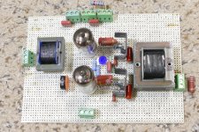
Here is a picture of a breadboard design. It is for a music synthesizer VCA, voltage controlled amplifier, where a DC control voltage can change the gain of the amp over a very wide range. It is a cascode design with a mosfet as the upper device. For this application a large dynamic range and gain control range is more important than absolute lowest distortion.
I did not try the 12AX7 in my prototype since it has too much gain for my application. I did try several dual triodes starting with the rare and expensive 6386 as used in the Fairchild 670 audio compressor. I also tried the 12AU7, 6BQ7, 6ES8, and many others. I eventually found that a 35 cent pentode tube that I have hundreds of, cascoded with a mosfet constant voltage source provided the best compromise for my application. I'm getting over 70 dB of gain control range while staying under 1% THD over 95% of the range.
Myself and others, notably forum user SY, have found that the venerable 12AX7 can be VERY linear when CCS loaded. Not all 12AX7's exhibit this characteristic though. None will live up to the mathematical excellence found in a spice model, but very low THD can be found in some tubes.
Combine a cascode circuit, a linear tube, and a CCS load and excellent performance can be found in a real world circuit.
Here is a picture of a breadboard design. It is for a music synthesizer VCA, voltage controlled amplifier, where a DC control voltage can change the gain of the amp over a very wide range. It is a cascode design with a mosfet as the upper device. For this application a large dynamic range and gain control range is more important than absolute lowest distortion.
I did not try the 12AX7 in my prototype since it has too much gain for my application. I did try several dual triodes starting with the rare and expensive 6386 as used in the Fairchild 670 audio compressor. I also tried the 12AU7, 6BQ7, 6ES8, and many others. I eventually found that a 35 cent pentode tube that I have hundreds of, cascoded with a mosfet constant voltage source provided the best compromise for my application. I'm getting over 70 dB of gain control range while staying under 1% THD over 95% of the range.
Attachments
Thanks Nick, but I don't believe that's what's at play here as I use the same balancing CCS with a regular LTP and I don't see such a huge reduction in THD there?
Well the THD is a the total harmonics, if you're feeding the combined harmonics back into CCS as negative (I believe I've seen a Broskie design and discussion with the feedback into the CCS) then it would attempt to cancel the harmonics.
Real tubes will have varying Rp so each tube's V->I*Rp function will vary. Worth trying.
Member
Joined 2009
Paid Member
Well the THD is a the total harmonics, if you're feeding the combined harmonics back into CCS as negative (I believe I've seen a Broskie design and discussion with the feedback into the CCS) then it would attempt to cancel the harmonics.
Real tubes will have varying Rp so each tube's V->I*Rp function will vary. Worth trying.
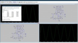
Yes, but why would the effect be almost 10x more effective with the cascode then without it? I find that rather puzzling. Obviously, as George's mentioned, the bulk of the 2nd harmonics cancel in the OPT, which is a benefit of a PP amplifier, but I'm at a loss why just adding the cascode yields an almost 10x reduction in THD? FYI please have a look at the attached schematics and THD results, this is for ~15W into 8 Ohm at 1kHz, THD is Vout across the load.
Attachments
Can you post the .asc files? Are these distortion figures (of the LTP) with global nfb in place? Possibly that is skewing the results as it seems as though there is a high overall gain and lots of feedback (more than is possible with real output transformers).
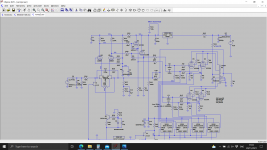
My last post, and the attached picture, shows exactly what I’m simulating, which indeed is a whole amplifier with a global nfb loop.
I think Tikiroo is onto it, the global NFBK has more gain with the cascode in place. If the output stage is modeling as near linear (maybe just 2nd Harmonic distortion that cleans up in P-P), then the main distortion source may be the cascode, which the Global NFdbk is then cleaning up with plenty of gain.
If you model the same amp without the Global N Fdbk, you may find the cascode stage to be putting out more distortion than the non-cascode. (check at output tube grids) The non-cascode has local triode N Fdbks operating, while the cascode does not. (but has a lot more gain available for the global N Fdbk case)
If you model the same amp without the Global N Fdbk, you may find the cascode stage to be putting out more distortion than the non-cascode. (check at output tube grids) The non-cascode has local triode N Fdbks operating, while the cascode does not. (but has a lot more gain available for the global N Fdbk case)
Last edited:
You can take a look at the following:
improvements on 12AX7 12AT7 EL34 schematic?
100W + 100W amp to share
improvements on 12AX7 12AT7 EL34 schematic?
100W + 100W amp to share
I think Tikiroo is onto it, the global NFBK has more gain with the cascode in place. If the output stage is modeling as near linear (maybe just 2nd Harmonic distortion that cleans up in P-P), then the main distortion source may be the cascode, which the Global NFdbk is then cleaning up with plenty of gain.
If you model the same amp without the Global N Fdbk, you may find the cascode stage to be putting out more distortion than the non-cascode. (check at output tube grids) The non-cascode has local triode N Fdbks operating, while the cascode does not. (but has a lot more gain available for the global N Fdbk case)
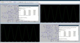
Yes, he's correct, just look at the open loop gain of the amplifier with and without the cascode in the below noted simulations, we gain almost 10dB at 1kHz, that's 20% more open loop gain. I'm liking the cascode!
Attachments
You can take a look at the following:
improvements on 12AX7 12AT7 EL34 schematic?
100W + 100W amp to share
Thanks, I've read through both topics, looks great!
Hedge made use of the cascode LTP,also see Glass audio article on a Dynaco ST70 upgrade. Morgan Jones used one in his Crystal Palace amp too, might be worth a look, see Valve Amplifiers.
Andy.
Andy.
Attachments
Hedge made use of the cascode LTP,also see Glass audio article on a Dynaco ST70 upgrade. Morgan Jones used one in his Crystal Palace amp too, might be worth a look, see Valve Amplifiers.
Andy.
Thanks, love the fact you uploaded the PDFs!

This is what I did for the last amp. The fets need close mathing.
Why did you use FETs in the input stage?
I wanted a modern sounding amp with 18dB of NFB and 30x gain for 120W output. The 12ax7/12ax7 did not offer enough gain in one stage so I moved over to a jfet which works out at about 300-400x voltage gain. By putting the grid of the top 12ax7 at 6-10V your well within the spec for the jfet. Either method you do need a trim pot in the tail to get the DC balance right. The jfets also need to be matched. Just another spin on the idea.
I wanted to avoid a first stage in this design. It's much more similar to SS amp in the VAS stage schematic wise.
I wanted to avoid a first stage in this design. It's much more similar to SS amp in the VAS stage schematic wise.
Last edited:
Okay, that makes sense, but in that case why not add a 2nd LTP stage? As I see you use a cathode follower (gain <1) after your input stage? Have a look at the screenshot in my previous post, I get about 43dB without and 52dB with the cascode at the input and that’s enough to allow a decent amount of global feedback.
- Home
- Amplifiers
- Tubes / Valves
- Cascoded 12AX7 LTP - Stupid good performance?